1
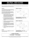
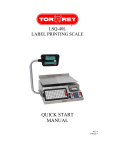
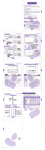
OutBack Power Systems HUB-4 and HUB-10 System Communication Manager Installation and User Guide Please check our website at www.outbackpower.com for the latest product information Installation & User Manual Page 1 HUB System Communications Manager Rev 1.1 10/10/03 Copyright 2003 OutBack Power Systems, Inc. 19009 62nd Ave NE, Arlington WA 98223 USA Tel 360 435 6030 Fax 360 435 6019 Installation & User Manual Page 2 HUB System Communications Manager Rev 1.1 10/10/03 Copyright 2003 OutBack Power Systems, Inc. 19009 62nd Ave NE, Arlington WA 98223 USA Tel 360 435 6030 Fax 360 435 6019 INTRODUCTION The OutBack Power Systems HUB-4 and HUB–10 System Communications Manager allows the interconnection of up to ten OutBack power conversion devices with the OutBack MATE. The interconnection creates a completely integrated Power System that is coordinated and managed by the MATE. The OutBack HUB communicates stacking phase, load share, incremental start-up and shut down information directly between the inverters. Interconnection cabling is standard CAT5 eight wire with RJ45 modular jacks. The HUB is powered via any FX inverter/charger or MX60. The OutBack HUB-4 allows the MATE to control any combination of four FX series inverters/chargers and MX60 charge controllers. The OutBack HUB-10 allows the MATE to control up to eight FX series inverters/chargers or up to 10 devices of any combination. Kit contents: HUB System Communications Manager Wiring Cover (2) #10 x ½” Philips head mounting screws (2) Snap-in 1” conduit bushings Installation & User Manual Page 3 HUB System Communications Manager Rev 1.1 10/10/03 Copyright 2003 OutBack Power Systems, Inc. 19009 62nd Ave NE, Arlington WA 98223 USA Tel 360 435 6030 Fax 360 435 6019 INSTALLATION The OutBack HUB is designed for surface mounting in an Indoor location. The cabling from the HUB to the FX inverters/chargers, MX60 PV MPPT charge controller and MATE uses standard CAT5 type computer cable. Consult your local inspector for specific installation requirements. The current and voltage in the communication cable is limited to less than 30 volts DC and considered to be a “limited energy circuit”. No conduit should be required. The HUB utilizes a snap on wiring cover to protect cabling, eliminate accidental unplugging of cables, and to provide a clean looking installation. This solid black cover unsnaps with a screw driver gently prying in the provided slots. Three phase stacking only The OutBack HUB is shipped from the factory setup for series (120/240 VAC split phase) and/or parallel (120 VAC or 230 VAC single phase) stacking. If three phase stacking is desired, the cover must be removed and a jumper position changed. The procedure for this is as follows: 1. Remove the black snap on wiring cover and all cables plugged into the HUB. Label the cable if you think you might confuse them. 2. Remove the four philips head screws from the bottom of the HUB. See Figure 1. Figure 1 3. Remove bottom cover and remove the four philips head screws holding the green PCB to the upper cover. See Figure 2. 4. Move the plug-in jumper from the series/parallel location to the three phase location. See Figures 3 & 4. 5. Figure 2 Replace PCB and bottom cover. Figure 3 Figure 4 Installation & User Manual Page 4 HUB System Communications Manager Rev 1.1 10/10/03 Copyright 2003 OutBack Power Systems, Inc. 19009 62nd Ave NE, Arlington WA 98223 USA Tel 360 435 6030 Fax 360 435 6019 MOUNTING The OutBack HUB can be wall mounted in any orientation, also the OutBack PS2AC has mounting holes for the HUB incorporated in to it. Typical Wall Mount PS2AC Mounting When mounting to an OutBack PS2AC, use the supplied #10 sheet metal screws to attach the HUB to the side of the PS2AC. Remove one or more of the two 1” knockouts, and insert the snap in conduit bushings supplied with the HUB. COMMUNICATION NETWORK CONFIGURATION TYPICAL HUB-10 CONFIGURATION TYPICAL HUB-4 CONFIGURATION Installation & User Manual Page 5 HUB System Communications Manager Rev 1.1 10/10/03 Copyright 2003 OutBack Power Systems, Inc. 19009 62nd Ave NE, Arlington WA 98223 USA Tel 360 435 6030 Fax 360 435 6019 WIRING ORDER Once mounted, cables can be connected to the HUB. The OutBack HUB has 4 to 10 RJ45 jacks (hence called Ports) that allow multiple OutBack products to be attached. These ports are numbered 1 to 10. The st port labeled 1 MATE is for the OutBack MATE to be plugged into. Due to the large number of possible HUB wiring combinations, it is suggested that OutBack devices to be connected be installed using one of the following methods. Connections can be made with the FX inverter/charger or MX60 MPPT charge controller powered up. For the FXs output breakers should be open until stacking programming is complete. The OutBack MATE should always be plugged in last. NOTE: To allow operation of the HUB, at least one OutBack power conversion device must be plugged into Port 1. Single FX or MX If only a single OutBack FX inverter/charger or a single MX60 MPPT charge controller is to be used, it should be plugged into Port 1 of the HUB. Additional OutBack inverters, controllers or other future OutBack devices such as the OutBack Smart Shunt can be plugged into any port. Multiple FXs non-stacked Multiple FX inverters/chargers can be plugged into any port as long as at least one FX is plugged into Port 1. Other OutBack devices can be plugged into any of the unused ports. Multiple MX60 controllers Multiple MX60 MPPT charge controllers can be plugged into any port as long as at least one is plugged into Port 1. Other OutBack devices can be plugged into any unused ports. Single/parallel phase stacked When connecting a “series-parallel stacked” inverter/charger system to a HUB, the FX inverter/charger that is to be the master must be plugged into Port 1. For clarity, any additional FXs should occupy the adjacent Ports. Other OutBack devices can be plugged into any of the unused ports. Some PC monitoring software requires that 120/240 VAC series stacked or series-parallel stacked FX inverter/charger systems be wired with all LEG 1 (L1) phased FXs as odd numbered Ports and all LEG 2 (L2) phased FXs as even numbered Ports. This arrangement also makes programming of the power save level settings of the slave FXs more intuitive. Three phase FX stacking When connecting a three phase stacked system the FX inverter/charger that is to be the master (Phase A) must be plugged into Port 1. The phase B slave must be connected to Port 2, and the phase C slave must be connected to Port 3. The HUB jumper must be in the three phase position as described in the Three phase stacking section. Other OutBack devices can be plugged into any unused ports. Currently, only three inverters can be configured in a three phase arrangement – but additional non-stacked inverters can be plugged into any of the unused ports of the HUB. Connecting the MATE THE OUTBACK MATE SHOULD BE CONNECTED LAST. It also must be connected to the jack labeled “1st MATE”. If any of the OutBack devices plugged into the HUB are powered, the MATE will power up as soon as it is connected. Upon powering up, the MATE will display a greeting and the software revision information. Immediately following this revision screen the MATE will display “Searching for Devices - HUB Found”. If the MATE does not find the HUB, check all wiring, make sure power is applied to all connected devices and try again. (See Troubleshooting Section) After the device found screen, the MATE will display a Port Assignment screen. Verify the device wiring with the Port Assignment screen. Installation & User Manual Page 6 HUB System Communications Manager Rev 1.1 10/10/03 Copyright 2003 OutBack Power Systems, Inc. 19009 62nd Ave NE, Arlington WA 98223 USA Tel 360 435 6030 Fax 360 435 6019 Pretty lights When the first OutBack product that is powered plugs into the HUB, the HUB will go through a power up sequence that flashes all of its LEDs. The POWER LED will remain on any time that one or more OutBack products that are powered are plugged in. After the MATE is plugged in, it will start communicating with all of the connected devices. Each Port has an LED associated with it that is visible through the cover. Any device that is plugged in should have a flickering LED when the MATE is communicating with it. Wiring Cover Knockouts The OutBack HUB has a wiring cover that has knockouts relieved into the plastic. Using a sharp knife, simply cut out the desired knockout for the MATE cable to pass through. Reinstall the wiring cover by snapping it over the posts on the side of the HUB. CONGRADULATIONS! Your OutBack Power Systems HUB is now installed. HUB OPERATION The OutBack HUB is designed to interconnect multiply OutBack Power Systems products to an OutBack MATE. This section will describe the operation of the MATE as it applies to the HUB, please see the MATE User Manual for more information. In order to operate correctly, the HUB requires that the MATE be code version 2.0 or higher. (See ‘Checking the MATE Version’ in the Troubleshooting section) Using the OutBack MATE with a HUB When the MATE is plugged into the HUB, immediately after the MATE displays the greeting screens, ‘Searching For Devices’ should be displayed, along with ‘Hub Found’. Searching For Devices HUB Found Port Assignment 1> FX 2> FX 3> MX 4> MX 5> 6> 7> 8> 9> 10> SM> Next the Port Assignment screen will be displayed, along with the ID of any connected OutBack Devices. In the example to the right, two FXs and two MXs are connected to the HUB. STATUS/FX/METER - P01 Output 120 vac Voltage DOWN UP TOP PORT While navigating the various screens and menus in the MATE, the information displayed often only applies to a single device on a single Port. In these cases the Port number is displayed in the upper left hand corner of the MATE screen. To navigate through the Ports, use the ‘PORT’ button, usually the left most lower button. Refer to the Troubleshooting section if any problems are encountered. Installation & User Manual Page 7 HUB System Communications Manager Rev 1.1 10/10/03 Copyright 2003 OutBack Power Systems, Inc. 19009 62nd Ave NE, Arlington WA 98223 USA Tel 360 435 6030 Fax 360 435 6019 Adding a Device to an operating HUB Any time an OutBack device is removed or added to a HUB, or its’ Port is changed, the MATE must re-poll the system to find the locations of all the new or moved devices. This is accomplished by either unplugging and replugging the MATE from the HUB, or by the following procedure: Make sure the MATE display is on its’ Main screen. Press and hold both lower left buttons simultaneously to return to the Main page from anywhere in the menus. Press the SETUP button then MATE to go to the SETUP/MATE screen MAIN---------------------------12:00:00P SUM STATUS SETUP ADV SETUP/MATE/PAGE1-------Choose category: CLOCK CNT GLOW PG2 Press PG2 and then COMM to go to the SETUP/MATE/COMM screen. SETUP/MATE/PAGE2-------Choose category: PG1 SUMRY COMM MAIN Press REPOLL to have the MATE find any new or moved OutBack products. Installation & User Manual Page 8 HUB System Communications Manager Rev 1.1 10/10/03 SETUP/MATE/COMM-------Choose category: BACK REPOLL PC DEBUG Copyright 2003 OutBack Power Systems, Inc. 19009 62nd Ave NE, Arlington WA 98223 USA Tel 360 435 6030 Fax 360 435 6019 TROUBLESHOOTING Hub power LED does not light The HUB is powered from other OutBack power conversion devices (FX or MX). Make sure that the DC breakers for all OutBack products connected to the HUB are on. Check or replace CAT5 cables running from the HUB to the OutBack products. MATE does not find the hub Check the revision screen on power up of the MATE. Code version must be 2.0 or higher. Check or replace CAT5 cables running from the HUB to the OutBack products, as well as the cable from the MATE to the HUB. MATE does not see all connected devices Verify that all connected devices have DC power applied and are functioning properly. Check or replace CAT5 cables running from the HUB to the OutBack products. If any OutBack products were added or moved on the HUB follow the instructions in ‘Adding a Device to an Operating HUB’ section. MATE displays a ‘COMM ERROR’ If the MATE receives too many interrupted or corrupt communications with OutBack products attached to the HUB, it will display a ‘COMM ERROR’ screen. Choosing ‘VIEW DEBUG’ takes you to a screen that lists all ports and accumulated 00:000 01:000 02:000 errors. Any Port 03:000 04:025 05:001 experiencing errors 06:001 07:001 08:001 can be found by the 09:001 10:001 2M:001 error count after the Port number. In the example to the right, Port 4 has a large number of errors detected (04:025 means Port 4: showing 25 errors). Pressing any key will take you to the SETUP/MATE/COMM screen, which will allow the error counts to be reset using the ‘RSET’ button, the Debug screen can be redisplayed by using the ‘VIEW’ button, or user can get back to the SETUP menu by using the ‘BACK’ button. Use the information on the Debug screen to locate the problem device. Make sure that its’ DC breaker in on, and that is operating correctly. Check or replace CAT5 cables running from the HUB to that device. Installation & User Manual Page 9 HUB System Communications Manager Rev 1.1 10/10/03 Copyright 2003 OutBack Power Systems, Inc. 19009 62nd Ave NE, Arlington WA 98223 USA Tel 360 435 6030 Fax 360 435 6019 ACCESSORIES MATE / HUB CABLES OBC-3 Three foot cable with green jacket OBC-6 Six foot cable with green jacket OBC-50 Fifty foot cable with green jacket Installation & User Manual Page 10 HUB System Communications Manager Rev 1.1 10/10/03 Copyright 2003 OutBack Power Systems, Inc. 19009 62nd Ave NE, Arlington WA 98223 USA Tel 360 435 6030 Fax 360 435 6019 OutBack Power Systems Two Year Limited Warranty OutBack Power Systems Inc. warrants that the products it manufacturers will be free from defects in materials and workmanship for a period of two (2) years subject to the conditions set forth below. The limited warranty is extended to the original user and is transferable. The limited warranty term begins on the date of invoice to the original user of the product. The limited warranty does not apply to any product or part thereof damaged by a) alteration or disassembly, b) accident or abuse, c) corrosion, d) lightning, e) reverse polarity, f) repair or service provided by an unauthorized repair facility, g) operation or installation contrary to instructions pertaining to the product. OutBack Power Systems’ liability for any defective product or any part thereof shall be limited to the repair or replacement of the product, at OutBack Power Systems’ discretion. OutBack Power Systems does not warrant or guarantee the workmanship performed by any person or firm installing its products. THIS LIMITED WARRANTY GIVES YOU SPECIFIC LEGAL RIGHTS, AND YOU MAY ALSO HAVE OTHER RIGHTS THAT VARY FROM STATE TO STATE (OR JURISDICTION TO JURISDICTION). OUTBACK POWER SYSTEMS’ RESPONSIBILITY FOR MALFUNCTIONS AND DEFECTS IN HARDWARE IS LIMITED TO REPAIR AND REPLACEMENT AS SET FORTH IN THIS LIMITED WARRANTY STATEMENT. ALL EXPRESS AND IMPLIED WARRANTIES FOR THE PRODUCT, INCLUDING BUT NOT LIMITED TO ANY IMPLIED WARRANTIES OF AND CONDITIONS OF MERCHANTABILITY AND FITNESS FOR A PARTICULAR PURPOSE, ARE LIMITED IN DURATION TO THE LIMITED WARRANTY PERIOD SET FORTH ABOVE AND NO WARRANTIES, WHETHER EXPRESS OR IMPLIED, WILL APPLY AFTER SUCH PERIOD. SOME STATES (OR JURISDICTIONS) DO NOT ALLOW LIMITATIONS ON HOW LONG AN IMPLIED WARRANTY LASTS, SO THE ABOVE LIMITATION MAY NOT APPLY TO YOU. OUTBACK POWER SYSTEMS DOES NOT ACCEPT LIABILITY BEYOND THE REMEDIES SET FORTH IN THIS LIMITED WARRANTY STATEMENT OR LIABILITY FOR INCIDENTAL OR CONSEQUENTIAL DAMAGES, INCLUDING WITHOUT LIMITATION ANY LIABILITY FOR PRODUCTS NOT BEING AVAILABLE FOR USE. SOME STATES (OR JURISDICTIONS) DO NOT ALLOW THE EXCLUSION OR LIMITATION OF INCIDENTAL OR CONSEQUENTIAL DAMAGES, SO THE ABOVE EXCLUSION OR LIMITATION MAY NOT APPLY TO YOU. During the two year period beginning on the invoice date, OutBack Power Systems will repair or replace products covered under this limited warranty that are returned to OutBack Power Systems’ facility or to an OutBack Power Systems authorized repair facility, or that are repaired on site by an OutBack Power Systems authorized repair technician. To request limited warranty service, you must contact OutBack Power Systems at 360-435-6030 within the limited warranty period. If limited warranty service is required, OutBack Power Systems will issue a Return Material Authorization (RMA) Number. Mark the outside of the package with the RMA number and include a copy of the purchase invoice in the package. You must ship the products back to OutBack Power Systems in their original or equivalent packaging, prepay shipping charges, and insure the shipment or accept the risk of loss or damage during shipment. OutBack Power Systems will ship the repaired or replacement products to you freight prepaid if you use an address in the continental United States, where applicable. Shipments to other locations will be made freight collect. Installation & User Manual Page 11 HUB System Communications Manager Rev 1.1 10/10/03 Copyright 2003 OutBack Power Systems, Inc. 19009 62nd Ave NE, Arlington WA 98223 USA Tel 360 435 6030 Fax 360 435 6019 REGISTER YOUR PRODUCTS Your purchase of an OutBack Power Systems product is an important investment. Registering your products will help us maintain the standard of excellence you expect from us in terms of performance, quality and reliability. Please take a moment to register and provide us with some important information. Name: _____________________________________________________________________________________________ Address: ____________________________________________________________________________________________ City, State, Zip Code: _____________________________________________________________________________________ Country: _____________________________________________________________________________________________ Telephone Number: ____________________________________________________________________________________ E-mail: _____________________________________________________________________________________________ Sold by: _____________________________________________________________________________________________ Installer: _____________________________________________________________________________________________ Purchase Date: _______________________________________________________________________________________ Model Number: _______________________________________________________________________________________ Serial Number: ________________________________________________________________________________________ Circle all that apply: Off-Grid Installation Grid-Tie Installation Residential Installation Commercial Installation _____________________________________________________________________________________________ EXTENDED WARRANTY APPLICATION OutBack Power Systems offers an optional three year extension to the standard two year limited warranty. Purchase of extended warranty coverage is available on products listed below provided conditions shown are met. Extended warranty coverage must be purchased within 90 days of the original sale of the product covered. PRODUCT REQUIRED SURGE PROTECTION EXTENDED WARRANTY COST FX2024 FX2048 MX60 MATE HUB 4 HUB 10 AC Input; AC Output, DC Input AC Input; AC Output, DC Input DC Input; DC Output NA NA NA $300.00 $300.00 $100.00 $50.00 $35.00 $50.00 Product Covered Serial Number Extended Warranty Cost Quantity Total Send check or money order payable to OutBack Power Systems. Include a completed copy of this application and send to: OutBack Power Systems Extended Warranty Program 19009 62nd Ave NE Arlington WA 98223 USA Installation & User Manual Page 12 HUB System Communications Manager Rev 1.1 10/10/03 Copyright 2003 OutBack Power Systems, Inc. 19009 62nd Ave NE, Arlington WA 98223 USA Tel 360 435 6030 Fax 360 435 6019