1
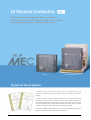
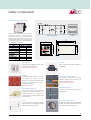
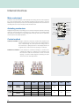
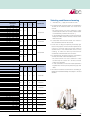
Leader in Electrics & Automation
Tri-MEC
LS Medium Voltage
Vacuum Contactors
Electric Equipment
Customer satisfaction through quality and serviceLS medium voltage vacuum contactors
LS medium voltage vacuum contactors using LS vacuum interrupters manufactured
with worldclass technology are type tested in LS PT & T that is accredited high power
test lab by worldclass KOLAS.
Contents
Features
4
Electrical circuit diagram
20
Technical data
10
Internal connection diagrams
22
Ordering information
12
External dimensions
24
External view
14
Selection tables
28
Safety components
15
Power fuse
30
Internal structure
16
Power fuse selection guides
31
Vacuum interrupters
17
Coordination graph
32
Accessories
18
Operation curves
34
Drawing operations
19
LS Vacuum Contactors
We have the major technology that others can not catch up.
LS vacuum contactors provide high withstand-current strength and
switching capacity as well as versatile auxiliary functions.
Fixed type
Drawout type (Standard type)
General description
LS Tri-MEC vacuum contactors are mainly used for the switching of motors,
transformers, capacitors in AC power lines. They can be installed in multi-stack
cubicles.
A vacuum contactor comprises several assemblies such as switching mechanism
including vacuum interrupters, magnetic actuator, high strength molded front
cover and auxiliary devices. Stable and high operating cycle is executed by the
vacuum interrupters made of high alumina ceramic tube which makes it possible
to degas in a high temperature with excellent mechanical strength.
Actuating is available either at instantaneous or continuous excitation. Functions for
safety in connecting and disconnecting are also provided.
4
E-Class Cradle
Direct-drawout type - for MCSG
F2-Class Cradle
Fuse connectable type (Standard type)
G-Class Cradle
Fuse connectable type (Direct-drawout type)
Operation conditions
Ambient temperature : -5 to 40℃
Maximum temperature of 24-hour mean : 35 ℃
Altitude : 1000m
Humidity : 24-hour measured average - max. 95% RH
1 month measured average - max. 90% RH
Applied standards
IEC Pub. 60470, IEC 60282-1, JEM 1167, KEMC 1126
5
Up-graded performance
Rated short-time current 6.3kA
[ 6.3kA ]
Performance is up-graded to rated short-time current 6.3kA/1sec.
and switching capacity 4kA according to IEC60470.
Short-circuit protection
[ 40kA ]
Power fused type vacuum contactors, in-house tested according to IEC 60282-1,
can provide short-circuit protection up to 40kA.
High performance, high reliability
and long service life
High speed interruption and short
arcing time
Reliable interruption of fault current
LS vacuum interrupters that comply with
IEC, ANSI and NEMA standards are
manufactured by the process of brazing
and degasing together in a high
vacuum furnace to assure high reliability.
It has fast recovering characteristic of
vacuum insulation. When opening it
breaks the current at the first current-zero
point to minimize the wearing of
contacts.
the devices and systems from fault current
LS current limiting power fuse can protect
by interrupting within half cycle.
High current such as short-circuit current
cause a fuse blown out due to the
reaction on the material inside of a fuse
Superior mechanical strength and
degasing
within such a short time.
Providing long service life and suited for
frequently operating purpose due to
using high alumina ceramic tube and
degasing in a high temperature.
Applied standards
6
IEC 282-1, DIN 43625, BS 2692, KSC 4612
Personnel safety
[ Safety ]
LS Tri-MEC vacuum contactors provide several auxiliary functions
for safe and comfortable use.
■Interlock button
■Drawout cradle for MCSG
■One-molded fuse holder
■Fuse checher and micro switch
Additional
equipment
■Unification bushing
■Mechanical interlock type
Suitable for Metal Clad
Switchgear
Interlock
The structure of G type cradle unification
equipped as standard.
For the safety of a operator interlock is
bushings and single-molded fuse-holder
barrier enables vacuum contactors to
Auxiliary contacts
build Metal Clad Switchgears.
Available up to 5NO+5NC.
Directly withdrawable equipment
This enables the withdrawing of a
vacuum contactor from a panel without
opening a door to prevent any possibility
Contactor over contactor arrangement
of electric shock.
7
Technical data
Fixed (Z) type
Type
Rated operation voltage
Rated voltage
LVC-3Z
-44�D
LVC-6Z
-44�D
LVC-3D
-42�D
LVC-6D
-42�D
LVC-3D
-44�D
[kV]
3.3
6.6
3.3
6.6
3.3
6.6
3.3
Ur[kV]
3.6
7.2
3.6
7.2
3.6
7.2
3.6
le[A]
Rated frequency
fr[Hz]
200
400
200
3.3
7.2
3.6
7.2
400
E : Continuous 1200, L : Instantaneous 300
×10,000operations]
[×
E : Continuous 300, L : Instantaneous 50
30
Impulse withstand
Up[kVp]
60
Dielectric strength
Ud[kV/1min]
20
Excitation method
E : Continuous, L : Instantaneous
Control voltage
[V]
Arrangement
AC 110V, AC 220V, DC 110V
Continuous 3a3b, Instantaneous 2a2b
Current
[A]
Voltage
[V]
Motors
[kW]
750
Transformers
[kVA]
1,000
2,000
Capacitors
[kVA]
750
1,500
Weight
[kg]
2a2b
2a2b
10 (AC)
600max ~ 48min
1,500
1,500
3,000
750
2,000
4,000
1,200
2,000
24
Note) 고정형 상시조작형은 6a6b 가능
Power fuse
Power fuses can be installed into combination(G, GB) type contactors
for the protection of equipments and systems from short-circuit.
Fuse ratings are selected properly after system analysis and some
accessories such as fuse link clips should be selected by the fuse rating.
8
3.6
60
[op./hr]
×10,000operations]
[×
Max. Applicable
7.2
6.6
4
Mechanical
Auxiliary contact
3.3
200
Electrical
Lifetime
6.6
2.4kA-30s, 4kA-10s, 6kA-2s, 6.3kA-1s, 8kA-0.5s, 10kA-0.1s
(kApeak- 0.5Cycle)
Switching frequency(AC3)
6.6
50/60
(kA-sec)
Rated short-time peak current
LVC-6D LVC-3DB LVC-6DB LVC-3DB LVC-6DB
-44�D -42�D -42�D -44�D -44�D
400
(kA, O-3min-CO-2min-CO)
Rated short-time current
Direct-drawout (DB) type - for MCSG
LVC-6Z
-42�D
Rated operational current
Rated breaking current
Drawout (D) type
LVC-3Z
-42�D
1,500
1,500
1,000
2,000
750
1,500
41
3,000
750
1,500
1,500
2,000
4,000
1,000
2,000
2,000
4,000
1,200
2,000
750
1,500
1,200
2,000
56
3,000
Combination drawout (G) type
Type
LVC-6G
-42�D
LVC-3G
-44�D
LVC-6G
-44�D
LVC-3GB
-42�D
LVC-6GB
-42�D
LVC-3GB
-44�D
LVC-6GB
-44�D
[kV]
3.3
6.6
3.3
6.6
3.3
6.6
3.3
6.6
Ur[kV]
3.6
7.2
3.6
7.2
3.6
7.2
3.6
Rated operation voltage
Rated voltage
Rated operational current
le[A]
Rated frequency
Combination direct-drawout (GB) type - for MCSG
LVC-3G
-42�D
200
400
200
fr[Hz]
Rated breaking current
PF Combination
Rated breaking
current
50/60
(kA, O-3min-CO-2min-CO)
4 kA (40kA with fuse)
Making
40kA
Breaking
40kA
take over(O-3min-O-3min-O)
Rated short-time current
4kA
(kA-sec)
Rated short-time peak current
2.4kA-30s, 4kA-10s, 6kA-2s, 6.3kA-1s, 8kA-0.5s, 10kA-0.1s
(kApeak- 0.5Cycle)
Switching frequency(AC3)
60
[op./hr]
E : Continuous 1200, L : Instantaneous 300
Mechanical
×10,000operations]
[×
E : Continuous 300, L : Instantaneous 50
Electrical
×10,000operations]
[×
30
Impulse withstand
Up[kVp]
60
Dielectric strength
Ud[kV/1min]
Lifetime
7.2
400
20
Excitation method
E : Continuous, L : Instantaneous
Control voltage
Auxiliary contact
[V]
AC 110V, AC 220V, DC 110V
[A]
10 (AC)
Arrangement
2a2b
Current
Voltage
[V]
Weight
600max ~ 48min
[kg]
46
62
Note) 적용부하용량은 파워퓨즈의 정격에 따라 상이합니다.
Power fuse ratings combination type
Standard
Rated
voltage(kV)
Rated current(A)
LFL-3/6G-�B
3.6/7.2
5, 10, 20, 30, 40, 50, 63, 75, 100
LFL-3/6G-�B
3.6/7.2
Type
DIN type
LFL-3G-�B
3.6
160, 200
LFL-6G-�B
7.2
160, 200
LFL-3/6G-�
3.6/7.2
General
use
125 Note1)
LFL-3G-�
3.6
LFL-6G-�
7.2
LFL-3M-�
3.6
192
45
292
292
292
Application
All application
including transformers,
motors and capacitors
50
75(T50), 100(T75)
60
311
General use
150(T100), 200(T150)
60
311
transformers
300(T250), 400(T300)
77
311
capacitors.
150(T100), 200(T150)
77
311
261
M20, M50, M100
60
200
M150, M200
77
200
M300(M400) Note2)
87
250
Motors
M20, M50
60
311
capacitors.
M100, M150 ,M200
77
350
87
450
For
motors
7.2
(mm)
5(T1.5), 10(T3), 20(T7.5), 30(T15), 40(T20), 50(T30), 60(T30)
KS type
LFL-6M-�
Diameter
(mm)
M300(M400) Note2)
Note1) 퓨즈 정격전류가 100A를 초과시 퓨즈체커를 이용한 VC 연동을 금지합니다.
Note2) M400적용시 자사와 협의 바랍니다.
� LFL-6G-300, 400은 VC에 조합이 불가합니다.
9
Ordering information
Contactor
Control voltage(kV)
Fuse checker
PT
Position Switch
FUSE type
D1
DC 110
0
Without
0
Without PT
0
Without
01
LFL-3/6G-5~60
L261-∅50
A1
AC 110
1
With
1
1EA of 100Var
1
With
02
LFL-3M-20~100
L200-∅60
LFL-3/6G-75~100
L311-∅60
A2
AC 220
2
2EA of 100Var
3
1EA of 200Var
4
2EA of 200Var
03
LFL-3G-150~200
04
LFL-3M-150~200
L200-∅77
LFL-3G-300~400
L311-∅77
LFL-6M-20~50
05
Contactor type
LS Vacuum
Contactor
10
Rated voltage(kV)
Installation
3
3.6
Z
Fixed type
6
7.2
D
Drawout type
G
Combination drawout type
(Fuse connectable)
DB
Direct-drawout type
(For MCSG)
GB
Combination directdrawout type
(Fuse connectable
and for MCSG)
Breaking current(kA)
4
4
Rated current(A)
2
200
4
400
LFL-6G-150~200
06
LFL-6M-100~200
L350-∅77
07
LFL-3M-300
L250-∅87
08
LFL-6M-300
L450-∅87
09
LFL-3/6G-5B~100B
L258-∅45
10
LFL-3/6G-125B~200B L358-∅45
Control method
E
L
Continuous
excitation
Instantaneous
excitation
Modification No.
D
Tri-MEC
Conventional
C
type
Cradle
LS Cradle
Rated voltage(kV)
3/6
3.6/ 7.2kV
common
Ratings
Cradle Type
Breaking current
42
/
44
E
Position Switch
E class
PS1
1a1b
PS2
2a2b
4kA
F
F2 class (with shutter only)
Rated current
G
G class (with shutter and bushings)
200/400A common
B
For MCSG
Mechanical interlock type
LS Vacuum
Contactor
Mechanical
Interlock
Vacuum Contactor
(VC1)
Control voltage(V)
DC 110V
Vacuum Contactor
(VC2)
Control voltage(V)
D1
D1
DC 110V
32E
LVC-3Z-42ED
A1
AC 110V
32E
LVC-3Z-42ED
A1
AC 110V
34E
LVC-3Z-44ED
A2
AC 220V
34E
LVC-3Z-44ED
A2
AC 220V
62E
LVC-6Z-42ED
62E
LVC-6Z-42ED
64E
LVC-6Z-44ED
64E
LVC-6Z-44ED
32L
LVC-3Z-42LD
32L
LVC-3Z-42LD
34L
LVC-3Z-44LD
34L
LVC-3Z-44LD
62L
LVC-6Z-42LD
62L
LVC-6Z-42LD
64L
LVC-6Z-44LD
64L
LVC-6Z-44LD
11
External view
�
�
�
�
�
�
�
�
�
�
�
�
� Front cover
� Fuse checking window
�
� Connector
�
� Unlock button(Interlock lever)
� Handle(Draw-in and Drawout)
�
� ON/OFF indicator
� Operation counter
�
� Manual trip button
� Drawout carrier
�
� Direct drawout carrier
�
� Interlock lever
�
� Interlock button
� Hole for Interlock lever insertion
�
� Test/Run indicator
�
�
� Cradle
� CTD(Condensor trip device)
� �
12
�
� Fuse case
Safety components
CTD(Condensor Trip Device)
(For discharge)
AC input
CTD is built as standard in the contactor
with AC control of instantaneous
excitation so that the contactor can be
tripped within 30 seconds in the event of
an electricity failure. The automatic trip
circuit in the event of an electricity failure
is to be built by a customer.
DC output
Control circuit diagram
Terminal
Rating
Description
Type
CTD-100
CTD-200
AC 100/110 AC 200/220
Rated input voltage(V)
Frequency(Hz)
50/60
50/60
Rated impulse voltage(V)
140/155
280/310
Charging time
Within 5 sec.
Within 5 sec.
Trip command
possible time
Max. 30 sec.
Max. 30 sec.
Input voltage range
μF)
Capacitor rating(μ
85%~110%
400
85%~110%
160
Dimensions
Fuse case
Counter
Made of high strength BMC resin to offer
This is a ON/OFF operation counter by
superior insulation and safety.
using 5 digit.
Note) Applied fuse combination type.
Bushing
It is mono-block bushing to be used in
the cradles of G-type drawout
contactors. It provides high insulation
level, so recommended to use in
contactors for MCSG.
Test/Run position indicator
This enables checking contactor
positions visibly when connecting or
disconnecting a contactor.
Note) Applied direct drawout type only.
Note) Applied G-Class Cradle.
Direct-drawout carrier
ON/OFF indicator
It is a screw-sliding type drawout
To visiblly check whether power is
equipment to draw-in and draw-out a
supplied or not
contactor directly out of a panel for
personal safety. It is built in DB and GB
type contactors.
Lever
Fuse checking window
It is a bent-lever to actuate a direct-
Enables the visible check of a fuse like its
drawout carrier by inserting and turning
outside status and temperature-rise in a
in DB and GB type contactors
fuse combination type contactor.
13
Internal structure
Main contact part
Consists of vacuum interrupters, main terminals and moving shunts that are supported
by a one-moulded frame that maintains insulation between phases. Vacuum
interrupters are operated by means of the actuating mechanism that is connected to
movable parts of a vacuum interrupter with a insulation rod.
Protection cover
Line terminal
Insulation
mold frame
Actuating mechanism
Vacuum
interrupter
Load terminal
Insulation rod
Designed simply without any linkage to be suited for frequent-operation and long
service life. The actuating lever connected to a moving core of a actuating magnet
Shunt
Contact spring
Actuating lever
Control coil
Fixed core
that carrys out the function of a actuating shaft moves up and down to control the
Moving core
Return spring
contact pressure for stable operations.
Spring guide Spring spacer
Control method
Main contact part
Continuous excitation - During a contactor is closed the control coil is required to be
excited continuously to pull the moving core magnetically. In
case of discontinuing the control power the moving core is to
be returned by a spring because of the disappearance of
magnetic force, which causes the opening of a contactor.
Instantaneous excitation - In this method the continuous exciting of a control coil to
maintain the closing of a contactor is not required as the
latch built in it holds the mechanism. In case of manual
tripping, a contactor will be tripped by releasing the latch
Latch mechanism
when turn on the manual trip button.
Continuous excitation
Instantaneous excitation
Control voltage Closing current(A)/
Trip current(A)/
Holding current(A)/
Pick-up
Drop-out
Tripping
(V)
time(ms)
time(ms)
time(ms)
voltage
voltage
voltage
DC 110
3/100
-
0.6/40
AC 110
3/100
-
0.6/40
85%
75%
-
2/100
-
0.3/40
4.5/145
3/35
-
4.5(6)/145
3(4)/35
-
85%
75%
10%~75%
3(4)/145
10(14)/35
-
Type
Control method
�LVC-3/6�
Continuous
excitation(E)
AC 220
Instantaneous excitation(L)
DC 110
Instantaneous excitation(L)
(With CTD)
AC 110
AC 220
42/44ED
�LVC-3/6�
42/44LD
Note) The values in ( ) are maximum allowable currents in case of using CTD. (voltage increment considered)
14
Vacuum interrupters
Features
Vacuum interrupters
In the closed position, normal current flows
Moving electrode
through the interrupter. When a fault occur
Moving electrode terminal
and interruption is required, the contacts are
quickly separated. The are which is oriented
Bellows
between surfaces of contact shall diffuse at
Bellows shield
the contact structure of flat shape. It prevents
Ceramic
local heating and damage. The arc burns in
Arc shield
an ionized metal vapor, which condenses on
the surrounding metal shield.
Contact
Fixed electrode terminal
The arc is extinguished and vapor production
Fixed electrode
is ceased at current zero. The metal vapor
External view
Internal structure
plasma is very rapidly dispersed, cooled,
recombined, and deionized, and the metal
LS vacuum interrupters consists of spiral contact,
vapor products are quickly condensed so that
the material of which is CuCr to provide a long service life and
the contacts withstand the transient recovery
high withstand voltage characteristic.
voltage.
Ratings
Fixed electrode
Rated voltage
(kV)
7.2
Rated current
(A)
400
(kA)
4.5
Contact stroke
(mm)
4.75
Opening speed average
(m/s)
0.6
Closing speed average
(m/s)
0.3
Contact force
(kg)
7 Min
Moving side weight
(kg)
0.23
(kg)
0.52
(mm)
1
Rated interrupting current
Interrupter weight
Max. contact erosion
Dimensions
(i) Weld
(ii) Bridge explosion
Arc initiation
Fault
current
(i) Contact jets
(ii) Shield involvement
High current arc mode
(i) Arc instability
(ii) Interruption
Current zero
Time (㎲)
Time (ms)
Voltage phenomena
(i) Arc re-ignition
(ii)Restrikes
(iii) B.I.L
(iv) A.C.voltage withstand
Recovery voltage
AC arcing and interruption phenomena in vacuum
15
Accessories
Fuse checker / Micro switch
Fuse checker is operated in case of fuse blowing and output
mechanical signal at same time. A micro switch is a part of
fuse checker. The mechanical input signal is changed to
electrical out signal by micro switch.
Note) 19-20 : NO contact, 19-21 : NC contact
Fuse checker / Micro switch
PT(Potential transformer)
2 each of PTs can be mounted on drawout type contactors and fuse
combination type.
These are 100VA and 200VA PTs rated 3.6/7.2kV.
Rated voltage(V)
Secondary voltage(V)
Class
Burden(Var)
Frequency(Hz)
3300/6600
110/220
1
100/200
50/60
PT(Potential transformer)
Fuse clip
It is used to install or uninstall a fuse link to the holder.
Its dimensions depend on ratings.
Note) Refer to fuse selection table on page 11.
Fuse clip
Auxiliary switch
Auxiliary switches are 2NO+2NC as standard and additional 3NO+3NC can
be added on request.
Auxiliary switch
Position switch
This enables checking contactor positions when draw-in and draw-out.
Remote checking is also possible through signaling via micro switches in each
position.
16
Drawing operations
For standard draw-out types (D, G)
■ When draw-in a contactor into a cradle.
<TEST Position>
Cradle
1. Check that the contactor is in the state of open (TEST Position).
2. While pushing the unlock push button, insert the contactor about 50mm into the
cradle.
3. Release the unlock push button and push the contactor into the cradle by the
Unlock
button
Interlock
plate
RUN position.
Unlock pin
■ When draw-out a contactor from a cradle.
1. Check that the contactor is in the state of open (RUN Position).
2. While pushing the unlock push button, draw the contactor about 50mm out of
<RUN Position>
the cradle.
Cradle
3. Release the unlock push button and pull the contactor from the cradle by the
TEST position.
Unlock
button
Unlock
plate
Unlock
108mm(Stroke)
Unlock
Unlock pin
Details of TEST/RUN Position
For direct draw-out types (DB, GB)
<TEST Position>
Cradle
■ When draw-in a contactor into a cradle.
1. Check that the contactor is in the state of open (TEST Position).
2. While pushing the both sides of Interlock handle to the direction of the arrows,
insert the contactor about 50mm into the cradle.
3. Insert the drawout lever into a hole as shown in the fig. While pushing the
Interlock push button, swing the lever clockwise two times and release the
Interlock push button.
Interlock
lever
Interlock
button
A hole for a
drawout lever
4. Turning the lever clockwise until the contactor reaches in the RUN position.
■ When draw-out a contactor from a cradle.
<RUN Position>
Cradle
1. Check that the contactor is in the state of open (RUN Position).
2. Insert the drawout lever into a hole as shown in the fig. While pushing the
Interlock push button, swing the lever counterclockwise two times and release
Interlock
lever
the Interlock push button.
4. Turning the lever counterclockwise until the contactor reaches in the TEST
position.
Interlock
button
A hole for a
drawout lever
5. In case of separating the contactor from the cradle pull the contactor while
pushing the both sides of Interlock handle to the direction of the arrows as
shown in the fig.
Note) Check the power before connecting or disconnecting.
17
Electrical circuit diagram
Fixed type (Continuous excitation)
Continuous excitation
DC control
�Impress the power to terminal No.1 and 2.
�ON/OFF operating by using contacts of terminal No.3 and 4.
Note) ----- : User's wiring part
AC control
�Impress the power to terminal No.1 and 2.
�ON/OFF operating by using contacts of terminal No.3 and 4.
Note) ----- : User's wiring part
18
Fixed type (Instantaneous excitation)
Instantaneous excitation
DC control
�Impress the power to terminal No.1 and 2.
�Input : ON/OFF operating by using No.4 terminal
�Output : Trip by using No.5 terminal
Note) ----- : User's wiring part
AC control(CTD equipped)
�Impress the power to terminal No.1 and 2.
�Input : ON/OFF operating by using No.4 terminal
�Output : Trip by using No.5 terminal
Note) ----- : User's wiring part
19
Internal connection diagrams
Drawout type (Continuous excitation)
Continuous excitation
DC control
�Impress the power to terminal No.1 and 2.
�ON/OFF operating by using contacts of terminal No.3 and 4.
Note) ----- : User's wiring part
AC control
�Impress the power to terminal No.1 and 2.
�ON/OFF operating by using contacts of terminal No.3 and 4.
Note) ----- : User's wiring part
20
Drawout type (Instantaneous excitation)
Instantaneous excitation
DC control
�Impress the power to terminal No.1 and 2.
�Input : ON/OFF operating by using No.4 terminal
�Output : Trip by using No.5 terminal
Note) ----- : User's wiring part
AC control(CTD equipped)
�Impress the power to terminal No.1 and 2.
�Input : ON/OFF operating by using No.4 terminal
�Output : Trip by using No.5 terminal
Note) ----- : User's wiring part
21
Connection diagrams
Mechanical interlock type (Instantaneous excitation)
Instantaneous excitation
DC
VC1
A
13
A2
B
43
x
14
A
CC
AC
1 12
2 13
14
4
5
44
7
8
9
10
11
x Relay
TC
7
11
15
14
9
13
11
27
26
25
24
23
22
21
17
16
15
14
13
12
11
8
12
5
24
10
14
4
AUX S/W 1
<2a2b>
VC2
A
13
B
43
x
14
A
AC
A2
1 12
2 13
14
4
5
CC
44
7
8
9
10
11
x Relay
TC
7
11
15
14
9
13
11
<2a2b>
27
26
25
24
23
22
21
17
16
15
14
13
12
11
8
12
5
24
10
14
4
AUX S/W 2
AC (With CTD)
VC1
13
A
-
Z
+
44
CC
11
15
14
9
13
11
<2a2b>
14
15
C1
A
7
13
3
5
x Relay
TC
12
2
4
14
~
B
43
x
~
AC
A2
1
27
26
25
24
23
22
21
17
16
15
14
13
12
11
8
12
5
24
10
14
4
C3
C5 C6
4
5
6
7
1
2
3
8
9
7
8
9 10 11 12
CTD
10
11
AUX S/W 1
VC2
13
-
Z
~
B
CC
<2a2b>
A2
43
x
~
AC
22
A
+
14
44
17
16
15
14
13
12
11
13
3
14
15
5
x Relay
7
11
15
14
9
13
11
12
2
4
C1
A
TC
1
27
26
25
24
23
22
21
AUX S/W 2
8
12
5
24
10
14
4
C3
C5 C6
4
5
6
7
1
2
3
8
7
8
9 10 11 12
9
10
11
CTD
Mechanical interlock type (Continuous excitation)
Continuous excitation
DC
1
3
1 12
2 13
3 14
4 15
5 16
VC1
4
ON
OFF
(+)
Vzb1
R
Vzb2
DC
CC
CC
2
1
2
3
4
5
6
12
13
14
15
16
B
A
11
10 12
6
A
6
9
B
5
11
15
14
9
13
11
CC
13 15
14
10
11
A
A
CC
9
5
R22 R2
CC
B
(-)
R21
R12 R
B
CC
9
10
11
R11
16
27
17
16
15
14
13
12
11
26
25
24
23
22
21
6
12
16
24
10
14
AUX S/W 1
<3a2b>
1 12
2 13
3 14
4 15
5 16
VC2
1
3
4
R11
ON
OFF
(+)
Vzb2
R
Vzb1
DC
CC
CC
2
1
2
3
4
5
6
12
13
14
15
16
B
B
A
6
11 13
10 12
14
9
B
A
10
11
A
CC
9
5
6
CC
B
(-)
R22 R2
A
CC
9
10
11
R21
R12 R
5
11
15
14
9
13
11
CC
15
16
27
17
16
15
14
13
12
11
26
25
24
23
22
21
6
12
16
24
10
14
AUX S/W 2
<3a2b>
AC
1
VC1
4
3
ON
OFF
Vzb1
R
Vzb2
AC
1
2
3
4
5
6
12
13
14
15
16
B
A
CC
CC
2
B
11
9
6
10 12
12
13
14
15
16
CC
A
A
5
11
15
14
9
13
11
CC
13 15
~
+
14
R22 R
B
CC
5
R12 R
A
CC
9
10
11
R2
R1
B
1
2
3
4
5
6
Z
-
27 6
26 12
25 16
24 24
23 10
22 14
21
9
10
11
AUX S/W
~
16
17
16
15
14
13
12
11
<3a2b>
VC2
1
1
2
3
4
5
6
4
3
ON
OFF
Vzb2
R
Vzb1
AC
1
2
3
4
5
6
12
13
14
15
16
B
A
CC
B
CC
2
5
9
11
CC
9
10
11
R12 R
A
B
A
CC
A
5
11
15
14
9
13
11
CC
13 15
~
Z
~
10 12
R22 R
CC
+
6
R2
R1
B
12
13
14
15
16
-
17
16
15
14
13
12
11
27
26
25
24
23
22
21
6
12
16
24
10
14
9
10
11
AUX S/W
14 16
<3a2b>
23
External dimensions
Fixed type
〔Unit : mm〕
〕
LVC-3/6Z-42/44E(L)D
(Terminal hole)
Mounting hole
Drawout type w/o a cradle
LVC-3/6D-42/44E(L)D
Combination drawout type
w/o a cradle (Fused combination)
LVC-3/6G-42/44E(L)D
24
(Terminal hole)
Mounting hole
Drawout type
〔Unit : mm〕
〕
E-Class Cradle
(Terminal hole)
(Terminal hole)
Mounting hole
Mounting hole
F2-Class Cradle
(Terminal hole)
(Terminal hole)
Mounting hole
Mounting hole
G-Class Cradle
(Terminal hole)
(Terminal hole)
Mounting hole
Mounting hole
25
External dimensions
Combination drawout type
〔Unit : mm〕
〕
(Fused combination)
E-Class Cradle
(Terminal hole)
(Terminal hole)
Mounting hole
Mounting hole
F2-Class Cradle
(Terminal hole)
(Terminal hole)
Mounting hole
Mounting hole
G-Class Cradle
(Terminal hole)
(Terminal hole)
26
Mounting hole
Mounting hole
Direct-drawout type
〔Unit : mm〕
〕
(For MCSG)
B-Class Cradle
(Terminal hole)
(Terminal hole)
Mounting hole
Mounting hole
Mechanical Interlock type
27
17
26
16
25
24
15
14
23
13
22
12
21
11
27
17
ON
26
25
16
15
24
14
23
13
22
12
21
11
27
Selection tables
Fuse selection by load
Fuse link
Application
Rated
Lowest
Rated Rated
interrupting interrupting
voltage current current
current
DIN type
Model
LFL
LFL
LFL
LFL
LFL
LFL
LFL
LFL
LFL
LFL
LFL
LFL
LFL
LFL
LFL
LFL
LFL
LFL
LFL
LFL
LFL
LFL
LFL
LFL
LFL
LFL
(kV)
- 3/6G - 5B
- 3/6G - 10B
- 3/6G - 20B
- 3/6G - 30B
- 3/6G - 40B
- 3/6G - 50B
- 3/6G - 60B
- 3/6G - 75B
- 3/6G - 100B
- 3/6G - 125B
- 3G - 160B
- 3G - 200B
- 6G - 160B
- 6G - 200B
- 20G - 5B
- 20G - 10B
- 20G - 20B
- 20G - 30B
- 20G - 40B
- 20G - 50B
- 20G - 60B
- 20G - 75C
- 20G - 100C
- 20G - 125B
- 20G - 160B
- 20G - 200B
3.6
(7.2)
3.6
7.2
24
(kA)
(A)
5
10
20
30
40
50
63
75
100
125
160
200
160
200
5
10
20
30
40
50
60
75
100
125
160
200
(A)
4In
40
5In
25
Capacitive load(kVA)
Transformer load(kVA)
Single phase
4
6
15
21
40
49
66
68
128
151
211
265
~ 8
~ 13
~ 31
~ 42
~ 82
~ 102
~ 137
~ 165
~ 220
~ 275
~ 352
~ 440
20
43
99
149
267
345
430
580
923
1,364
2,125
2,650
※( 8 ~
( 13 ~
( 30 ~
( 40 ~
( 80 ~
( 98 ~
(132 ~
(134 ~
(256 ~
(302 ~
(
(
(425 ~
(437 ~
~ 43
~ 90
~ 206
~ 310
~ 557
~ 719
~ 897
~ 1,145
~ 1,527
~ 1,908
~ 2,443
~ 3,050
Three phase
6.7
11
25
35
69
85
114
117
222
261
365
495
16 )
25 )
62 )
84 )
165)
204)
275)
330)
440)
550)
)
)
704)
880)
~ 14
~ 22
~ 53
~ 73
~ 143
~ 117
~ 238
~ 285
~ 381
~ 476
~ 610
~ 762
36
75
172
258
464
598
745
1,000
1,600
2,362
3,680
4,593
※( 13 ~ 28 )
( 21 ~ 44 )
( 51 ~ 107 )
( 70 ~ 145 )
(137 ~ 286)
(170 ~ 354 )
(229 ~ 476 )
(233 ~ 571 )
(443 ~ 762 )
(522 ~ 952 )
(
)
(
)
(735~1,220 )
※ (755~1,520 )
~ 75
~ 157
~ 358
~ 538
~ 965
~ 1,246
~ 1,554
~ 1,983
~ 2,645
~ 3,304
~ 4,232
~ 5,287
Three phase
9.8up to ※( 9.8up to )
9.8 ~ 12
( 19 ~ 24 )
12 ~ 31
( 24 ~ 61 )
31 ~ 46
( 61 ~ 92 )
46 ~ 64
( 92 ~ 128)
64 ~ 81
(128 ~ 163 )
181 ~ 105
(163 ~ 210 )
105 ~ 150
(210 ~ 300 )
150 ~ 222
(300 ~ 445 )
222 ~ 275
(445 ~ 550 )
275 ~ 370
(
)
370 ~ 550
(
)
(550~742 )
(742~1,000 )
46up to
46 ~ 83
83 ~ 203
203 ~ 317
317 ~ 425
425 ~ 564
564 ~ 710
710 ~ 1,021
1,021 ~ 1,655
1,655 ~ 2,370
2,370 ~ 3,170
3,170 ~ 4,000
Fuse selection by load
Fuse link
Application
Rated
Lowest
Rated Rated
interrupting interrupting
voltage current current
current
KS type
Model
G(General use)
type
M(Motor protection) type
28
LFL
LFL
LFL
LFL
LFL
LFL
LFL
LFL
LFL
LFL
LFL
LFL
LFL
LFL
LFL
LFL
LFL
LFL
LFL
LFL
LFL
LFL
LFL
LFL
LFL
LFL
LFL
LFL
LFL
LFL
LFL
- 3/6G
- 3/6G
- 3/6G
- 3/6G
- 3/6G
- 3/6G
- 3/6G
- 3/6G
- 3/6G
- 3G
- 3G
- 3G
- 3G
- 6G
- 6G
- 6G
- 6G
- 3M
- 3M
- 3M
- 3M
- 3M
- 3M
- 3M
- 6M
- 6M
- 6M
- 6M
- 6M
- 6M
- 6M
(kV)
- 5
- 10
- 20
- 30
- 40
- 50
- 60
- 75
- 100
- 150
- 200
- 300
- 400
- 150
- 200
- 300
- 400
- 20
- 50
- 100
- 150
- 200
- 300
- 400
- 20
- 50
- 100
- 150
- 200
- 300
- 400
3.6
(7.2)
3.6
7.2
3.6
7.2
(A)
5
10
20
30
40
50
63
75
100
150
200
300
400
150
200
300
400
20
50
100
150
200
300
400
20
50
100
150
200
300
400
(kA)
40
40
(A)
5In
7In
Transformer load(kVA)
Single phase
※ ( 5up to )
10up to ( 15up to )
20up to ( 50up to )
30up to ( 75up to )
50up to ( 100up to )
75up to ( 150up to )
(
)
150up to ( 200up to )
200up to ( 400up to )
300up to (
)
400up to (
)
625up to (
)
750up to (
)
( 500up to )
( 750up to )
(1,250up to)
(
)
-
Capacitive load(kVA)
Three phase
Three phase
5up to ※( 15up to )
15up to ( 30up to )
30up to ( 75up to )
75up to ( 150up to )
100up to ( 200up to )
150up to ( 300up to )
(
)
200up to ( 400up to )
375up to ( 750up to )
500up to (
)
750up to (
)
1,000up to (
)
1,500up to (
)
(1,000up to)
(1,500up to)
(2,000up to)
(2,500up to)
※(
)
10up to ( 25up to )
30up to ( 50up to )
50up to ( 100up to )
75up to ( 150up to )
100up to ( 200up to )
(
)
200up to ( 400up to )
300up to ( 600up to )
400up to (
)
600up to (
)
1,000up to (
)
(
)
( 800up to )
(1,200up to)
(
)
(
)
50up to ※(
)
150up to (
)
300up to (
)
400up to (
)
800up to (
)
1,000up to (
)
(
)
( 100up to )
( 300up to )
( 600up to )
( 800up to )
(
)
(
)
(
)
Fuse selection by load
Selecting conditions and warning
Dimensions(mm)
Applicable holder
Motor load(kVA)
A
B
C
D
) apply to the loads of 7.2kV.
2. It is assumed that the inrush current of a transformer is
Three phase
6.5 ~10.7 ※( 13 ~ 22 )
10.7 ~ 28
( 22 ~ 36 )
28 ~ 57
( 36 ~ 86 )
50 ~ 85
( 86 ~ 117 )
85 ~ 115
(117 ~ 230)
115 ~ 142
(230 ~ 284 )
138 ~ 191
(276 ~ 382 )
181 ~ 252
(362 ~ 503 )
253 ~ 369
(469 ~ 739 )
293 ~ 435
(556 ~ 870 )
343 ~ 572
(
)
375 ~ 630
(
)
(751~1,223 )
(1,154~1,760 )
-
1. ※ The values in (
10 times of the full load current of a motor for 0.1
second.
195
55
-
- The rated current of a fuse is selected to carry
LFH-6G-D1HB
continuously the current of 1.5 times of rated current
of a transformer.(1.3 times in the case of ※)
- In the transformer load table it is assumed that the
192
77
-
-
interruption will be made at 25 times of rated current
within 2 seconds.
292
77
-
-
LFH-6G-D2HB
3. It is assumed that the inrush current of a motor is 5
times of full load current for 10 seconds.
4. In the case of using the M(motor protection) type
442
55
-
fuses for the purpose of the short-circuit protection of
-
a motor or a starter select the proper rating in
addition refer to the characteristic curves on the
442
77
-
LFH-20G-D2HB
catalog to make the device protected from
overload by a circuit breaker or a contactor.
5. It is assumed that the inrush current of a capacitor is
442
87
-
-
71 times of its rated current for 0.002 second.
- The rated current of a fuse is selected to carry
continuously the current of 1.43 times of rated
current of a capacitor.
Fuse selection by load
- In case service life of more than 1000 operations is
Dimensions(mm)
required select in the M( motor protection) type fuse
Applicable holder
Motor load(kW)
A
B
C
D
6. The above mentioned comments are according to
Three phase
37 ~ 75
90 ~ 200
220 ~ 400
450 ~ 630
710 ~ 800
900 ~1250
1,500
-
)
※(
(
)
(
)
(
)
(
)
(
)
(
)
( 75 ~ 160 )
(185 ~ 400 )
(450 ~ 800 )
(900 ~ 1,250)
( 1,500 )
( 2,500 )
( 3,000 )
table.
KS(Korean Industrial Standard) and subject to the real
situation.
261
50
47
25
LFH-6G-D60
311
60
57
30
LFH-6G-D1H
311
77
73
43
LFH-6G-D2H
350
110
108
55
LFH-6G-D4H
200
60
58
30
LFH-3M-100
200
77
73
43
LFH-3M-200
250
87
84
50
LFH-3M-400
311
60
58
30
LFH-6M-50
350
77
73
43
LFH-6M-200
450
87
84
50
LFH-6M-400
DIN-Type fuse
29
Power fuse
Power fuse
LS Prime-MEC power fuses are designed to protect equipments from fault current such as
short-circuit, and generally used for the protection the circuits of transformers, capacitors
and motors they protect.
For further safety and reliability the elements inside of fuses are made of silver, and high
quality quartzs and and ceramic are used for magnetic rods and tubes, respectively.
LS medium voltage vacuum contactors using LS vacuum interrupters manufactured with
worldclass technology are type tested in LS PT & T that is accredited high power test lab by
worldclass KOLAS. To ensure the performance they, installed in a vacuum contactor, are
tested according to IEC 60282-1 in LS PT & T that is accredited high power test lab by
worldclass KOLAS.
KERI(24kV)
Considerations in application
�Power fuses are suitable for the protection from a short-circuit, Overload current will not
protected.
�Reset or re-use after blowing is not possible. Fuse reset or re-use is not possible after fused
are blown out.
�When the fuses are selected, the inrush currents arising from the starting transformers,
motors, capacitors should be considered.
�When the fuses are selected, their usage and circuit requirements should be considered.
�For the purpose of protection from the fault current below the lowest interrupting current
of the fuse it is desirable to replace it with a fuse having lower interrupting rate or add
other overcurrent relay in series
�Withstand voltage of the circuit should be higher than that of a fuse that protects it.
�If possible, select the fuse whose rated current is much higher than the load current. The
rated current not sufficiently exceeding the normal current of the load may cause
reduction in the service life.
�Replace all three fuses in case of blowing in a fuse.
Determination of the rated current
The rated current of the fuse must be selected properly after examination of the
current/time characteristics of fuses, equipments and the related circuit conditions.
General considerations
�When the fuses are selected the sufficient rated current should be considered to avoid
the deterioration of the fuse element due to sustained load current in the long term.
�The fuse rated current should be higher than the sum of all load currents.
�The estimated overload current should be within the fuse's time/current characteristics.The
estimated overload current should not exceed the allowable overload withstand currents
of the equipment and the number of its events should not exceed 100 times.
�The characteristic curve of a fuse must lie to the right of those of other equipments to be
protected.
�The withstand strength such as permissible let-through current, I²
t of the equipments to be
protected must be higher than that of a fuse.
�Coordination of permissible time limit
Protection equipments in the line side < Fuses < Protection equipments in the load side
�Coordination when fuses are used as back-up protection
Permissible let-through current of a fuse < That of a protection equipment
�Use the same rating for all three phases even the differential current between phases
exists.
30
Power fuse selection guides
Considerations by the type of load
1. Power fuses for transformer loads
�The fuse with sufficient rated current must be selected to avoid the deterioration of the
fuse element due to permissible overload in the long term.
�The fuse's current/time characteristic should cover the inrush current/time of the
transformer.
�In case of power transformers the symmetrical inrush current must be within 10 times of the
fuse rating and the fuse should withstand at least 0.1second under the condition.
�Fuse rated current ≥ Transformer rated current
�The lowest interrupting current of the fuse < Short circuit current in the primary of the fuse
�In case of protection of two or more transformers
- Fuse rating should be selected on the basis of the phase condition where maximum
current flows.
- In the event of short-circuit in the secondary of the transformer
The lowest interrupting current of the fuse < Short circuit current in the primary of the
transformer
�In case of potential transformers
Power fuses for transformer loads
- When the fuses are selected do not consider the short-circuit happening in the
secondary of the PT, but protecting PT itself and the circuit against the fault in the primary
side.
- Select the fuse with higher rated current than the load current so as not to be damaged
by overcurrent.
- The characteristic curve of a fuse must lie to the right of those of other equipments to be
protected.
- The withstand strength such as permissible let-through current, I²
t of the equipments to
be protected must be higher than that of a fuse.
Note) Refer to the general considerations other than the above mentioned.
2. Power fuses for motor loads
�The fuse with sufficient rated current must be selected to avoid the deterioration of the
- fuse element due to permissible overload in the long term.
�The fuse's current/time characteristic should cover the inrush current/time of the motor.
- The inrush current of the motor must be within 5 times of the fuse rating and the fuse
Power fuses for motor loads
should withstand at least 10 seconds under the condition.
Fuse rated current ≥ Motor full load current
Note) Refer to the general considerations other than the above mentioned.
3. Power fuses for combination with vacuum contactors
�The current at the intersection between a fuse characteristic curve and a contactor
Note) Above picture shows korean
standard type, If you want to order
DIN type fuse, please contact LS
Industrial Systems before you
order it.
operation curve should greater than the lowest interrupting current of a fuse.
�And the current at the cross point between a fuse curve and a contactor minimum
dropout curve should not greater than the rated interrupting current of a contactor.
Note) Refer to the general considerations other than the above mentioned.
4. Power fuses for capacitor loads
�The fuse with sufficient rated current must be selected to avoid the deterioration of the
fuse element due to permissible overload in the long term.
�The fuse's current/time characteristic should cover the inrush current/time of the
capacitor.
�The size of inrush current depends on whether or not the serial reactors and parallel
capacitors exist.
�The inrush current of the capacitor must be within 70 times of the fuse rating and the fuse
should withstand at least 0.002 second under the condition.
Fuse rated current ≥ Capacitor rated current
�In the case of serial reactor(6%) connected the inrush current must be within 5 times of the
fuse rating and the fuse should withstand at least 0.1 second under the condition
Note) Refer to the general considerations other than the above mentioned.
31
Coordination graph
Coordination between fuse and transformer circuit
[5]
[4]
[3]
[6]
Fuse
[2]
[1]
Characteristic curve of a secondary
circuit breaker or low voltage fuse
(Converted into the primary values)
Permissible overload
characteristic curve of a transformer
Time/Current characteristic curve of a Fuse
Blow-out characteristic curve of a Fuse
Transformer
Circuit breaker
or low voltage fuse
Full load current of a transformer
The lowest interrupting current of the secondary circuit breaker
Permissible overload current of a transformer
Rated current of a fuse
Lowest blow-out current of a fuse
Lowest interrupting current of a fuse
Inrush current at no load of a transformer
Secondary short-circuit current
Rated interrupting current of a secondary circuit breaker
Primary short-circuit current
Rated interrupting current of a fuse
※ Coordination in the graph
�Zone of [1] : Protection of primary side from shortcircuit by a fuse
�Zone of [2] : Protection of a transformer
�Zone of [3] : Out of the scope of fuse operation
�Zone of [4] : Interruption is not ensured even
though the fuse blows.
�Zone of [5] : Protection of a transformer is not
ensured even though the fuse
interrupts the circuit.
�Zone of [3]+[4]+[5] : No protection zone of a
transformer Circuit breaker or
low voltage fuse required for
the transformer protection
Operation characteristic curve of a Fuse
Time
Current
A. Permissible overload current/time of a transformer
B. Permissible overload characteristic of a transformer, Operation characteristic curve of a Fuse
C. inrush current and time at no load of a transformer
When any protection device is not installed in the secondary
of a transformer
�Permissible overload current of a transformer (point ③)) must lie to the left of the
curve ⓒ(time/current characteristic curve of a Fuse)
Full load current of a transformer ① ≤ Rated current of a fuse ④
�Point C(inrush current and time at no load of a transformer) must lie to the left of
the point ⓒ(time/current characteristic curve of a Fuse)
�Secondary short-circuit current⑧ > Lowest interrupting current of a fuse ⑥
Point B must lie to the left of the secondary short-circuit current⑧.
�Primary short-circuit current⑩ < Rated interrupting current of a fuse⑪
When a circuit breaker or fuse is installed in the secondary of
a transformer
�Must meet the requirements above mentioned in ①
�The characteristic curve of a secondary circuit breaker or low voltage fuse ⓐ
must lie to the left of permissible overload characteristic curve of a transformer ⓑ
and under the point B
�The characteristic curve of a secondary circuit breaker or low voltage fuse ⓐ
must lie to the Time/Current characteristic curve of a Fuse and under the
Secondary short-circuit current ⑧.
�Secondary short-circuit current⑧ < Characteristic curve of a secondary circuit
breaker or low voltage fuse ⓐ
�The secondary circuit breaker or low voltage fuse should meet the above
mentioned requirements to each branch circuit.
�Another medium voltage protection device is required for the ensured protection
against the fault happening between the secondary protection devices and the
internal short-circuit of a transformer in the zone of [3]+[4]+[5].
32
Coordination between fuse and motor circuit
The lowest operation characteristic of
a vacuum contactor
(opening characteristic)
Operation characteristic of
a vacuum contactor
Overload characterictic of a motor
Time
Fuse
Time/Current characteristic curve of a Fuse
Blow-out characteristic curve of a Fuse
Vacuum
contactor
Operation characteristic curve of a Fuse
Motor
Full load current of a motor
Rated current of a fuse
Inrush current of a motor (Locked rotor current)
Lowest interrupting current of a fuse
Rated interrupting current of a vacuum contactor
Short-circuit current
Rated interrupting current of a fuse
Inrush
time of
a motor
Current
A : (Operation characteristic of a vacuum contactor, Time/Current characteristic curve of a Fuse)
B : (The lowest operation characteristic of a vacuum contactor, Operation characteristic curve of a Fuse )
C : ( Inrush current of a motor, Inrush time of a motor )
�Full load current of a motor① ≤ Rated current of a fuse②
�Short-circuit current⑥ < Rated interrupting current of a fuse⑦
�Inrush current of a motor (Locked rotor current)③ < Rated interrupting current of
a vacuum contactor⑤
�Point C must lie to the left of ⓐ(The lowest operation characteristic of a vacuum
contactor)and ⓓ(Time/Current characteristic curve of a Fuse)
�Operation characteristic of a vacuum contactor ⓑ must lie to the left of
ⓒ( Overload characteristic of a motor )
�Point A must lie to the right of ④ Lowest interrupting current of a fuse.
�Point B must lie to the left of ⑤ Rated interrupting current of a vacuum contactor.
Note) The current less than point A can be protected by a vacuum contactor, and the current greater than point B is to
be protected by a fuse.
33
Operation curves
DIN Type
3.6/7.2kV current limiting characteristic
Operation time(sec)
Current limited ( peak, kA )
3.6/7.2kV blowing characteristic
Current ( sym, A )
Interrupting current ( sym, kA )
3.6kV current limiting characteristic
Operation time(sec)
Current limited ( peak, kA )
3.6kV blowing characteristic
Current ( sym, A )
Interrupting current ( sym, kA )
Operation time(sec)
Current ( sym, A )
34
7.2kV current limiting characteristic
Current limited ( peak, kA )
7.2kV blowing characteristic
Interrupting current ( sym, kA )
KS Type
G(General use) type fuse
3.6/7.2kV current limiting characteristic
Operation time(sec)
Current limited ( peak, kA )
3.6/7.2kV blowing characteristic
Interrupting current ( sym, kA )
Current ( sym, A )
M(Motor protection) type fuse
7.2kV blowing characteristic
Operation time(sec)
Operation time(sec)
3.6kV blowing characteristic
Current ( sym, A )
Current ( sym, A )
Current limited ( peak, kA )
3.6kV, 7.2kV current limiting characteristic
Interrupting current ( sym, kA )
35
Leader in Electrics & Automation
• For your safety, please read user's manual thoroughly before operating.
• Contact the nearest authorized service facility for examination, repair, or adjustment.
• Please contact qualified service technician when you need maintenance.
Do not disassemble or repair by yourself!
Safety Instructions
• Any maintenance and inspection shall be performed by the personnel having expertise concerned.
www.lsis.biz
■ HEAD OFFICE
Yonsei Jaedan Severance Bldg., 84-11, Namdaemunno 5ga,
Jung-gu, Seoul, 100-753, Korea
Tel. (82-2)2034-4870
Fax. (82-2)2034-4713
■ Global Network
•LS Industrial Systems Tokyo Office 〉
〉Tokyo, Japan
Address: 16F, Higashi-Kan, Akasaka Twin Towers 17-22, 2-chome, Akasaka, Minato-ku Tokyo 107-8470, Japan
Tel: 81-3-3582-9128 Fax: 81-3-3582-0065 e-mail: [email protected]
•LS Industrial Systems Dubai Rep. Office 〉
〉Dubai, U.A.E
Address: P.O.Box-114216, API World Tower, 303B, Sheikh Zayed road, Dubai, UAE.
Tel: 971-4-3328289 Fax: 971-4-3329444 e-mail: [email protected]
•LS-VINA Industrial Systems Co., Ltd 〉
〉Hanoi, Vietnam
Address: LSIS VINA Congty che tao may dien Viet-Hung Dong Anh Hanoi, Vietnam
Tel: 84-4-882-0222 Fax: 84-4-882-0220 e-mail: [email protected]
■ CHEONG-JU PLANT
Cheong-Ju Plant #1, Song Jung Dong, Hung Duk Ku,
Cheong Ju, 361-720, Korea
•LS Industrial Systems Hanoi Office 〉
〉Hanoi, Vietnam
Address: Room C21, 5Th Floor, Horison Hotel, 40 Cat Linh , Hanoi, Vietnam
Tel: 84-4-736-6270/1 Fax: 84-4-736-6269
•Dalian LS Industrial Systems Co., Ltd. 〉
〉Dalian, China
Address: No. 15 Liaohexi 3 Road, Economic and Technical Development zone, Dalian, China
Tel: 86-411-8273-7777 Fax: 86-411-8730-7560 e-mail: [email protected]
•LS Industrial Systems (Wuxi) Co., Ltd. 〉
〉Wuxi, China
Address: 102-A National High&New Tech Industrial Development Area, Wuxi, Jiangsu, China
Tel: 86-510-534-6666 Fax: 86-510-522-4078 e-mail: [email protected]
•LS Industrial Systems International Trading (Shanghai) Co., Ltd 〉
〉Shanghai, China
Address: Room E-G, 12 th Floor Huamin Empire Plaza, No.726, West Yan’an Road Shanghai 200050, P.R. China
Tel: 86-21-6278-4291 Fax: 86-21-6278-4372 e-mail: [email protected]
•LS Industrial Systems Shanghai Office 〉
〉Shanghai, China
Address: Room 1705~1707, 17th Floor Xinda Commercial Building, No.322, Xian Xia Road Shanghai 200336, China
Tel: 86-21-6208-7610 Fax: 86-21-6278-4292
•LS Industrial Systems Beijing Office 〉
〉Beijing, China
Address: B-Tower 17 Fl. Beijing Global Trade Center B/D. No. 36, BeisanhUanDong-Lu, DongCheong-District,
Beijing 100013, P.R. China
Tel: 86-10-6462-3254 Fax: 86-10-6462-3236 e-mail: [email protected]
•LS Industrial Systems Guangzhou Office 〉
〉Guangzhou, China
Address: Room 1403, 14F, New Poly Tower, 2 Zhongshan Liu Road, Guangzhou, China
Tel: 86-20-8326-6754 Fax: 86-20-8326-6287 e-mail: [email protected]
•LS Industrial Systems Chengdu Office 〉
〉Chengdu, China
Address: 12Floor, Guodong Building, No52 Jindun Road Chengdu, 610041, P.R. China
Tel: 86-28-8612-9151 Fax: 86-28-8612-9236 e-mail: [email protected],com
•LS Industrial Systems Qingdao Office 〉
〉Qingdao, China
Specifications in this catalog are subject to change without notice due to
continuous product development and improvement.
2006. 07
Address: 7B40,Haixin Guangchang Shenye Building B, No. 9, Shangdong Road Qingdao, China
Tel: 86-532-580-2539 Fax: 86-532-583-3793 e-mail: [email protected]
LS Medium Voltage Vacuum Contactors(E) 2003. 04/(06) 2006. 07 Printed in Korea
STAFF