1
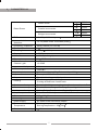
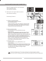
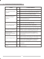
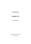
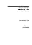
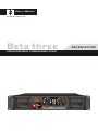
R
User s M anual
ED-B3-MA-060630-001
Beta three
A5/A6/A7/A8
PROFESSIONAL POWER AMPLIFIER
R
BETA THREE
BETA THREE
DEAR CUSTOMERS:
Please carefully read and strictly follow the user's m anual w hen y ou u se A series
professional amplifier. If you have any question, please contact the local dealer.
CATALOGUE
1
Attentions
P1
2
Functions&features
P1
3
Parameters
P2
4
Installation
P6
5
Front panel
P7
6
Rear panel
P7
7
Power supply
P8
8
Input/Output connectors
P8
9
Function setup and cable connection
P9
10
Operations
P11
11
Indicators on front panel
P11
12
Protection functions
P11
13
Troubles and trouble shootings
P12
1
NOTES
High voltage inside the equipment. Do not open the cover. Ask for the help from the
professionals when need servicing.
Please do not expose the equipment in the rain or moisture.
Keep adequate ventilation, do not block the port.
Be sure the voltage of this equipment complies with the local industrial voltage.
Please put off the power plug if unused for a long time.
Please connect rated load. Never working under the overload for a long time.
Symbols:
The equilateral triangle with lightning bolt warns the user of dangerous voltage levels
localized within the cabinet.
The equilateral triangle with exclamatory mark means the important operation on the
user's manual.
2
FEATURES
A series is the amplifier with big power and excellent performance. It can meet
different audio avenues.
1> Big power, 1000W per channel sin power output without distortion under the 8ohms;
2> Innovative heat sink structure and high quality heat sink fan assure working for a long
time;
3> "loading impedance temperature-power-running voltage" can be controlled alternately,
Speed of Fan is automatic adjusted by temperature. When load is too low or temperature
is too high, the equipment can adjust the power supply and lower impedance of power,
which improves sound quality and protect the equipment better. The reliability will be
improved remarkably;
4> Low distortion;
5> High switch speed, >100V/ s, outstanding sound quality and high transparent;
6> Low noise:S/N>108dB(A Weight);
7> Wide frequency band;20Hz~20KHz <+0/-0.25 dB;
8> Small dimension, 2U structure.
1
3
PARAMETERS-A5
Stereo mode
Rated Power
Parallel mono mode
Bridged mono mode
8
160W
4
250W
8
160W
4
250W
4
330W
2
500W
THD
<0.05%(10%Rated power
Intermodulation
distortion
<0.1%(60Hz/7KHz,10%Rated power
Frequency response
20Hz~20KHz(+0/-0.25dB)
Phase difference
Damping factors
< 15
>800(8
Segregation
S/n
>75dB
>108dB(A-Weight)
Total gain
31
Difference of
Channel gain
<0.25dB
Input sensitivity
1V
Switch speed
Input impedance
>50V/ s
Unbalanced input 10K
Input connectors
Three pin XLR/6.35mm
Output connectors
Speakon binding post,NL4 speak
Cooling
Four fans stepless shifting,
Cooling airflow from front to back
Controls on front panel
Switch of AC,Gain controlling knob for channel A and B
Controls on rear panel
Parallel/Stereo/Bridge, LF cutting,Grounding,Limit
Indicator on front panel
Yellow-Bridge,Red-Overload,Green-Signal
Amplifier protection
Short Cirrcuit,Maladjustment of DC,Overload,Overheat ,Etc
Dimensions
Net weight
483 313
12Kg
Power supply
AC 220V/230V,50Hz/60Hz,300VA
Environment
Temperature
Working temperature: -10 ~40
Storing temperature: -25 ~80
Environment humidity
/100Hz)
0.5dB
,Balanced input 20K
88mm
90%
2
3
PARAMETERS-A6
Stereo mode
Rated Power
Parallel mono mode
Bridged mono mode
8
330W
4
500W
8
330W
4
500W
16
660W
8
1000W
THD
<0.05%(10%Rated power
Intermodulation
distortion
<0.1%(60Hz/7KHz,10%Rated power
Frequency response
20Hz~20KHz(+0/-0.25dB)
Phase difference
Damping factors
< 15
>800(8
Segregation
S/n
>75dB
>108dB(A-Weight)
Total gain
34
Difference of
Channel gain
<0.25dB
Input sensitivity
1V
Switch speed
Input impedance
>60V/ s
Unbalanced input 10K
Input connectors
Three pin XLR/6.35mm
Output connectors
Speakon binding post,NL4 speak
Cooling
Four fans stepless shifting,
Cooling airflow from front to back
Controls on front panel
Switch of AC,Gain controlling knob for channel A and B
Controls on rear panel
Parallel/Stereo/Bridge, LF cutting,Grounding,Limit
Indicator on front panel
Yellow-Bridge,Red-Overload,Green-Signal
Amplifier protection
Short Cirrcuit,Maladjustment of DC,Overload,Overheat ,Etc
Dimensions
Net weight
483 382
15Kg
Power supply
AC 220V/230V,50Hz/60Hz,500VA
Environment
Temperature
Working temperature: -10 ~40
Storing temperature: -25 ~80
Environment humidity
/100Hz)
0.5dB
,Balanced input 20K
88mm
90%
5
3
PARAMETERS-A7
Stereo mode
Rated Power
Parallel mono mode
Bridged mono mode
8
660W
4
1000W
8
660W
4
1000W
16
1330W
8
2000W
THD
<0.05%(10%Rated power
Intermodulation
distortion
<0.1%(60Hz/7KHz,10%Rated power
Frequency response
20Hz~20KHz(+0/-0.25dB)
Phase difference
Damping factors
< 15
>800(8
Segregation
S/n
>75dB
>108dB(A-Weight)
Total gain
37.3
Difference of
Channel gain
<0.25dB
Input sensitivity
1V
Switch speed
Input impedance
>80V/ s
Unbalanced input 10K
Input connectors
Three pin XLR/6.35mm
Output connectors
Speakon binding post,NL4 speak
Cooling
Four fans stepless shifting,
Cooling airflow from front to back
Controls on front panel
Switch of AC,Gain controlling knob for channel A and B
Controls on rear panel
Parallel/Stereo/Bridge, LF cutting,Grounding,Limit
Indicator on front panel
Yellow-Bridge,Red-Overload,Green-Signal
Amplifier protection
Short Cirrcuit,Maladjustment of DC,Overload,Overheat ,Etc
Dimensions
Net weight
483 382
18Kg
Power supply
AC 220V/230V,50Hz/60Hz,1000VA
Environment
Temperature
Working temperature: -10 ~40
Storing temperature: -25 ~80
Environment humidity
/100Hz)
0.5dB
,Balanced input 20K
88mm
90%
4
3
PARAMETERS-A8
Stereo mode
Rated Power
Parallel mono mode
Bridged mono mode
8
1000W
4
1600W
8
1000W
4
1600W
16
2000W
8
3200W
THD
<0.05%(10%Rated power
Intermodulation
distortion
<0.1%(60Hz/7KHz,10%Rated power
Frequency response
20Hz~20KHz(+0/-0.25dB)
Phase difference
Damping factors
< 15
>800(8
Segregation
S/n
>75dB
>108dB(A-Weight)
Total gain
39
Difference of
Channel gain
<0.25dB
Input sensitivity
1V
Switch speed
Input impedance
>100V/ s
Unbalanced input 10K
Input connectors
Three pin XLR/6.35mm
Output connectors
Speakon binding post,NL4 speak
Cooling
Four fans stepless shifting,
Cooling airflow from front to back
Controls on front panel
Switch of AC,Gain controlling knob for channel A and B
Controls on rear panel
Parallel/Stereo/Bridge, LF cutting,Grounding,Limit
Indicator on front panel
Yellow-Bridge,Red-Overload,Green-Signal
Amplifier protection
Short Cirrcuit,Maladjustment of DC,Overload,Overheat ,Etc
Dimensions
Net weight
483 452
30Kg
Power supply
AC 220V/230V,50Hz/60Hz,1500VA
Environment
Temperature
Working temperature: -10 ~40
Storing temperature: -25 ~80
Environment humidity
/100Hz)
0.5dB
,Balanced input 20K
88mm
90%
2
4
INSTALLATIONS
43 3
A5:
295
Air
307
482
Flo
w
.4
433
A6/A7:
365
Air
37 7
482
Flo
w
.4
43 3
A8:
425
Air
446
482
6
Flo
.4
w
5
FRONT PANEL
4
5
3
R
BETA THREE
BETA THREE
7
1
1
2
3
4
5
2
6
air input port
signal indicator of channel A
overload indicator of channel A
bridge indicator of channel
overload indicator of channel B
9
6
7
8
9
signal indicator of channel B
power switch
gain adjustment pots of channel A
gain adjustment pots of channel B
REAR PANEL
1
6
2
7
12
CHA
BRIDGE IN
-
!
A
+
INPUT
LF FILTER
MODE
PIN1:
SIGNAL GND
BRIDGE
50HZ
PIN2:
SIGNAL +
PARALLEL
25HZ
PIN3:
SIGNAL -
STEREO
5HZ
CLIPLIMITER
CHA OUTPUT
GROUND
OFF
OFF
ON
ON
OUTPUT ASSIGNMENT:
CHA: PIN 1+ : CHA SIGNAL
PIN 1 - : CHA GND
PIN 2+ : CHB SIGNAL
PIN 2 - : CHB GND
BRIDGE
6
8
CHB: PIN 1+ : CHB SIGNAL
PIN 1 - : CHB GND
PIN 2+ :
PIN 2 - :
BRIDGE MONO OUTPUT:
CHA : PIN1+ : SIGNAL
CHB
3
10
8
1
2
3
4
5
6
7
RMS:
STERO:
BRIDGE:
4
CAUTION
RISK OF ELECTRIC SHOCK
DO NOT OPEN
DELAY
FUSE
T 25A/250V
+
POWER
CABLE
+
AC 220V 50/60Hz
4000VA
B
-
PIN2+ : GND
8 1 000W 2
16 2 000W
41
83
600W2
200W
CHB OUTPUT
ELDER AUDIO MANUFACTORY
5
11
13
14
9
signal input of channel A(XLR JACK)
signal input of channel A(1/4 mic jack)
switch of working modes
limiters
signal output of channel B(binding post)
signal output of channel A(binding post)
fuse
7
8 signal input of channel B(XLR plug)
9 signal input of channel B(1/4 mic jack)
10 filter switch
11 grounding switch
12 signal output of channel A(NL4 JACK)
13 signal output of channel B(NL4 JACK)
14 cable
7
POWER SUPPLY
Please assure the local voltage comply with the voltage indicated on rear panel before
connecting power supply (AC 220V/230V,50-60Hz);
Please assure the cable and jack of power supply not damaged before connecting power
supply; Put off the plug after power off;
8
INPUT/OUTPUT CONNECTORS
Input connectors
The XLR jack and 1/4
microphone jack in same channel are paralleled;
input the signal from either connectors and output the signal for connecting next amplifier;
If the amplifiers connected are too many, the sound quality may be affected;
Please do not input the signal from two connectors in same channel at the same time.
Output connectors
The binding post and NL4 jack in same channel of
UA series
amplifier are paralleled;
Do not connect loads to the two connectors at the same time;
The red end of binding post is connected with anode of speaker, the black end connected
with cathode of speaker;
Just the load suited with the power and impedance of amplifier can be connected
with the output connectors of amplifier.
8
FUNCTION SETUP AND CABLE CONNECTING
As the below drawing, when the switch is ON, the limit is
on, if the input signal is too strong, the limit circuit can
control the gain and reduce the distortion,also control the
average output power,but it not affect peak power, protect
the loudspeaker and assure the daynamic of music.
Note:Please set to "ON" position when using.
When LF cutting is at LF 50Hz,it equals discrete a 50Hz
high pass filter on input,the signal lower than 50Hz will
be accordingly attenuated, then can reduce the
noneffective swing and lower the distortion.
Like the below drawing:
OFF
OFF
ON
ON
LF FILTER
2> LF cutting setup:
CLIP
LIMITER
As the below drawing, when switch is OFF, the limit is off,
the limit circuit is out of work,if input signal is too strong,
output can cause clip distortion and also raise overload on
loudspeaker
CLIP
LIMITER
1> Limiter setup :
50HZ
25HZ
5HZ
+1
0dB
-1
-2
-3
-4
-5
-6 20
When LF cutting is at LF 25Hz, it equals discrete a 25Hz
high pass filter on input circuit, it just attenuate the signal
lower than 25Hz.
Like the below drawing:
30 40 50 60 80 100
200 300
LF FILTER
9
400 500 Hz
50HZ
25HZ
5HZ
+1
0dB
-1
-2
-3
-4
-5
-6
20
9
30 40 50 60 80 100
200
300
400 500 Hz
When LF cutting is at 5Hz, the audio signal
can be amplified really.
Like the below drawing:
LF FILTER
FUNCTION SETUP AND CABLE CONNECTING
+1
50HZ
25HZ
5HZ
0dB
-1
-2
-3
-4
-5
-6
20
30
40 50 60 80 100
200
300 400 500
Hz
3> Mode option and signal cable connection:
Like the below drawing:
Connecting direction:
Stereo connecting mode
Put the switch of mode at stereo,
like the below picture:
MODE
A
BRIDGE
PARALLEL
STEREO
Under the stereo mode, the signal on channel A and
channel B is independent, the signal to channel A is
just for channel A, the signal to channel B is only for
Channel B.Like the below drawing:
B
Mono paralleled mode:
Put the switch of mode at PARALL,like the
below picture:
Nnder the mono paralleled mode, the effect of input
signal from channel A and channel B is same. The
signal on input channel A can be provided to output A,
also to output B. The signal on input channel B not only
provide to output A, also to output B,But please not
input the signal from channel A and B at the same time.
Note: The mono paralleled mode just means the
paralleling of input signal. Never parallel the output
terminals,Like the below drawing:
C
Bridged mode:
Put the switch of mode at BRIDGE,like the
below picture:
Under the bridged mono, signal just can be input from
channel A, no voice if input from channel B, the anode
of output A is the anode of bridged output, the anode
of output B is the cathode of bridged output.
like below drawing:
Under the bridge mode, The output voltage is so high enough to make a
electronic shock. Please power off the unit before operate it under bridge mode.
10
10
OPERATIONS
Please follow the steps during using the equipment
1> Start
a Setup thef unction a nd c onnection a ccording t o t he a bove f unctions etup a nd
connecting;
b Check if the output cable is short circuit and the load is too low;
c Check if the local voltage complies with the user's manual;
d Be sure the switch of power supply at "0" and the volume is the lowest;
e Connect the power supply, turn on the equipment of sound source, pre and effect
equipment and assure these equipments work in order;
f Turn on the switch of power supply(put it at"1"position);
g Adjust the knob of volume clockwise to right position.
2> Off
a Adjust the knob of volume unti-clockwise to the lowest;
b Turn off the switch of power supply on the front panel(put it at "0"position);
c Turn off the pre and effect equipments, sound source equipments;
11
INDICATORS ON FRONT PANEL
1>If signal indicator flashes,it means if there is signal output in two channels;
2>If peak indicator flashes,it means that the input voltage is too high.You should turn
down the volume;
3>If the peak indicator always lights,it means faults.The reason is like this: loading is too
low,short on loading,temperature is too high.You should check it after power off. Turn
on again if no abnormity;
4>If bridge indicator lights, it means that the amplifier is under the bridged mode.
12
PROTECTION FUNCTION
Perfect protection function can prevent the damage for amplifier and speaker
caused by short circuit and output DC and overheat.
1>Short circuit protection: when the load at the output end is short circuit, the equipment
can cut off the signal and protect the equipment;
2>Output DC protection: when the equipment has faults and there is DC in output signal,
the equipment can cut off output automatically and avoid damage for speaker caused
by DC;
3>Overheat protection: If the temperature of heat sink is over the allowed temperature,
the sensor will cut off the output , avoid damage caused by high temperature and
protect he amplifier.
11
13
TROUBLES AND TROUBLE SHOOTINGS
SN
Troublele shooting
1
Check if the power plug and jack are connected well.
2
If the power jack corresponds with 220~240V AC.
3
Check if the fuse on rear panel is broken.
1
Check if the music signal cable is connected well.
2
Check if the power of music source is turned on and
the volume is turned on.
3
If the volume pots is turned on.
1
If the music source output is too big.
2
If the CLIP LIMITER is at the "ON"position.
3
Check if there is any short circuit in output
connectons and if the load is correct. The restart.
1
If the LF FILTER on rear panel is at the LF 50Hz or at
LF 25Hz, setup the switch at appropriate place.
1
Check if the switch of MODE on rear panel is
at the PARALL,please put it at PARALL if it not
at the position.
1
Check check the input signal can compy with voltage,
please enchane the input signal if not sufficient.
2
Check if input SIGNAL voltage is suited,please
enchance the input SIGNAL if not sufficient.
Burning the fuse when start
1
Check the local voltage is same as the voltage of the
equipment.
Others
1
Check if the setup and connection are accordant with
the user manual.
Trouble
No voice,Power indicator
lights off
No voice,Power indicator
Lights,SIG indicator
Light off
CLIP indicator lastslighting
on,Voice is abnormal
The bass is not sufficient
No voice on one
channel under paralleled
mono mode
Output of bridge is too low
12
R
User s M anual
A SERIES
PROFESSIONAL POWER AMPLIFIER