1
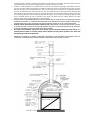
GOLDEN EMBERS GAS FIRED MASONRY OVENS
INSTALLATION AND OPERATING GUIDE
Congratulations! You have chosen one of the finest gas fired brick ovens available in the world today. To ensure that you
enjoy the full benefit of using these extraordinary products, it is essential that you carefully follow all of the steps and
procedures in this operating guide and seek the advice and assistance of your supplier wherever necessary.
Your Golden Embers appliance has been constructed with the finest of refractory materials according to a technically
advanced design based on thousands of years of history. With proper care and the minimum of maintenance, your appliance
should last indefinitely.
We realise that for many the use of wood fire or masonry appliances presents a new challenge and that a certain mystique
has been attached to their usage. We believe that the information presented in this guide and the user manual will dispel any
fears and misconceptions which you may have and enable you to rapidly convert your investment into the profitable centre
piece of a successful eating establishment.
All Golden Embers appliances, whether gas, wood or electric fired, are designed to give long and satisfactory service and
have been fabricated from the best possible materials and workmanship. Nevertheless, proper selection, installation,
adjustment and preventative maintenance is critically important if performance, efficiency and appearance are to
be maintained for the life of the product. Please read all instructions carefully and seek explanations of anything you
may be unsure of, as these instructions contain important safety information regarding the installation, use and
maintenance of the appliance.
Instructions should be read and observed in the following sequence: 1) Any addendum or amended instructions as supplied
with any upgrade or option. 2) Product specific instructions as supplied with the particular primary product 3) Quick
reference operating guides supplied with the principal product 4) Component operating and instruction texts as may have
been supplied 5) The Cooking with Fire Book and finally 6) any third party or additional texts.
PRE-INSTALLATION CHECK LIST
To ensure installation and delivery are quick and simple and that you have selected the correct appliance for your
requirements it is important that you establish and confirm the following items prior to ordering and delivery.
•
•
•
•
•
•
•
•
•
Use the product performance data sheets to establish exactly which product model or variant will satisfy your volume
requirements, having made suitable allowances for planned growth when estimating your requirements.
Select the appropriate fuel type and source and ensure that there is a ready and reliable supply of that fuel.
Check with your local authorities what if any approvals and planning permission’s may be required.
Ensure that you have allowed sufficient space for the appliance to be correctly installed. Allow, if necessary, for any
clearances from structures and adjacent appliances as may be stipulated by the local authorities.
Ensure that there is an access point sufficiently large to allow for delivery and installation of the unit.
Ensure that there is an adequate clear way from the point of unloading to the final position of set down and that the
floor surface is able to bear the weight of the product during installation and positioning.
Check that there is sufficient clearance through doors, and passageways and between other structures and appliances so
as to be able to move the appliance to its set down position in the cooking area.
Ensure that a dedicated flue can be installed in close proximity to the appliance or that appropriate measures have been
taken to enable the flue to be safely connected to an existing extraction system. If a straight flue is to be installed,
check that there are no beams or obstructions in the roof space above the appliance.
Check the type and pressure of any gas supply if the appliance is to be operated on gas. This must be specified prior to
ordering so that the appliance can be configured appropriately for safe and efficient operation.
RECEIVING INSPECTION
•
•
•
•
•
•
Check all crates and packaging for handling damage. After checking for external damage, carefully remove the
external packaging and check for any ‘concealed’ damage.
Report any damage to the carrier immediately it is detected. The carrier may wish to inspect the damage. Remember
that if you did not purchase and pay for transit insurance you are responsible for your own insurance.
If gas or electrical appliance or back up systems are supplied, check the compliance plates to ensure that the correct
appliance for the specified gas or power supply have been supplied.
Care and diligence must be exercised when unpacking, assembling and moving the product.
Special attention must be paid to fire hazards from combustible surfaces and the requirements of the local authorities
and relevant safety or standards authorities must be complied with when positioning the appliance.
When receiving a dome oven the exterior should be inspected in accordance with the finish ORDERED:
If you ordered a kit (Codes PK EK & DK) – there will be no external finish supplied, only several components
If you ordered a raw oven (Codes PZ, EZ & DZ) then the exterior finish is just that –RAW – and you will need to
apply your own render coat and decorative finishes. Raw finish is intended for building in or merely to give a good
starting point from which to apply your own renders and finishes, as such the external finish is not warranted in any
way.
If you ordered a Rendered oven (Codes PR, ER & DR) then an outer render coat has been applied which should
be fairly even, smooth, and structurally sound. This finish is structurally complete and ready for painting or tiling
and is warranted for structural integrity and form on dispatch, ready for the final trims to be applied.
If you ordered a Fully Trimmed or Deluxe Oven (Codes PF EF & DF) then the oven will be delivered fully
trimmed as per the pre-agreed specifications. The tunnel arch will be coloured or tiled and grouted, the outer render
will be encased in a fibre reinforced acrylic render coat and will be coloured or painted to specification and the
mouth will be fitted with a granite mantle. A fully trimmed or deluxe oven is delivered in its final form and can be
used as delivered (once flues etc have been connected). Fully trimmed ovens are warranted to maintain structural
integrity and appearance under proper care and usage for a period of one year after dispatch.
As Golden Embers often ship ovens with a cosmetic appearance that exceeds that of the actual finish ordered, it is
important to remember that the structural finish will only be what was ordered, not what it may appear to be
IF IT IS NOT INVOICED IT WAS NOT ORDERED AND IS NEITHER SUPPLIED NOR SUPORTED
INSTALLATION PROCEDURES
•
PLEASE NOTE – SOME COMPONENTS ARE OPTIONAL AND MAY NOT HAVE BEEN ORDERED OR SUPPLIED
•
Remove the base frame (if purchased) and assemble it. At the lower end of the front and rear frames place the cross members
in the upper holes (110mm from the ground) so that a pallet trolley can fit under them.
Leave the front top cross member of the frame so that the forklift can lower its tines.
Remove the oven from the pallet by getting the fork under the front of the metal base and lifting the oven up several inches. It
may be necessary to break the front board of the pallet away to achieve this
Place two blocks of some sort (about 150mm thick) near the centre of the oven on each side to act as pivot points and lower the
fork. The oven should now be balance some 150mm above the pallet.
Place the tines of the fork under the steel base and lift the oven clear of the pallet. The tines should be set so as to be close
enough to fit inside the frame and should not be inserted further back than about two inches in front of rear framework.
Raise the oven to about 1000mmm above the ground.
Slide the frame under the base and slowly lower the oven so that the locating bolts pass through the matching holes in the top
side members of the frame. Then fasten these bolts to the frame with the nuts and washers.
Lower the tines of the forklift and fasten the top cross member of the front of the frame in position.
Place the tines of the forklift, spread wide as possible, through the frame below the two top cross members.
Now use the forklift to place the appliance inside the premises onto a stable level surface, whether this is through a doorway or
through a window from which the pane of glass has been removed.
If using the turning frame to achieve installation through standard 900mm doorways please carefully read and follow the
instructions supplied separately with the turning frame.
Either use the forklift to move the appliance or place a pallet trolley under the frame and move the unit into position.
At all times ensure that the appliance is only lifted enough to be clear of the floor excess height will result in the appliance
being unstable during movement as it is top heavy.
Once the appliance is in its final position remove the lower cross members and secure them at ground level or secure the side
frames to the floor using dyna bolts and completely remove the front cross member.
If gas back has been purchased, this should be fastened to the frame in the designated position. The exact fixing method
depends on the class of burner purchased and is detailed in the accompanying instructions.
Now connect any gas and power lines and test and commission any burners fitted.
Your plumber or gas fitter should now fit any flues and exhaust ducts and adjust the damper settings.
If a deluxe surround was purchased this should be placed around the frame and fastened to the locating ring ahe girth of the
appliance. If a turret was purchased the upper portion should be fitted above the lower surround and fastened in position.
To build the outer base enclosure, drop plumb line marks from the front corners of the tunnel and then draw a circle of the
appropriate diameter on the floor, which passes through the two plumb points.
Build a brick or other material base up to the level of the render of the oven. Take care at all times to ensure that there is no
contact between the bricks and the steel base of the oven. Keep a gap of at least 10mm at all times. Then render the base (if
desired) to line up with the dome in line with the top of the bricks. Cut a fine v joint in at the union between the top render and
the base. This can be filled with polyfilla high stress or similar before painting or tiling. Finally insert the granite mantle and
decorate to your own taste.
Seal any joints and sponge the colour coating provided over the sealed joints so that they are not visible.
Light the first fire or ignite the gas burner. Although Golden Embers appliances are pre-seasoned, it is still required that the
heat up cycle be progressive. Initially heat the appliance to around 120oC (250oF)and maintain that temperature for around 4
hours. Then raise the temperature in steps of 50 oC (120oF) each four hours.
Ensure that the gas flame does not fire directly into the oven wall and the sub floor burners are run at half power till 120oC
(250oF) is maintained or the start up fire is kept in the centre of the appliance until 300 oC (570oF) has been reached
•
•
•
•
•
•
•
•
•
•
•
•
•
•
•
•
•
•
•
•
•
•
FLUE INSTALLATION REQUIREMENTS
•
•
•
•
•
•
•
•
•
•
•
•
•
•
•
•
•
•
•
•
•
•
•
•
•
•
•
•
All flues fitted to wood fired ovens must now comply with the Australian Standard for solid fuel burning appliances.
Natural draft flues are more than adequate for most wood fire ovens and are the preferred method of extraction for
Golden Embers Ovens and, in Australia, must be installed in accordance with the building regulations applicable to
open fire places in the locality where the oven is installed as well as the solid fuel appliance code.
In general, if a natural draft flue is not able to operate, you will find that there are other environmental airflow
problems which will probable also cause combustion in the fire chamber to be inadequate. You must rectify these
airflow problems rather than merely fix the extraction problem by fitting a fan forced unit.
Smoke is generally only produced when lighting the fire. The fumes thereafter are not unpleasant and should not
aggravate neighbours or statutory authorities. Because Golden Embers ovens use so very little timber compared to
others, they will only produce negligible amounts of smoke at any time. Of course, burning green or wet or resinous
woods will increase the amount of smoke generated by the fire.
Where the fluing is to be directed into existing ducting or communal systems, it is important to ensure that these ducts
do not have an excessive build up of fat. It will also be necessary to fit the oven with a spark-arresting device, such as
Golden Embers Flame and Soot Filter modules so as to eliminate the possibility of sparks being carried into the flues
and igniting any fatty deposits. A fire in the ducting or extraction system of any building can be disastrous. Because of
this, wherever possible, provide a dedicated flue system for the wood fire oven.
The ductwork can become extremely hot and should be insulated wherever it is possible for patrons or staff to touch
exposed sections. This can either be achieved by installing insulated duct-work or after installation by coating ducts in
a vermiculite cement or insulating fire rated material. The standard installation recommended is for the use of a vented
twin skin flue, and, possibly a third (often-decorative) skin in the exposed areas.
All flues must be twin skinned, with a stainless steel inner skin and a vented galvanised steel outer skin.
The standard inner skin used is 8” (205mm) in diameter and the outer skin is 10” (254mm) in diameter.
All penetrations through ceilings must be clear of combustible material and fitted with a non-combustible ceiling ring.
The preferred cowl is a stainless steel wood fired appliance cowl with draft diverter. A directional wood fired cowl can also be
used, if preferred. In some instances you may be required to fit an AGA gas cowl, although these decrease draw and will result
in more rapid build up of wood burning by-products.
The outer duct should be spaced from the inner duct by means of z spacers (or short sections of 1” square tube) at the top and
bottom so as to ensure proper venting and continuous airflow.
A notch should be cut out of the outer duct to allow the damper shaft to penetrate the outer duct. A quadrant, showing open
and closed positions should be fastened over the shaft and fixed to the outer duct. If a third or decorative skin (copper or brass
etc) is fitted then the quadrant should be fixed to the outside of this skin.
If gas is being used then the damper blade must either be 5mm smaller in diameter or have a notch cut off each side so as to
never allow the duct to be sealed.
The outer duct must end about an inch or so lower than the inner duct and should be covered by a skirt cowl or weather
spinning which does not seal it. Alternatively you can use a wood burning twin skin cowl incorporating the outer skirt.
A 10mm high gap must be left at the foot of the second skin to allow airflow through the inter-skin gap.
The inner skin must be fitted with a steel butterfly damper with a long shaft that penetrates the second skin. Don’t use
aluminium cast dampers – they warp and fall out. Use fixed shaft steel or galvanised metal dampers only.
The damper must be adjusted so that air is only just drawn into the flue. If the draw is too strong, heat will be drawn
from the cooking chamber combustion will be excessive, wasting fuel and creating more soot.
If gas is fitted then the damper must either be undersized or have cut-offs to prevent absolute closure of the flue.
The damper shaft must be fitted with a lockable quadrant which shows open and closed positions.
The roof penetration must be sealed with an appropriate approved aquaseal or deck-tite. The black type is generally adequate
for twin skin flues, although the pink or red types are sometimes preferred by the AGA.
A Golden Embers flue kit, containing all of the required elements for a straight flue to 4m is available for $325.00 additional
straight sections are available for $50 per length of 900mm. (As at September 1998)
Flues must clear the roof by at least 600mm and preferably 1200mm. The cowl must be at least 4m away from the nearest
point higher than the outlet venting point.
Where the flue protrudes more than 1200mm above the roofline, particularly in exposed weather situations, stay lines may be
required to secure the flue and maintain rigidity and stability.
Where the flue is in close proximity to timbers in the ceiling space etc, the flue has been wrapped in insulating blanket, either
25mm ceramic blanket (where the exposed timbers are highly flammable) or 50mm CSR Fibretex R350.
Avoid bends and horizontal sections as far as possible and where they are absolutely necessary use 45 degree or lesser bends as
opposed to ninety degree or sharper bends. Preferably use radius or lobster back bends as opposed to sharp bends. Where there
is any significant extent of horizontal flue it is recommended that an inspection hatch be incorporated into the flue at the start
ane end of any horizontal section to facilitate cleaning and maintenance.
All bends and horizontal sections must be readily removable or fitted with inspection hatches and/or cleaning elbows.
To minimise the risk of fire, it is recommended that the flues are cleaned at least annually, to remove any soot and other build
up of flammable materials, although, in reality, you will find these to be negligible if the correct timbers are used. It is
advisable to have the flue inspected after six months of operation to establish what degree of build up has occurred. Where
there are any horizontal sections then it is required that the flues be inspected and cleaned more regularly.
The design of the oven, tunnel and flue outlet is such as to make it near impossible for any sparks to enter the flue shaft during
normal operation of the ovens. Nevertheless, where the flue is to be vented into a general or communal extraction system, it is
•
•
•
•
•
recommended that a stainless steel baffle element filter be incorporated into the transition flue inlet and that a break be
incorporated into the flue at the point of coupling, effectively creating a miniature range hood.
All flame is contained within the oven chamber and has to move out of the chamber at right angles to the induced convection
flow, around a 45mm right-angled protruding lip. Thereafter, all flue gasses must move through the incoming fresh air stream,
effectively inducing a vortex scrubbing effect, mix with an at least equal portion of fresh air, turn at right angles again and
move into the horizontal section of the transition flue, once again change direction at right angles, before entering the flue
shaft. Effectively this means all flue material moves through 320 degrees, around 4 bends, through one induced vortex and
over two differing materials, before it entering the flue shaft. This design is far more effective at eliminating spark travel than
the two horizontal offset strips used in competitive units (which vent directly from the cooking chamber), and which
effectively put the air flue gasses through only two 45 degree bends.
Should you wish to add additional filtration, then a twin baffle insert can easily be fitted from galvanised sheet and
riveted into the transition, or, a stainless flame mesh filter can be fabricated to fit into the transition intake opening.
If the flame filter insert is used, it will need to be cleaned extremely regularly so as not to obstruct the airflow.
All flues must be professionally cleaned at least annually. Where bends or horizontal sections exist in the flue,
or the flue vents into a common duct where fatty deposits may exist, it is recommended that they be cleaned six
monthly and all bends should be then fitted with inspection hatches
The exact interval between cleaning for each specific system should be determined under advice of a
professional flue cleaner or chimney sweep and will depend on many factors specific to the actual site
and operating conditions and practices.
IMPORTANT! - REFER AT ALL TIMES TO THE CODE APPLICABLE TO THE AUSTRALIAN STANDARDS OR LOCAL
AUTHORITY STANDARDS FOR SOLID FULE BURNING APPLIANCE FLUES AND INSTALLATION.