1
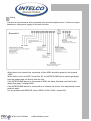
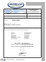
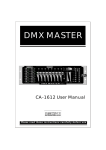
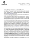
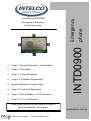
Page 2 General Description - Compatibility Page 4 Connection Page 5 Filter false alarms Page 6,7,8,9 Basic Programming Special Operations Programming Page 10 Functional Description Page 11 Test installation - EU Compliance Page 12,13,14 Certifications INTD0900 Emergency Call System for elevator using Emergency phone User Manual INTD0900 Please read carefully the instructions in order to get all the benefits of this device. INTELCO ELECTRONICS ISO9001/2008 member www.intelco.com.gr Version history V5.3 07/2011 add commands #090 #091 #092 V5.4 V5.5 V5.6 06/2012 for factory use V5.7 06/2012 add command #093 V5.8 11/2012 add command #094 V5.9 v6.0 06/2013 for factory use V6.1 02/14 add command #095 change function for remote control operation General Description: The INTELPHONE device with code INTD0900 Light is an electronic device which can call up to 4 ( four ) predefined numbers in case of emergency in elevators. The device is placed in the elevator car and can achieve two-way communication between the trapped passenger and the rescue service. The INTELPHONE does not require another power source apart from the telephone line, in order to operate. Caution : The installation and setting of the device, must be done by qualified personnel . The device is designed to meet the requirements of the European Directive EN 81-28 for safety in lifts. Requirements of the standard EN81-28: The INTELPHONE device must be connected to an authorized agent or to an Emergency Call Center. • Provide to the Emergency Center all the necessary information for the installation in the building. The lift must be set out of order when the device is not connected to an Emergency Center. Periodically check the correct functioning of the device. 2 INTELCO ELECTRONICS ISO9001/2008 member Wring: The device is autonomous and is powered only from the telephone line. It does not require batteries or other power supply for its basic function. Scematic1 When there is an Internet line connected, a filter ADSL should be placed in the terminal “LINE” . When there is a line of VOIP (Voice Over IP), the INTELPHONE device should get signal from the modem and not directly from the line. If the INTELPHONE device is connected to ISDN, the delay dismissal must first be disabled (See page 7 setting # 082). If the INTELPHONE device is connected to an internal call center, a full operational control must be made. For any problem call SERVICE: phone 0030 210 23 23 345 / internal 221. 3 INTELCO ELECTRONICS ISO9001/2008 member Filter False Alarms: The device with the proper connection ( Figure 2 ) may reject false alarms . There are two cases of false alarm. The first is when the elevator moves and is about to stop normally and the second is when the elevator stops on a floor while the door is open . To enable the device and make the filter operate, an input voltage of 12 or 24 volt should be given on the terminals INPUT of the device ( Figure 2 ) . When there is an input voltage of 12 or 24 volt the device is unable to make any calls. The voltage input must be provided by the control panel of the lift. When the lift is in maintenance mode no interference call can be handled by the filter. Figure 2 4 INTELCO ELECTRONICS ISO9001/2008 member Basic Programming: The device has a keyboard attached for the programming operation. A connection with a telephone provider is necessary in order to programm the device. As another option, a 9-12VDC battery connected to terminal “LINE” of device, can be used. By pressing PR (PROGRAM) abbreviation on the keyboard, the yellow LED turns on and the unit enters the programming mode . To continue the programming, the password 0000 (default setting) should be stored. Using the parameter # 089 the password can be changed to the one of your choice . There is no need to change the password to continue programming the device. After each accepted command the device informs the user with two (2 ) beeps . After each setting the device remains open and stands by a new command. Press the PR button to close the programmed device. Programming & Saving Station Numbers : The telephone numbers that have been formed will be stored in the internal memory of the device, in certain locations (M1, M2, M3, M4) according to the following order. memory 1 (M1) S1 2102323345S memory 2 (M2) S2 2102323345S memory 3 (M3) S3 199S memory 4 (M4) S4 6900000000S In case of mishandling during the process of storing the telephone numbers press the PR button to close the device and repeat the procedure from the beginning. The memory locations will be holding four different numbers. If only one number will be used, it must be stored in each one of the four locations. 5 INTELCO ELECTRONICS ISO9001/2008 member Special Operations Planning: To begin the Special Operations Planning first press the PR button to open the device. The yellow indicator LED must be turned on. If the device is connected to the GSM IND0909, you must do all the necessary settings and next press the code # 093. When the programming is finished and the device is still open, press the PR button to close it and wait for at least 2 seconds (2sec) until it is deactivated. Special Operations Programming Code Setup Description Password #015 Setting device when the line comes from PBX or GSM. The device will close only after two seconds (2sec). #080 Adjust speaker volume. Button “1” increases tension, “2” reduces volume. After the desired setting, press * to save. Factory regulation 50% #080 1 1 1 1 * or #080 2 2 1 2* #081n Number of rings to answer an incoming call. n = a number from 0 to 9.The number indicates how many times the device will ring before answering. By placing the device number 0 is not answered #0813* need 3 rings to answer #082 Configuring ISDN (off delay dismissal). The device opens and automatically dials the code ** 71 # to cancel the delayed dismissal. The device will send signal (OK) after one (1) second (sec). #083 Configuring ISDN (acceptance time flash). The device opens automatically dials the code * 25 ** # 20 to set the flash acceptance time less than 200 msec. The apparatus sends a signal (OK) after one (1) second (sec). 6 INTELCO ELECTRONICS ISO9001/2008 member 1 Special Operations Programming Code Setup #084x Description Password Option termination call during communication. x= * The user has the option to terminate the call, during communication (green LED lit) if the button is pressed for more than 3 seconds. Factory setting Function deactivated # x= # The option is disabled. The call will terminate after 3 minutes or soon as it receives a busy tone #085x Select accepting filter. Function deactivated # x=* The user has the ability to activate the filter input and intervene in it as specified by regulation. x=# The option is disabled. #086x Select AutoShip ID authentication device INTELPHONE. Function deactivated # x = * Automatically sending ID identity of the device when in state speech (speak). x = # The option is disabled. The device will send 4 digit DTMF tones . #088nnnn Change the ID device of the INTELPHONE. nnnn = 4 numbers which will represent the new identity (ID) of the device. 0000 #089nnnn Change password on device settings INTELPHONE. nnnn = 4 numbers which will represent a password on device settings. When the code is 0000 it is not required to be dialed, in order to make any settings. If the password is changed, the introduction is necessary. If the entered password is false the device disconnects automatically. 0000 #090x Select tone or pulse system. Tonal system x = * Pulsed system on. <#> x = # Tonal system on. 7 INTELCO ELECTRONICS ISO9001/2008 member Special Operations Programming Code Setup #091n Description Password Number of seconds between the 1st and the 2nd digit of the dialed number. n = Any number from 1 to 9.The number indicates how many seconds will elapse between the first and second place when the device is connected to a telephone center. Factory setting <1> #092n Call waiting time. n = Any number from 1 to 9.The number indicates how many callings take place until the next call (IF the first call is not answered). #093x Option for connection and operation with theGSM INTD0909 device. x = * Function activated. x = # Function deactivated. Before performing any adjustment, wait until you hear 2 beeps (OK). All memory stored in the Intelphone, will be copied to the GSM’s simcard. All calling progress (busy, not answer and mobile provider ) will be moderated from the GSM INTD0900 microcontroller for more flexibility CAUTION: Valid only for the devices starting from S/N5326i and over. Function deactivated Confirmation of acceptance of the call from the rescue service. If this function is activated the rescuer must accept the call and confirm it by pressing *1* within 15 sec. If it is not confirmed within 15 sec, the device will call the next memory number. After the call is accepted and confirmed using the code *1* , to terminate the call the rescuer must press *1#. During the confirmation some extra options are available. *1# terminate the call *2* ask for the ID of the device *3* activate the dry contact relay *3# deactivate the dry contact relay *4* activate function for momentary use of the relay As long as 4 is pressed the relay is activated and soon as it is released the relay deactivates. CAUTION: Valid only for devices with the “ia” sign added to the serial number. Function deactivated #094x #095n n=Number of seconds needed for the PR button to be pressed until the emergency call is deactivated. 8 INTELCO ELECTRONICS ISO9001/2008 member <6> <#> <#> 3 Special Operations Programming Code Setup #096x #08i Description Password Option for connection and just make phone line as “off Hook”. Useful when Intelphone working as ‘ext” line of an building phone center PABX x = * Function activated. x = # Function deactivated. Default deactivate. Factory setting Function deactivated <#> Restore factory settings. Restores the factory settings of the device and removes all stored numbers from the memory . Description of Operation: The main function of INTELPHONE is divided in two main sections as described below . A : Automatic connection to the rescue service by pushing a button : Press and hold the button labeled “PHONE” for four seconds (4sec). The yellow indicator LED will turn on and start the automatic dialing of stored numbers. The device dials first the emergency number stored in position 1 ( M1) . If the number is busy or does not answer, the device starts dialing the next stored number and so on. The above procedure is repeated three (3 ) times consecutively numbered M1, M2, M3 and M4 . On condition that the twelve (12 ) attempts fail , the device will shut off and you must repeat the process . B: Automatic operation control command : The elevator control system or any other electronic system can automatically start the same connection as described in < A > by applying voltage 12 volt contacts CONTROL device ( See page 4 Figure 1). CAUTION : Using the jumper NO / NC (located between terminals CONTROL and SPEED trimmer) the following functions can be selected: In place NO starts if we give 12 volt voltage terminals CONTROL. In place NC starts if interrupted power supply 12 volt terminals of CONTROL. Accepting an external call : The device can accept external calls from other phones . The device answers the call if desired after a preselected number of rings (see page 8 setting # 094x) and remains in line for six (6 ) minutes . CAUTION : The INTELPHONE will not ring when accepting an external call, so the person who makes the call should start talking first. The INTELPHONE device will not operate properly if it is connected to an answering machine terminal. 9 INTELCO ELECTRONICS ISO9001/2008 member Test before startup: The installer must do the test after installation. Tests before starting operation should cover the operation of the alarm system. The control and test of the entire system must be in accordance with relevant standards of series EN 81. Compliance EU: Directive 99/5/EC describes <At the discretion of the manufacturer, the device's conformity with the essential requirements specified in Article 3 (1) (a) and (b) can be demonstrated using the procedures set out in Directives 73/ 23/EEC and 89/336/EEC. >. The telecommunication devices which do not use radio spectrum - telecommunications and can take part information should be subject to the procedures described in any of the Annexes II, IV or V at the discretion of the manufacturer. On standards harmonics: CONDITION CONFORMITY CERTIFICATION BODIES EMISSION EN 55022/ΕΝ12015 Anco Lab 1/12/2003 VULNERABILITY EN 55024/ΕΝ12016 Anco Lab 1/12/2003 ESD EN 61000-4-2 EMC HELLAS 0044 15/09/2003 INJECT CURRENT EN 61000-4-6 EMC HELLAS 0044 15/09/2003 MAGNETIC FIELD EN 61000-4-8 EMC HELLAS 0044 15/09/2003 CONTINUOUS NOISE EMISSION EN 61000-4-3 Anco Lab 1/12/2003 WAVE TRANSMISSION EN 61000-4-5 EMC HELLAS 0044 15/09/2003 FAST TRANSIENT EN 61000-4-4 EMC HELLAS 0044 15/09/2003 For electromagnetic compatibility (Directive 89/336/EEC) For safety (Directive73/23/EC) ANCO SA 20/12/2003 EN 60950 § 2.1.4,2.2.3,6.1,6.2,6.2.1,6.2.1.1,6.3.1,6.3.2 For efficiency, Certificate No. 2667 17/10/2003 OTE SA TBR21, TBR38 KAI ETS300-001. For EN 81-28 4,5,6 & 7 EVETAM LF/AC-1155/09. 10 INTELCO ELECTRONICS ISO9001/2008 member DECLARATION OF CONFORMITY ΔΗΛΩΣΗ ΣΥΜΜΟΡΦΩΣΗΣ Manufacturer’s Name E. PELEKIS and Co Manufacturer’s Address Hr. Karvouni 27- AHARNAI Declares that the product: Emergency Lift Telephone Product Name: “ SERIALNumber(s): FROM INTELPHONE” TO Product types : INTD0900/ ATED0900 Conforms with the essential requirements of the emc directive 89/336/EC and the Radio & Telecommunications Terminal Equipment directive 1999/5/EC and satisfies all the applicable standards to the product within this directives as follows: Emission Vulnerability ESD EN 55022/ΕΝ12015 EN 55024/ΕΝ12016 EN 61000-4-2 Inject Current Magnetic Field Continuous noise emission Fast transient Wave transmission EN 61000-4-6 EN 61000-4-8 EN 61000-4-3 EN 61000-4-4 EN 61000-4-5 EN81-28 TBR21 , TBR-38 ETS300-001 article 3.1a / άρθρο 3.1α: PERFORMED/ΕΦΑΡΜΟΣΤΗΚΕ article 3.1b / άρθρο 3.1β: PERFORMED/ ΕΦΑΡΜΟΣΤΗΚΕ Date and location/ ATHENS 2/11/2004 Signature /Υπογραφή 11 INTELCO ELECTRONICS ISO9001/2008 member 12 INTELCO ELECTRONICS ISO9001/2008 member