1
autoSV
TM
with
Encore SmartCard®
Provider Manual
This BiPAP system is covered by one or more of the following patents: U.S. Patent Nos. 5,148,802; 5,239,995; 5,313,937;
5,433,193; 5,632,269; 5,803,065; 6,029,664; 6,305,374 and 6,539,940; Australian Patent Nos. 638054; 661575; 698519;
723681; 734319 and 733655; Canadian Patent Nos. 2,024,477; 2,162,981 and 2,259,795; European Patent No. EP0425092;
German Patent No. 69021681.5-08; and Japanese Patent Nos. 2832812; 2137336; and 2926392. Other U.S. and foreign
patents pending.
© 2007 Respironics, Inc. and its affiliates. All rights reserved.
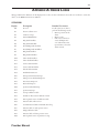
Table of Contents
Chapter 1: Package Contents.......................................................................................................................................1-1
Chapter 2: Warnings and Cautions.............................................................................................................................2-1
2.1 Warnings............................................................................................................................................2-1
2.2 Cautions.............................................................................................................................................2-3
2.3 Intended Use.....................................................................................................................................2-3
2.4 Contraindications............................................................................................................................2-3
2.5 Patient Precautions..........................................................................................................................2-4
Chapter 3: Introduction..............................................................................................................................................3-1
3.1 Overview............................................................................................................................................3-1
3.2 Operation...........................................................................................................................................3-1
3.2.1 Pressure Controls..................................................................................................................3-2
3.2.2 Back-up Breath Rate Controls..............................................................................................3-3
3.2.3 Ramp..........................................................................................................................................3-5
3.2.4 Digital Auto-Trak Sensitivity................................................................................................3-5
3.3 Access Levels......................................................................................................................................3-7
3.3.1 Provider Mode Access Level..................................................................................................3-7
3.3.2 User Mode Access Level.........................................................................................................3-8
3.4 Definitions, Acronyms, and Abbreviations....................................................................................3-9
3.5 Symbol Key ........................................................................................................................................3-10
3.6 Service...............................................................................................................................................3-10
Chapter 4: Controls and Displays...............................................................................................................................4-1
4.1 Controls and Displays......................................................................................................................4-1
4.1.1 Display Screen.........................................................................................................................4-1
4.1.2 Control Buttons....................................................................................................................4-3
4.1.3 Indicators.................................................................................................................................4-4
4.1.4 Audible Alarms and Indicators.............................................................................................4-4
4.2 Navigating the Screens....................................................................................................................4-4
4.2.1 LED Backlight for Buttons...................................................................................................4-5
4.3 Patient Circuit Connection............................................................................................................4-5
4.4 Rear Panel..........................................................................................................................................4-5
4.5 SmartCard..........................................................................................................................................4-6
Chapter 5: Setup............................................................................................................................................................5-1
5.1 Preparing the Device........................................................................................................................5-1
5.1.1 Installing the Air Filters.......................................................................................................5-1
5.1.2 Assembling the Patient Circuit.............................................................................................5-1
5.1.3 Supplying Power to the Device..............................................................................................5-2
5.1.4 Startup......................................................................................................................................5-3
5.1.5 Entering Provider Mode........................................................................................................5-5
5.1.6 Performance Verification......................................................................................................5-5
5.2 Setting up the Device.......................................................................................................................5-5
5.3 Connecting the Patient...................................................................................................................5-6
5.4 Setting up the SmartCard................................................................................................................5-6
5.4.1 Downloading Data..................................................................................................................5-6
5.4.2 Programming a SmartCard.....................................................................................................5-6
5.4.3 Changing Settings Using a SmartCard................................................................................5-6
Chapter 6: Changing Settings.....................................................................................................................................6-1
6.1 Changing Settings in Provider Mode............................................................................................6-1
6.1.1 Navigating Screens in Provider Mode..................................................................................6-1
6.1.2 Changing Settings in Provider Mode..................................................................................6-2
6.2 Monitoring Measured Parameters ..............................................................................................6-8
6.3 Changing Settings in User Mode...................................................................................................6-10
Provider Manual
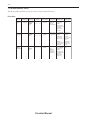
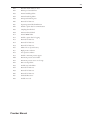
Chapter 7: Alarms..........................................................................................................................................................7-1
7.1 Alarm Introduction.........................................................................................................................7-1
7.1.1 Overview of Alarm Behavior.................................................................................................7-1
7.2 System Alarms....................................................................................................................................7-3
7.2.1 System Error Alarm................................................................................................................7-3
7.2.2 Card Error Alarm...................................................................................................................7-3
7.2.3 Pressure Regulation High Alarm..........................................................................................7-4
7.2.4 Pressure Regulation Low Alarm............................................................................................7-4
7.2.5 Low Pressure Support Alarm.................................................................................................7-4
7.2.6 Prescription Complete Alarm................................................................................................7-4
7.3 Patient Alarms...................................................................................................................................7-5
7.3.1 Apnea Alarm.............................................................................................................................7-5
7.3.2 Patient Disconnect Alarm.....................................................................................................7-5
7.3.3 Low Minute Ventilation Alarm.............................................................................................7-6
7.4 Power Alarms.....................................................................................................................................7-7
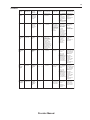
7.5 Alarm Summary Tables........................................................................................................................7-8
Chapter 8: Cleaning and Maintenance.......................................................................................................................8-1
8.1 Cleaning the Device.........................................................................................................................8-1
8.1.1 Cleaning and Disinfection for Multiple Users..................................................................8-1
8.2 Cleaning or Replacing the Inlet Filters.......................................................................................8-1
8.3 Maintenance......................................................................................................................................8-2
8.4 Carrying Case....................................................................................................................................8-2
Chapter 9: Adding Supplemental Oxygen...................................................................................................................9-1
9.1 Adding Supplemental Oxygen..........................................................................................................9-1
9.2 Supplemental Oxygen Concentrations...........................................................................................9-2
Chapter 10: Circuits and Accessories.........................................................................................................................10-1
10.1 Circuit Configurations..................................................................................................................10-1
10.2 Circuits and Accessories................................................................................................................10-1
10.3 Masks, Exhalation Ports, and Related Accessories.....................................................................10-2
10.4 Humidifiers......................................................................................................................................10-2
10.5 Software...........................................................................................................................................10-2
Chapter 11: Operational Verification.........................................................................................................................11-1
11.1 System Verification.........................................................................................................................11-1
11.2 Alarm Verification..........................................................................................................................11-2
Chapter 12: Specifications............................................................................................................................................12-1
Appendix A: Error Codes...............................................................................................................................................A-1
Appendix B: EMC Information.....................................................................................................................................B-1
Provider Manual
1-1
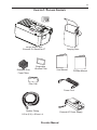
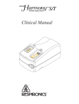
Chapter 1: Package Contents
BiPAP autoSV with
Encore® Pro SmartCard™
Reusable Gray
Foam Filters
Disposable
Ultra-fine Filter
Carrying Case
User Manual
Provider Manual
Filter Cap
Power Cord
Flexible Tubing
1.83 m (6 ft.) x 22 mm i.d.
Provider Manual
External AC Power Supply
1-2
Provider Manual
2-1
Chapter 2: Warnings and Cautions
WARNING:
Indicates the possibility of injury to the patient or the operator.
CAUTION: Indicates the possibility of damage to the BiPAP autoSV device.
NOTE: Places emphasis on an operating characteristic.
Caution:
U.S. federal law restricts this device to sale by or on the order of a physician.
2.1 Warnings
•
•
This manual serves as a reference. The instructions in this manual are not intended to supersede the instructions of
the health care professional.The operator should read and understand this entire manual before using the device.
Long term effects of the treatment of sleep disordered breathing and/or Cheyne Stokes Respiration in patients with
Congestive Heart Failure (CHF) or atrial fibrillation have not been documented. Therefore, caution should be
exercised when using this device on a patient with CHF or atrial fibrillation. The clinician should assess the relative
risk and benefits of the therapy on a case-by-case basis.
The device provides positive pressure ventilation and is indicated for assisted ventilation. This system does not
provide ventilation with guaranteed tidal volume delivery. Patients requiring ventilation at predetermined tidal
volumes are not candidates for pressure support ventilation.
This is not a life support ventilator. BiPAP autoSV is a non-continuous ventilator intended to augment patient
breathing. It is not intended to provide total ventilatory support. It may stop operating with power failure or if a
fault occurs in the product.
In the event of a power or device failure, audible and visual alarm signals will activate. The device must then be
disconnected from the patient immediately. As is the case with most ventilators with passive exhalation ports, when
power is lost, sufficient air will not be provided through the circuit, and exhaled air may be rebreathed.
At low EPAP pressures, the flow through the exhalation port may be inadequate to clear all exhaled gas from the
tubing. Some rebreathing may occur. Monitor the patient appropriately.
To reduce the risk of contamination, you may place a bacteria filter in-line between the device and the patient.
The device does not have an alarm to detect occlusion of the exhalation port. Before each use, inspect the patient
circuit to verify that the port is not occluded. Occlusion or partial occlusion can reduce airflow and result in
rebreathing of exhaled air.
Verify the operation of the Patient Disconnect alarm with any changes in the patient circuit.
•
Verify that the Patient Disconnect alarm is active if required for medical reasons.
•
If the patient has a severe obstructive or restrictive spirometric defect, or severe daytime hypercapnia or hypoxia,
then the device may not be an appropriate treatment method. This is due to the level of ventilatory support that the
device provides.
Do not connect any equipment to the device unless recommended by Respironics or the health care professional.
Verify that an exhalation port is present to exhaust CO2 from the circuit. If circuit accessories other than those
recommended by Respironics are connected to the device, then pressure must be verified. Use of these accessories
may alter the pressure received, reducing the effectiveness of treatment.
•
•
•
•
•
•
•
•
•
The device should be used only with masks and accessories recommended by Respironics or with those
recommended by the health care professional or respiratory therapist. See Chapter 10 for approved patient circuits.
A mask should not be used unless the device is turned on and operating properly. The exhalation port(s) associated
with the mask should never be blocked. In the event of a power failure or machine malfunction, remove the mask.
Explanation of the Warning: The device is intended to be used with special masks or connectors that have
exhalation ports to allow a continuous flow of air out of the mask. When the device is turned on and functioning
properly, new air from the device flushes the exhaled air out through the mask exhalation port. However, when the
device is not operating, enough fresh air will not be provided through the mask, and exhaled air may be rebreathed.
Rebreathing of exhaled air for longer than several minutes can in some circumstances lead to suffocation.
Provider Manual
2-2
•
Operation of the device may be adversely affected by:
– Electromagnetic fields exceeding the level of 10 V/m in the test conditions of
EN 60601-1-2
– Operation of high frequency (diathermy) equipment
– Defibrillators, or short wave therapy equipment
– Radiation (e.g., x-ray, CT)
– Magnetic fields (e.g., MRI)
•
Do not use the device at room temperatures above 95° F (35° C). If the device is used at room temperatures above
95° F (35° C), the temperature of the airflow may exceed 106° F (41° C), which could cause thermal irritation or
injury to the patient’s airway.
•
Do not operate the device in direct sunlight or near a heating appliance because these conditions can increase the
temperature of the air coming out of the device.
Do not use antistatic or electrically conductive hoses or tubing with the device.
When the device is used with an external humidifier, position the humidifier so that the water level in the humidifier
is lower than the patient and the humidifier is on the same level or lower than the device. Use only Respironicsapproved humidifiers with the BiPAP autoSV.
If you detect any unexplained changes in the performance of the device, if the device is dropped or mishandled, if
water is spilled into the enclosure, or if the enclosure is broken, seek the assistance of Respironics or an authorized
service center.
Do not open the BiPAP autoSV enclosure. There are no user serviceable parts inside. Repairs and internal servicing
should only be performed by an authorized service agent.
Electrical cords and cables should be periodically inspected for damage or signs of wear. Replace any damaged parts
before using.
To avoid electrical shock, unplug the device before cleaning.
•
•
•
•
•
•
•
Pins of connectors identified with the ESD warning symbol should not be touched. Connections should not be
made to these connectors unless ESD precautionary procedures are used. Precautionary procedures include methods
to prevent build-up of electrostatic discharge (e.g., air conditioning, humidification, conductive floor coverings,
non-synthetic clothing), discharging one’s body to the frame of the equipment or system or to earth or a large metal
object, and grounding oneself by means of a wrist strap to the equipment or system or to earth.
•
If oxygen is used with the device, the oxygen flow must be turned off when the device is not in use.
Explanation of the warning: When the device is not in operation and the oxygen flow is left on, oxygen delivered
into the ventilator tubing may accumulate within the device’s enclosure. Oxygen accumulated in the ventilator
enclosure will create a risk of fire.
•
When using oxygen with this system, a Respironics Pressure Valve must be placed in-line with the patient circuit.
•
•
Oxygen supports combustion. Oxygen should not be used while smoking or in the presence of an open flame.
When administering fixed-flow supplemental oxygen, the O2 concentration may not be constant. The inspired
oxygen concentration will vary, depending on the IPAP and EPAP pressures, patient breathing pattern, and the
leak rate. Substantial leaks around the mask may reduce the inspired oxygen concentration to less than the expected
concentrations. Monitor the patient appropriately.
•
To prevent an accumulation of oxygen in the device, advise the patient to turn the device on before turning on the
oxygen. Likewise, the patient must turn off the oxygen before turning off the device.
•
Do not use the device in the presence of a flammable anaesthetic mixture in combination with oxygen or air, or in
the presence of nitrous oxide.
Provider Manual
2-3
2.2 Cautions
• The device may only be operated at temperatures between 41° F (5° C) and 95° F (35° C).
• Do not immerse the device or allow any liquid to enter the enclosure or the inlet filter.
• Do not place the device in or on any container that can collect or hold water.
• Condensation may damage the device. Always allow the device to reach ambient temperature before use.
• Use the power cable retainer to keep the power cord from being unintentionally disconnected.
NOTE:
Additional warnings, cautions, and notes are located throughout this manual.
2.3 Intended Use
The BiPAP autoSV is intended to provide non-invasive ventilatory support to treat adult patients with OSA and Respiratory
Insufficiency caused by central and/or mixed apneas and periodic breathing.
2.4 Contraindications
The BiPAP autoSV system should not be used on patients with the following conditions:
•
•
•
•
•
•
•
•
•
•
•
•
•
•
Patients without a spontaneous respiratory drive
Existing respiratory failure (failure to treat; risk of increased work of breathing due either to incomplete reversal of
upper airway obstruction or to breathing at high lung volume, leading to worsening respiratory failure)
Pneumothorax or pneumomediastinum
Emphysematous bullae or a past history of pneumothorax (risk of pneumothorax)
Acute decompensated cardiac failure or hypotension, particularly if associated with intravascular volume depletion
(risk of further hypotension or reduction in cardiac output)
Massive epistaxis or previous history of massive epistaxis (risk of recurrence)
Pneumoencephalus, recent trauma or surgery (e.g., pituitary or nasal) that may have produced cranionasopharyngeal fistula (risk of entry of air or other material into the cranial cavity)
Acute sinusitis, otitis media, or perforated ear drum
Acute or unstable cardiac failure
Nocturnal or resting angina (risk of infarction or arrhythmias)
Unstable arrhythmias
Severely obtunded or heavily sedated patients
At risk for aspiration of gastric contents
Impaired ability to clear secretions
If patients are dehydrated or volume depleted, or have persistent atrial fibrillation, their cardiac filling pressures may be
low. In these cases, as with any CPAP or ventilatory support, use of the device may lead to a dangerous reduction in cardiac
output. The device should not be used in patients who are dehydrated or volume depleted, and should be used with extreme
care in patients with atrial fibrillation.
NOTE:
When assessing the relative risks and benefits, the health care professional should understand that the device can
be set to deliver pressures up to 30 cm H2O. Also, in the unlikely event of certain fault conditions, a maximum
static pressure of 40 cm H2O is possible.
Provider Manual
2-4
2.5 Patient Precautions
•
The following are potential side effects of noninvasive positive pressure therapy:
— Ear or sinus discomfort
— Conjunctivitis
— Skin abrasions due to noninvasive interfaces
— Gastric distention (aerophagia)
— Drying of nose, mouth or throat
— Eye irritation
— Skin rashes
— Chest discomfort
Provider Manual
3-1
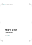
Chapter 3: Introduction
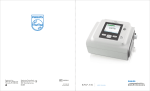
3.1 Overview
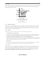
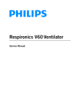
Figure 3-1 The BiPAP autoSV Device
The device, shown in Figure 3-1, is a low-pressure, electrically driven ventilator system with electronic pressure control. The
device’s pressure controls are adjusted to deliver pressure support for patient ventilatory assistance.
The device is intended to augment patient breathing by supplying pressurized air through a patient circuit. It senses the
patient’s breathing effort by monitoring airflow in the patient circuit and adjusts its output to assist in inhalation and
exhalation. This assistance is provided by the administration of two levels of positive pressure. During exhalation, pressure
is variably positive or near ambient. During inspiration, pressure is variably positive and always equal to or higher than the
expiratory level.
The device responds reliably to patient flow rates that indicate movement to inhalation or exhalation, even in the presence
of most normal leaks in the patient circuit. Automatic adjustment of this trigger threshold in the presence of leaks makes
the system ideal for mask-applied ventilation assistance. The patient-controllable Rise Time feature may enhance patientventilator synchrony and patient comfort.
3.2
Operation
This section provides information on the following BiPAP autoSV features:
•
•
•
•
Pressure Controls
Back-up Breath Rate Controls
Ramp
Digital Auto-Trak™ Sensitivity
Provider Manual
3-2
3.2.1
Pressure Controls
The device contains the following controls which are used to configure positive pressure therapies:
•
•
•
EPAP – The pressure maintained during expiration.
IPAP Min – The minimum pressure the device can deliver during inspiration.
IPAP Max – The maximum pressure the device can deliver during inspiration.
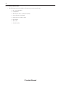
With these controls, the device offers the following therapies:
Description
Control Settings
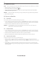
EPAP = IPAP Min < IPAP Max
The device provides CPAP as a base therapy.
The device may automatically provide pressure
support with inspiratory pressures between
IPAP Min and IPAP Max to normalize patient
ventilation during sleep disordered breathing
events. Refer to Figure 3-2.
Note: When EPAP = IPAPMin = IPAP Max, this is
equivalent to traditional CPAP therapy.
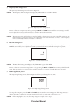
EPAP < IPAP Min < IPAP Max
The device delivers minimum pressure support
determined by the EPAP and IPAP Min controls.
The device may automatically provide additional
pressure support with inspiratory pressures
between IPAP Min and IPAP Max to normalize
patient ventilation during sleep disordered
breathing events. Figure 3-3 illustrates the
automatic adjustment of IPAP during a sleep
disorder breathing event and during normal
breathing.
Note: When EPAP < IPAP Min = IPAP Max, this is
equivalent to traditional bi-level therapy.
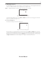
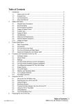
Pressure
IPAP max
EPAP = IPAP min
Time
Flow
Target Flow
Time
Figure 3-2 CPAP Therapy with Automatic Pressure Support
Provider Manual
3-3
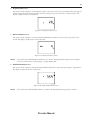
Pressure
IPAP max
IPAP min
EPAP
Time
Flow
Target Flow
Time
Figure 3-3 Bi-Level Therapy with Automatic Pressure Support
3.2.2 Back-up Breath Rate Controls
In addition to the pressure controls, the device may be configured to deliver machine-triggered breaths if the patient does not
spontaneously breathe at a determined rate. Back-up breaths are machine-triggered, machine-cycled breaths. The Rate and
Time Insp controls are used to configure back-up breaths to one of three selections.
Control Settings
Description
Back-up Rate: OFF
No back-up breaths are delivered to the patient. The initiation of each
breath is exclusively controlled by the patient. The device triggers to
IPAP in response to spontaneous inspiratory effort, and cycles to EPAP
during exhalation. Figure 3-4 illustrates the trigger and cycle concepts.
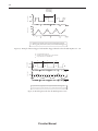
Back-up Rate: 4-30
Time Insp: .5 - 3
Back-up Rate: Auto
This selection ensures that the patient will receive a minimum number
of breaths per minute if their spontaneous breathing rate drops below the
breath rate specified by the Rate control. If the patient fails to initiate an
inspiration within the breath period determined by the control, the device
triggers a timed breath. The duration of each breath is controlled by the
Time Insp control. Figure 3-5 illustrates patient-triggered and machinetriggered breaths when the back-up rate is 4-30.
With Auto selected, the back-up rate and the time of inspiration are
automatically determined by the device. Spontaneous breaths are used
to compute an average breath period and inspiratory period. (The 2 to 3
breaths prior to central apnea may be insufficient to ventilate. Thus,
tidal volumes less than 100 ml are not counted as a breath. Timed breaths
are delivered in groups of 5 breaths. The First Timed breath has separate
timing criteria as compared to the subsequent 4 breaths.) Figure 3-6
illustrates breathing intervals when the back-up rate is Auto.
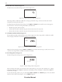
Inspiration
Trigger
Rise Time
Cycle
Expiration
IPAP
EPAP
Inspiratory Time
Figure 3-4 Triggering and Cycling when the Back-Up Rate is Off
Provider Manual
3-4
IPAP
S
EPAP
Vol (ml)
P (cm H2O)
Time Interval
Based on the
Rate Setting
S
S
T
S
S
T
S
S = Spontaneously-triggered pressure support breaths (Patient-triggered)
T = Time-triggered, pressure-limited, time-cycled breath (Machine-triggered)
Figure 3-5 Example of Patient-Triggered and Machine-Triggered Breaths when the Back-Up Rate is 4 - 30
t a = normal breathing interval
t b = breathing interval that triggers a timed breath
t c = inspiration time of a timed breath
Vol (ml)
P (cm H2O)
ta
tb
tc
IPAP
EPAP
T
S
S
S
100
S
S
T
S
S = Spontaneously triggered pressure support breaths (Patient-triggered)
T = Time-triggered, pressure-limited, time-cycled breath (Machine-triggered)
Figure 3-6 Breathing Intervals when the Back-Up Rate is Auto
Provider Manual
3-5
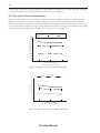
3.2.3
Ramp
The device is equipped with a linear ramp function. When activated, the ramp feature reduces the pressure and then gradually
increases (ramps) the pressure to the prescription pressure setting so patients can fall asleep more comfortably. Figure 3–7
illustrates how the ramp function works.
Airflow
Turned On
Ramp Button
Pressed
IPAP Min
Pressure
EPAP
Pressure
Minimum
Pressure
Support
Ramp Start
Pressure
0 cm H2O
Ramp Time
Minutes
Linear Ramp
* The minimum pressure support is defined
as the lesser of 2 cm H2O and the
difference between IPAP Min and EPAP
pressure settings.
Figure 3-7 The Ramp Function
3.2.4
Digital Auto-Trak™ Sensitivity
An important characteristic of the BiPAP autoSV device is its ability to recognize and compensate for unintentional leaks in
the system and to automatically adjust its trigger and cycle algorithms to maintain optimum performance in the presence
of leaks. This feature is known as Digital Auto-Trak Sensitivity. The following sections examine this function in detail by
describing the leak tolerance function and sensitivity.
3.2.4.1
Leak Tolerance
A microprocessor monitors the total flow of the patient circuit and calculates patient flow values.
A. Leak Estimation: Average and Parabolic
The device uses two leak estimation algorithms. A conservation of mass algorithm is used to compute the average leak
for a given pressure support relationship. This average leak is used when large leak variations are present in the system.
Average leak is a high estimate during EPAP pressure and a low estimate during IPAP pressure.
A better leak estimate, enabled by the digital system, is the parabolic leak algorithm. Parabolic leak is proportional to the
square of the patient pressure; therefore, the leak estimate is correlated to the changing patient pressure. Both algorithms
include unintentional circuit leak and are averaged over several breaths.
B. Patient Flow
The total circuit flow is comprised of the circuit leak and the patient flow. The calculated patient flow is the total flow
minus the circuit leak. Patient flow is a primary input into the triggering and cycling mechanisms.
3.2.4.2
Sensitivity
An essential feature of the device’s triggering function is its ability to effectively sense spontaneous breathing efforts, which
causes the ventilator to trigger to IPAP and cycle to EPAP. Because no preset sensitivity threshold can assure patient and
machine synchrony with changing breathing efforts and circuit leaks, the device continuously tracks patient breathing
patterns and automatically adjusts sensitivity thresholds to ensure optimum sensitivity as breathing patterns change or as
circuit leaks change. The algorithm used to ensure optimum sensitivity is the Volume Trigger.
Provider Manual
3-6
Volume Trigger (EPAP to IPAP)
The volume trigger is the method used to trigger IPAP during spontaneous breathing. The volume trigger threshold is 6 ml
of accumulated patient inspiratory volume. When patient effort generates inspiratory flow causing 6 ml of volume, IPAP is
triggered.
Shape Trigger (EPAP to IPAP)
The shape trigger is another method used to trigger IPAP during spontaneous breathing. This method continuously tracks
patient inspiratory and expiratory flow and adjusts the spontaneous trigger threshold for optimum sensitivity. The shape
signal appears as a shadowy image of the patient’s actual flow. The shape signal functions as a sensitivity threshold at
inspiration. When the patient’s flow rate crosses the shape signal, the unit changes pressure levels. Figure 3–8 illustrates how
the shape signal is superimposed onto the actual waveform to trigger to IPAP.
The shape signal is created by offsetting the signal from the actual patient flow by 15 LPM and delaying it for a 300 msec
period. This intentional delay causes the shape signal to be slightly behind the patient’s flow rate. A sudden change in patient
flow will cross the shape signal, causing the pressure level to change.
Figure 3-8 Shape Signal
Tracking the patient’s flow pattern with the shape signal provides a sensitive mechanism to trigger to IPAP in response to
changing breathing patterns and circuit leaks.
Spontaneous Expiratory Threshold (IPAP to EPAP)
The method used to cycle off IPAP during spontaneous breathing is called Spontaneous Expiratory Threshold (SET). The
SET rises in proportion to the inspiratory flow rate on each breath. When the SET and the actual patient flow value are equal,
the unit cycles to EPAP.
Figure 3-9 Spontaneous Expiratory Threshold
Provider Manual
3-7
Maximum IPAP Time (IPAP to EPAP)
A maximum IPAP time of 3.0 seconds acts as a safety mechanism to limit the time spent at the IPAP level during
spontaneous breathing. Once the time limit is reached, the unit automatically cycles off IPAP to the EPAP level.
Summary
The sensitivity criteria for spontaneous breathing can be summarized as follows:
Spontaneous Trigger to IPAP
A transition from EPAP to IPAP occurs when one of the following conditions is met:
•
•
Patient flow exceeds the shape signal
6 ml inspired patient volume
Cycle to EPAP
The transition from IPAP to EPAP occurs when one of the following conditions is met:
•
•
Spontaneous Expiratory Threshold (SET) is achieved
A 3.0 second maximum IPAP time has occurred (safety feature)
3.3 Access Levels
There are two levels of access:
•
Provider Mode
•
User Mode
3.3.1
Provider Mode Access Level (Setup)
The Provider mode unlocks additional parameters that are not available to the patient. This mode is accessed by completing
the following steps:
1. Plug in the device to power up the device.
2. Press the Right User button and the SILENCE button simultaneously for at least two seconds (see Figure 3-10).
SETUP appears in the top right corner of the display, and the EPAP Setting screen will display. This indicates that
you are now in Provider mode.
NOTE:
It does not matter whether you press the Right User button or the SILENCE button first.
Display
Screen
Scroll
Button
Pressure On/Off
Button
RESET
HEAT
Alarm
Reset
Button
RAMP
Heated
Humidifier
Button
NOTE:
User
Buttons
SILENCE
Ramp
Button
Figure 3-10 Control Panel
Alarm
Silence
Button
The device can be configured to remain in Provider mode by changing the Access Level Setting. See Chapter 6 for
more information.
Provider Manual
3-8
3. Navigate the screens and change the settings as described in Chapter 6.
You can display and modify the following settings in Provider mode:
• EPAP pressure
• IPAP minimum pressure
• IPAP maximum pressure
• Breath rate
• Timed inspiration
• Rise time
• Ramp length
• Ramp starting pressure
• Apnea alarm (enable/disable)
• Patient disconnect alarm (enable/disable)
• Low minute ventilation alarm (enable/disable)
• Therapy hours (erase or save)
• LED Backlight
• Access Level Setting
3.3.2
User Mode Access Level
To switch the device from Provider mode to User mode, change the Access Level Parameter from 1 to 0 in the Access Level
Setting screen. See Chapter 6 for more information.
NOTE:
If you temporarily set the device to Provider mode by pressing the Right User button and the SILENCE button,
the device will return to User mode when any of the following occurs:
•
The SILENCE button is pressed.
•
Any parameter screen times out.
•
You press the Left User button while the EPAP Setting screen is
displayed.
•
You press the Right User button while the Access Level Setting
screen is displayed.
The following settings can be modified in User mode:
•
Rise time setting
•
Ramp start pressure setting (if enabled)
•
LED backlight for control buttons (enable/disable)
•
Humidifier heat setting (from the Humidifier Setting screen)
The following is also true in User mode:
•
The Rise Time Setting screen is only displayed if the IPAP Max is greater than EPAP.
•
The Ramp Start Pressure Setting screen is only displayed if the Ramp Length setting is greater than zero.
Provider Manual
3-9
3.4 Definitions, Acronyms, and Abbreviations
The following terms appear in this manual:
•
APS—Automatic Pressure Support
•
BiPAP—Bi-level Positive Airway Pressure
•
BPM—Breaths Per Minute
•
CSA—Central Sleep Apnea
•
CPAP—Continuous Positive Airway Pressure
•
Cycle—The transition from inspiration to expiration.
•
EPAP—Expiratory Positive Airway Pressure
•
High Priority Alarm—Alarm signal indicating a condition that requires immediate attention
•
IPAP—Inspiratory Positive Airway Pressure
•
IPAP Max—The maximum IPAP setting established by the health care professional.
•
IPAP Min—The minimum IPAP setting established by the health care professional.
•
LCD—Liquid Crystal Display
•
LEAK—Measured Average Leak
•
LED—Light Emitting Diode
•
Low Minute Ventilation—A condition in which the patient is not receiving a specified volume of air on a per
minute basis.
•
Low Priority Alarm—Signal indicating an information message.
•
LPM—Liters Per Minute
•
Medium Priority Alarm—Alarm signal indicating a condition that requires operator awareness.
•
MinVent—Minute Ventilation
•
NPPV—Non-invasive Positive Pressure Ventilation
•
Operate State—The state of the BiPAP autoSV device when the device and the airflow are both on.
•
OSA—Obstructive Sleep Apnea
•
Ramp—A feature that may increase patient comfort when therapy is started. The ramp feature will reduce the
pressure and then gradually increase (ramp) the pressure to the prescription pressure setting so patients can fall asleep
more comfortably.
•
RR—Respiratory Rate
•
SET—Spontaneous Expiratory Threshold
•
Standby State—The state of the BiPAP autoSV device when it is on, but the airflow is off.
•
Ti—Inspiratory Time
•
Trigger—The transition from expiration to inspiration.
•
VTE—Exhaled Tidal Volume
Provider Manual
3-10
3.5 Symbol Key
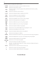
The following symbols appear on the device label:
Symbol
Meaning
Attention, consult accompanying documents
DC Power
Pressure On/Off
Type BF Applied Part
Class II (Double Insulated)
European CE Declaration of Conformity
Canadian/US Certification
Electrostatic Discharge
IPX1
Drip Proof Equipment
UL Recognized for Canada and the United States
TUV Safety Standard Compliance
No User Serviceable Parts
3.6 Service
If you need product support, call the Respironics Customer Service department at 1-724-387-4000 or 1-800-345-6443. You can
also use the following address:
Respironics
1001 Murry Ridge Lane
Murrysville, PA 15668
Visit the Respironics web site at: www.respironics.com.
Provider Manual
4-1
Chapter 4: Controls and Displays
This chapter describes the control panel and displays, the patient circuit connections, and the rear panel connections.
4.1 Controls and Displays
AC Power
Indicator (Green)
High Priority
Alarm LED (Red)
AC
Alarms
Power
DC
DC Power
Indicator (Green)
Low/Medium Priority
Alarm LED (Yellow)
Display
Screen
Scroll
Button
Pressure On/Off
Button
Alarm
Reset
Button
RESET
HEAT
RAMP
Heated
Humidifier
Button
User
Buttons
SILENCE
Alarm
Silence
Button
Ramp
Button
Figure 4-1 The Control Panel
Figure 4-1 illustrates the control panel. The control panel includes:
•
A display screen where all device settings appear
•
Control buttons
•
Alarm indicators
•
Power indicators
4.1.1
Display Screen
The display screen shows operating parameters, instructions, and messages. A backlight activates when the user buttons are
pressed, and remains on until there are no buttons pressed for one minute. Figure 4-2 shows the display screen.
ALARM PATIENT HEAT RAMP SETUP
APNEA LIGHT START CARD
s ml
LEAK
cm
MinVent VTE
H
2O
RR
BPM
ERASE HOURS
RISE TIME
IPAP IPAP EPAP
Max Min
BPM
Figure 4–2 Display Screen
Provider Manual
Ti
4-2
The information shown on the display screen is defined as follows:
ALARM
Indicates that the device requires user attention as indicated on the screen.
APNEA
Indicates that an apnea alarm has occurred.
BPM
CARD
cm H2O
Indicates that a breath rate setting is being displayed. This symbol flashes when the device is providing
timed backup breaths.
Indicates that a SmartCard is inserted and detected.
Indicates that the alphanumeric digits are displaying a pressure value.
EPAP
Indicates that an EPAP pressure setting is being displayed.
ERASE
Indicates that the user may clear the Therapy Hour Meter.
HEAT
HOURS
Indicates that the humidifier is turned on and/or its setting is displayed.
Indicates that the Therapy Hour Meter is being displayed.
IPAP
Max
Indicates that an IPAP maximum pressure setting is being displayed.
IPAP
Min
Indicates that an IPAP minimum pressure setting is being displayed.
LEAK
Indicates that the Estimated Leak Rate is being displayed.
LIGHT
Indicates that the control pad LED backlight setting is being displayed or is active.
LPM
Indicates that the value displayed is in liters per minute.
MinVent
ml
PATIENT
Indicates that the Estimated Minute Ventilation is being displayed.
Indicates that the value displayed is in milliliters.
Indicates that a Patient Disconnect alarm is active or a patient disconnect alarm setting is being displayed.
RAMP
Indicates that the Ramp function is in progress or the ramp length setting is being displayed.
RAMP
START
Indicates that the Ramp Starting Pressure is being displayed.
RISE TIME
RR
s
SETUP
Ti
VTE
Indicates that a rise time setting is being displayed.
Indicates that the Respiratory Rate (RR) is being displayed.
The small “s” on the right side of the display (above “cm H2O”) indicates that the alphanumeric digits are
displaying a time value, in seconds.
Indicates that the device is in Provider mode and not in User mode.
Indicates that an inspiratory time setting is being displayed.
Indicates that the Estimated Exhaled Tidal Volume is being displayed.
Provider Manual
4-3
4.1.2
Control Buttons
The control buttons, shown in Figure 4-3, are defined below.
Display
Screen
Scroll
Button
Pressure On/Off
Button
Alarm
Reset
Button
RESET
HEAT
RAMP
Heated
Humidifier
Button
User
Buttons
SILENCE
Alarm
Silence
Button
Ramp
Button
Figure 4–3 Control Buttons
This button starts or stops the device’s airflow. Press the button in to turn the airflow On. This puts the device
in the Operate state. When the button is in the Off position, the device is in the Standby state, any ramp in
progress is terminated, the alarms are reset (except for the System Errors alarm), and the humidifier is turned
off. The Pressure On/Off button is independent of the display screen. Figure 4–4 shows the button’s On and
Off positions.
Airflow
On
Airflow
Off
Figure 4–4 Pressure On/Off Button (on the side of the device)
HEAT
When the optional REMstar Heated Humidifier has been prescribed, this button controls the
humidifier’s output. Follow the instructions included with the humidifier. This button can also be used
to adjust the parameters shown in the provider and user menu screens.
RAMP
When the airflow is turned on, this button lowers the airflow pressure, allowing the patient to fall asleep
more easily. This button can also be used to adjust the parameters shown in the provider and user menu
screens.
Press the left and right user buttons to navigate the display screens.
SILENCE
This button temporarily silences the audible portion of an alarm. Additionally, it allows you to exit a
parameter screen.
RESET
This button acknowledges an alarm and resets the device for alarm detection.
SILENCE
Use this button to scroll through the measured monitoring parameters.
Provider Manual
4-4
4.1.3
Indicators
The alarm and power indicators, shown in Figure 4–5, are described below.
AC Power
Indicator (Green)
High Priority
Alarm LED (Red)
AC
Power
Alarms
DC
DC Power
Indicator (Green)
Low/Medium Priority
Alarm LED (Yellow)
Figure 4–5 Alarm and Power Indicators
AC Power Indicator
The green AC Power LED illuminates when the device is connected to AC power.
DC Power Indicator
The green DC Power LED illuminates when the device is connected to DC power.
High Priority Alarm
Indicator
The red High Priority Alarm LED illuminates when a high priority patient or system alarm
occurs.
Low/Medium Priority
Alarm Indicator
NOTE:
4.1.4
The yellow Low/Medium Priority Alarm LED illuminates when a medium or low priority patient or
system alarm occurs.
All LED indicators temporarily turn on when the device is first plugged in.
Audible Alarms and Indicators
Audible alarms and indicators, discussed in detail in Chapter 7, can be heard in the following situations:
•
Power Failure – An alarm sounds when power is lost.
•
High priority system or patient alarms – An alarm sounds several times at intervals for a high priority alarm.
•
Medium priority system alarms – An alarm sounds three times for a medium priority alarm.
•
Low priority system alarms – An alarm sounds twice for a low priority alarm.
•
Provider mode – An alarm sounds twice when the provider mode is accessed using the key sequence described in
Section 3.3.1.
•
SmartCard activity – An alarm sounds once when the SmartCard is inserted or removed.
•
Power on – An alarm sounds once when the device’s power cord is connected.
•
Confirmation – An alarm sounds once when the airflow is turned on, when the humidifier parameter screen is
entered, and when the humidifier is turned on.
4.2 Navigating the Screens
Note the following when navigating the Provider or User mode screens:
•
The Left and Right User buttons allow you to go to the previous setting or the next setting, respectively.
•
The HEAT and RAMP buttons operate as up and down buttons to adjust the settings. Pressing and holding the
HEAT or RAMP buttons down for at least 2 seconds will change the settings at a faster rate.
•
The SILENCE button allows you to exit a Provider or User mode screen.
•
The small circular Scroll button ( ) (located next to the RESET button) allows you to view measured parameters
from the Monitoring screen. See Chapter 6 for more information.
•
The alphanumeric digits and symbols flash to indicate setting adjustment.
SILENCE
Provider Manual
4-5
4.2.1
LED Backlight for Buttons
The SILENCE, RESET, RAMP, and HEAT buttons can be lit by an LED backlight. The LED backlight is on when
the device is in the Standby state or when the System Self Test Screen is displayed. When the device is in the Operate state,
the LED backlight is lit according to the setting in the LED backlight screen. The LED backlight may flash to indicate an
alarm condition as described in Chapter 7.
Control Panel Inactivity
Some screens have timeout periods. The screen’s timer starts when the screen is initially displayed, and is restarted whenever a
button is pressed. When a screen times out, the LCD backlight is turned off and the Monitoring/Standby screen is displayed.
The LCD backlight turns back on when a button is pressed again.
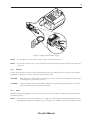
4.3 Patient Circuit Connection
The patient circuit is connected to the breathing circuit connection shown in Figure 4–6. The breathing circuit connection
accepts a bacteria filter or a tubing connector for reusable or disposable tubing.
Breathing Circuit Connection
Figure 4–6 Breathing Circuit Connection
4.4 Rear Panel
Figure 4–7 shows the rear panel.
Communications
Connector Port
Power Inlets
Cord Retainer
SmartCard
Slot
(Connector)
Cord Retainer
Filter Cap
Figure 4–7 Rear Panel
NOTE:
The SmartCard connector (SmartCard slot) is located on the side of the device.
WARNING:
In order to ensure proper protection against electric shock, only communications accessories with an IEC
60601-1 approved power supply may be connected through the SleepLink interface. All IEC 950 devices
must only be connected to the 7-pin connector with the Respironics Isolation cable (Part Number 1012865).
Provider Manual
4-6
The rear panel contains the following:
•
A communications connector that accepts the Respironics Communications Cable for computer and external
communications or a remote alarm, when available. (Use only with an IEC 60950 approved computer.)
•
Two power inlets: one for connecting the external AC power supply and another for connecting the DC power
adapter.
•
The filter cap that is removed to inspect the inlet air filters.
•
Two cord retainers that provide strain relief for the power cord.
4.5 SmartCard
The device is delivered with the SmartCard installed. The SmartCard records the following data:
•
Date
•
Time
•
Leak
•
Pressure
•
Tidal volume
•
Peak flow
•
Apnea events
•
Hypopnea events
•
Duration of each use (minimum storage capacity is six months)
When capacity is reached, the oldest data is overwritten. Using the Respironics SmartCard reader/writer and the Encore
Pro software, you can download and view the usage data. Follow the instructions included with the Encore Pro software to
download the data.
Figure 4–8 Encore Pro SmartCard
NOTE:
If the card is not installed, the device usage will not be recorded. When a SmartCard is installed, CARD appears
in the upper right corner of the display screen.
Provider Manual
5-1
Chapter 5: Setup
5.1 Preparing the Device
This section contains information on:
•
Installing the air filters.
•
Assembling the patient circuit.
•
Supplying power to the device.
•
Startup.
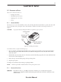
5.1.1
Installing the Air Filters
The device uses one or two removable filters at the air inlet. The disposable white ultra-fine filter is optional. You must install
the gray foam filter before operating the device. The foam filter is washable and reusable. For cleaning instructions, see
Chapter 8.
CAUTION:
A properly installed, undamaged foam filter is required for proper operation.
Communication
Port
Reusable Gray
Foam Filter
(required)
Filter
Cap
Disposable Ultra-fine
Filter (optional)
Figure 5-1 Installing the Air Filters
To install the air filters, complete the following steps:
1. If you are using the optional white ultra-fine filter, place it against the gray foam filter so the soft side of the ultra-fine
filter touches the gray foam filter. When the filters are installed, the hard plastic side of the white filter will touch the
inside of the device.
2. Slide the filters into the air inlet at the rear of the device (with the white filter going in first, if it’s used). Push them down
into the recess as shown in Figure 5-1.
3. Position the cap so that the small opening on the cap is facing down.
4. Snap the cap into place.
See Chapter 8 for information about cleaning or replacing the filters.
NOTE:
5.1.2
The filter cap should be installed with the air inlet opening at the bottom.
Assembling the Patient Circuit
WARNING:
The exhalation device (e.g., the Whisper Swivel® II) or exhalation port (on masks with an integrated
exhalation port) is designed to exhaust CO2 from the patient circuit. Do not block or seal the ports on the
exhalation device.
Provider Manual
5-2
1. Assemble the patient circuit according to the configurations presented in Chapter 10.
2. If required, connect a bacteria filter to the breathing circuit connection (shown in Figure 5-2), and connect the patient
tubing to the outlet of the bacteria filter.
•
If the bacteria filter is not required, connect the patient tubing directly to the breathing circuit connection.
•
If a humidifier is to be used, connect the inlet to the bacteria filter outlet or to the breathing circuit connection.
A completed assembly (without humidifier) appears in Figure 5-2.
Patient Interface
Exhalation Port
Circuit
Tubing
Bacteria
Filter
(Optional)
Breathing
Circuit
Connection
Figure 5-2 An Example of a Typical Circuit
5.1.3
Supplying Power to the Device
WARNING:
The BiPAP autoSV device can operate on AC or DC power. The DC power option is not intended as a
battery backup during use of AC power.
CAUTION:
When DC power is obtained from a vehicle battery, the device should not be used while the vehicle’s engine
is running. Damage to the device or the vehicle may occur.
WARNING:
Route the wires to avoid tripping.
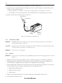
5.1.3.1 AC Operation
WARNING:
For proper use, the external AC power supply must be placed feet down, in the upright position, as shown in
Figure 5–3.
1. Plug the pronged end of the AC power supply’s cord into an electrical outlet that is not controlled by a wall switch.
2. The external AC power supply features a cord retainer to provide strain relief for the AC power cord. Wrap the cord
around the AC power supply’s cord retainer, using the wire tie supplied with your power supply.
3. Leaving a small amount of slack in the cord, connect the cord on the other side of the power supply to one of the power
inlets on the device. The power cord has a locking connector. To properly plug the cord in:
a. Pull the locking mechanism back.
b. Push the connector into place.
c. Release the lock.
4. Wrap the cord around the device’s power cord retainer, which provides strain relief for the power cord.
5. Ensure that all connections are secure.
Provider Manual
5-3
Figure 5-3 Using the External Power Supply
NOTE:
You can plug the cord into either of the power inlets on the back of the device.
NOTE:
If you need to disconnect the power cord from the device, slide the locking connector back and then remove the
power cord.
5.1.3.2 DC Operation
You can operate the device on DC power by using the Respironics DC power adapter accessory. See the DC power adapter
instructions for information on how to operate the device using DC power.
CAUTION:
When DC power is obtained from a vehicle battery, the device should not be used while the vehicle’s engine
is running. Damage to the vehicle may occur.
CAUTION:
Only use the Respironics DC power adapter available from your health care professional. Use of any other
system may cause damage to the device or the vehicle.
5.1.4
Startup
When the power cord is plugged into an AC or DC power source, the device sounds a confirmation alarm, and the control
panel buttons light up.
NOTE:
If the alarm does not sound or the buttons do not light up, the device requires servicing. Additionally, if any of
the alphanumeric digits shown in Figure 5–4 do not display on the Self Test screen, the device requires servicing.
Provider Manual
5-4
1. The first screen to appear is the Self Test screen:
ALARM PATIENT HEAT RAMP SETUP
APNEA LIGHT START CARD
s ml
LEAK
cm
MinVent VTE
H2 O
RR
BPM
ERASE
HOURS
RISE TIME
IPAP IPAP EPAP
Max Min
Ti
BPM
Figure 5-4 Self Test Screen
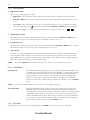
2. The next screen displays the software version:
Figure 5-5 Software Version Screen
NOTE:
The version number shown in Figure 5-5 is an example, your device may have a different software version
installed.
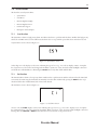
3. The Blower Hours Screen then appears, which displays the Blower Hours Time Meter:
HOURS
Figure 5-6 Blower Hours Screen
NOTE:
With the exception of the
button, buttons on the control panel are inactive during these first three screens.
NOTE:
Each of the first three screens appears for approximately 1-3 seconds.
4. The next screen to appear is the Standby screen:
PATIENT HEAT
APNEA LIGHT
HOURS
Figure 5-7 Standby Screen
Provider Manual
CARD
5-5
The Standby screen appears when the device is in the Standby state. Pressing the
Operate state. The Monitoring screen then appears:
button in puts the device in the
PATIENT HEAT RAMP
APNEA LIGHT
CARD
cm
H2O
IPAP IPAP EPAP
Max Min
BPM
Ti
Figure 5-8 Monitoring Screen
Both the Monitoring and the Standby screens display PATIENT, APNEA, LIGHT, and HEAT if these features are
enabled. Likewise, CARD displays if a SmartCard is inserted, and SETUP displays if the access level is set to Provider
mode. The Monitoring screen displays RAMP, if ramp is enabled and the RAMP button has been pressed. If fixed timed
backup rate is prescribed, BPM and Ti will be displayed if the health care professional set the breath rate between 4-30
BPM. For more information about the Monitoring Screen and parameters that you can view from here, see Chapter 6.
5. When in the Standby or Monitoring screens, you can modify the Humidifier setting by pressing and holding the HEAT
button until the screen below appears (Figure 5–9).
HEAT
SETUP
Figure 5–9 Humidifier Setting Screen
You can increase or decrease the humidifier setting from 1 to 5 in increments of 1. The setting changes immediately as you adjust it.
5.1.5
Entering Provider Mode
There are two ways to select Provider mode access.
1. To temporarily enter Provider mode when the device is in User mode, hold down the Right User button and SILENCE
button simultaneously for at least 2 seconds. SETUP appears in the upper right corner of the screen, and the EPAP
setting screen displays.
2. Once the device is in Provider mode, you can configure the device to remain in Provider mode via the Access Level
screen, as described in Section 6.1.2.
IMPORTANT: Prescribed therapy settings can only be set in Provider mode. To prevent patients from tampering with the
settings, do not allow them to access Provider mode.
5.1.6
Performance Verification
After powering up the device and entering Provider mode, perform the operational verification as described in Chapter 11.
5.2 Setting up the Device
Before using the device on a patient, set the prescription:
1. To change the settings, see Chapter 6.
2. To set the necessary alarms, see Chapter 7.
3. Verify that the device is not left in Provider mode.
Provider Manual
5-6
5.3 Connecting the Patient
NOTE:
Before connecting the patient to the device, check the integrity of the patient circuit, exhalation port, and alarms.
1. Make sure the device is in User mode. (See Chapter 6.)
2. Turn the device’s airflow on by pressing in the
button.
3. If oxygen is being used, turn on the oxygen flow. Make sure you place the Respironics Pressure Valve (Part Number
302418) in-line with the patient circuit.
WARNING:
Always turn the airflow on before turning on the oxygen, and always turn the oxygen off before turning off the airflow.
4. Place the mask on the patient.
5.4 Setting up the SmartCard
5.4.1
Downloading Data
You can download data from the SmartCard by following the steps below:
1. Connect a Respironics SmartCard reader/writer directly to an IEC60950 Windows-compatible computer following the
instructions included with the reader/writer. Remove the SmartCard from the device and insert it into the reader/writer.
2. Follow the instructions included with your Encore Pro software to download the data.
WARNING:
5.4.2
Any IEC 60950 device must be connected through the 7-pin mini-din connector with a Respironicssupplied isolation cable (Part Number 1012865).
Programming a SmartCard
1. Connect a Respironics SmartCard reader/writer directly to an IEC60950 Windows-compatible computer following the
instructions included with the reader/writer. Remove the SmartCard from the device and insert it into the reader/writer.
2. Follow the instructions included with your Encore Pro software to program the SmartCard.
3. Remove the SmartCard from the reader/writer. If desired, write the patient’s name on the front of the card.
5.4.3
Changing Settings Using a SmartCard
To change the settings in the device using a programmed SmartCard:
1. Make sure the device is plugged in. Insert the programmed SmartCard into the slot on the right side of the device
(symbol side facing up). When the Monitoring or Standby screen displays CARD, this indicates that the card is inserted
correctly.
2. Turn the airflow on to verify the new prescription setting. The card can now be removed or you can leave the card in
the device to record device usage. Once the prescription settings have been transferred to the device, they will be deleted
from the SmartCard.
Provider Manual
6-1
Chapter 6: Changing Settings
This chapter describes the settings that can be changed when the BiPAP autoSV device is in the Provider and User modes.
6.1 Changing Settings in Provider Mode
Accessing the Provider mode setup level unlocks additional settings that cannot be changed while in User mode. When
in Provider mode, SETUP appears in the top right corner of the display. To temporarily access the Provider mode while
the device is in User mode, simultaneously press the Right User button and the SILENCE button, and hold for at least 2
seconds.
NOTE:
It does not matter whether you press the Right User button or the SILENCE button first.
An audible indicator sounds when you have successfully accessed the Provider mode. To exit Provider Mode, press the
SILENCE button.
6.1.1
Navigating Screens in Provider Mode Figure 6–1 shows how to navigate the Provider mode screens using the Left and Right User keys. The parameter symbol and
setting will flash.
NOTE:
When changing any setting in the Provider mode (except for the EPAP, IPAP Min, IPAP Max, and Ramp Start
Pressure settings), once a maximum setting is reached, it will roll over back to the minimum setting, and likewise,
once a minimum setting is reached, it will roll over back to the maximum setting for that parameter.
For example, the minimum Humidifier setting is 1 and the maximum is 5. Once the Humidifier setting is
increased to 5, if increased again, it will roll over to 1. Or, once the Humidifier setting is decreased to 1, if
decreased again, it will roll over to 5.
EPAP Setting Screen
SETUP
cm
H2O
Right User
Button
Left User
Button
EPAP
Right User
Button
RAMP SETUP
START
Left User
Button
IPAP Min Setting Screen
cm
H2O
SETUP
cm
H2O
Right User
Button
Left User
Button
IPAP
Min
Right User
Button
SETUP
APNEA
Left User
Button
IPAP Max Setting Screen
Ramp Start Pressure
Setting Screen
Only displayed if the Ramp Length
setting is greater than zero.
Apnea Alarm Setting Screen
s
SETUP
cm
H2O
Right User
Button
Left User
Button
IPAP
Max
PATIENT
Right User
Button
SETUP
s
Left User
Button
Breath Rate Setting Screen
Patient Disconnect Alarm
Setting Screen
SETUP
Only displayed if IPAP Max is
greater than EPAP.
BPM
Left User
Button
Right User
Button
BPM
Right User
Button
Left User
Button
Inspiratory Time
Setting Screen
Low Minute Ventilation Alarm
Setting Screen
SETUP
MinVent
LPM
SETUP
s
Left User
Button
Right User
Button
Only displayed if Breath Rate
is not OFF or AUTO.
Ti
Right User
Button
SETUP
Left User
Button
Rise Time Setting Screen
Reset Therapy Meter
Setting Screen
ERASE HOURS
SETUP
Only displayed if IPAP Max is
greater than EPAP.
Right User
Button
RISE TIME
Left User
Button
LIGHT
Right User
Button
Ramp Length Setting Screen
SETUP
Left User
Button
LED Backlight
Setting Screen
RAMP SETUP
Right User
Button
Left User
Button
SETUP
Right User
Button
Left User
Button
Access Level
Setting Screen
Figure 6–1 Navigating the Provider Mode Screens
Provider Manual
6-2
6.1.2
Changing Settings in Provider Mode
From each of these screens, press the Right User button to access the next one. Likewise, press the Left User button to access
the previous screen.
1. EPAP Setting Screen
The EPAP Setting screen is shown in Figure 6–2.
SETUP
cm
H2O
EPAP
Figure 6–2 EPAP Setting Screen
Increase or decrease the EPAP pressure by pressing the HEAT and RAMP buttons until the correct pressure appears. You
can adjust the pressure from 4 to 25 cm H2O in 1 cm H2O increments.
WARNING:
High EPAP pressures can cause the patient discomfort. Carefully evaluate the patient if you set the EPAP
level above 15 cm H2O.
NOTE:
If the EPAP is set to less than the ramp start pressure, the ramp start pressure automatically sets to the EPAP.
NOTE:
If EPAP is greater than IPAP Min, then IPAP Min automatically sets to EPAP.
2. IPAP Min Setting Screen
The IPAP Minimum Setting screen is shown in Figure 6–3.
SETUP
cm
H2O
IPAP
Min
Figure 6–3 IPAP Minimum Setting Screen
Increase or decrease the IPAP minimum pressure setting by pressing the HEAT and RAMP buttons until the correct
pressure appears. You can adjust the IPAP minimum setting from 4.0 cm to 30.0 cm in 1 cm H2O increments.
NOTE:
The IPAP Min value must be equal to or greater than the EPAP value.
NOTE:
If the IPAP Min Setting is set greater than IPAP Max setting, the IPAP Max automatically sets to IPAP Min.
Provider Manual
6-3
3. IPAP Max Setting Screen
The IPAP Maximum Setting screen is shown in Figure 6–4.
SETUP
cm
H2O
IPAP
Max
Figure 6–4 IPAP Maximum Setting Screen
Increase or decrease the IPAP maximum pressure setting by pressing the HEAT and RAMP buttons until the correct
pressure appears. You can adjust the IPAP maximum setting from 4.0 cm to 30.0 cm in 1 cm H2O increments.
NOTE:
The IPAP Max value must be equal to or greater than the IPAP Min value.
4. Breath Rate Setting Screen
The Breath Rate Setting screen is shown in Figure 6–5.
NOTE:
The Breath Rate Setting screen displays only if IPAP Max is greater than EPAP.
SETUP
BPM
BPM
Figure 6–5 Breath Rate Setting Screen
Increase or decrease the breath rate by pressing the HEAT and RAMP buttons until the correct setting appears. You can
adjust the breath rate from 0 to 30 in 1 BPM increments.
Provider Manual
6-4
5. Inspiratory Time Setting Screen
The Inspiratory Time Setting screen is shown in Figure 6–6.
NOTE:
The Inspiratory Time Setting screen displays only if Breath Rate is not OFF or AUTO.
SETUP
s
Ti
Figure 6–6 Inspiratory Time Setting Screen
Increase or decrease the inspiratory time by pressing the HEAT and RAMP buttons until the correct setting is reached.
You can adjust the inspiratory time from 0.5 to 3 seconds in 0.1 second increments.
NOTE:
The inspiratory time and breath rate controls are linked so the inspiratory time never exceeds the expiratory time.
If the breath rate or inspiratory time are set to values that would cause the I:E ratio to exceed 1:1, the inspiratory
time is automatically reduced to maintain a 1:1 I:E ratio.
6. Rise Time Setting Screen
The Rise Time Setting screen is shown in Figure 6–7. Rise time is the time it takes for the device to change from EPAP to
IPAP. This screen allows you to adjust the rise time so you can find the most comfortable setting for the patient.
SETUP
RISE TIME
Figure 6–7 Rise Time Setting Screen
NOTE:
The Rise Time Setting screen displays only if IPAP Max is greater than EPAP.
Increase or decrease the rise time setting from 1 to 6 by pressing the HEAT and RAMP buttons until you find the right
setting. The rise time of 1 to 6 corresponds to tenths of a second (e.g., a setting of 4 equals 0.4 second rise time).
7. Ramp Length Setting Screen
The Ramp Length Setting screen, shown in Figure 6–8, allows you to change the ramp time.
RAMP SETUP
Figure 6–8 Ramp Length Setting Screen
To change the ramp time, press the HEAT and RAMP buttons until the correct time appears. The setting increases or
decreases from 0 to 45 minutes in 5 minute increments. If you do not want ramp, set the time to zero.
NOTE:
If the ramp length is set to zero, the ramp settings are complete. Go to step 9.
Provider Manual
6-5
8. Ramp Start Pressure Setting Screen
The Ramp Start Pressure Setting screen is shown in Figure 6–9.
NOTE:
This screen displays only if the ramp length setting is greaterr than 0.
RAMP SETUP
START
cm
H2O
Figure 6–9 Ramp Start Pressure Setting Screen
To change the ramp starting pressure, press the HEAT and RAMP buttons until the correct pressure appears. The setting
increases or decreases in 1.0 cm H2O increments. The user can adjust the setting from 4 cm H2O to the current EPAP
pressure setting.
9. Apnea Alarm Setting Screen
The Apnea Alarm Setting screen is shown in Figure 6–10. This setting enables or disables the audible alert (a beeping
sound) when an apnea is detected.
APNEA
SETUP
s
Figure 6–10 Apnea Alarm Setting Screen
Change the apnea alarm setting by pressing the HEAT and RAMP buttons until the desired setting is reached. You can
increase or decrease the time from 0 to 40 seconds in 10 second increments.
•
0 disables the apnea alarm.
•
10 means that the alarm sounds if the time between spontaneous breaths exceeds 10 seconds.
•
20 means that the alarm sounds if the time between spontaneous breaths exceeds 20 seconds.
•
30 means that the alarm sounds if the time between spontaneous breaths exceeds 30 seconds.
•
40 means that the alarm sounds if the time between spontaneous breaths exceeds 40 seconds.
Provider Manual
6-6
10. Patient Disconnect Alarm Setting Screen
The Patient Disconnect Alarm Setting screen is shown in Figure 6–11.
PATIENT
SETUP
s
Figure 6–11 Patient Disconnect Alarm Setting Screen
This setting enables or disables the audible alert (a beeping sound) when a large, continuous air leak (such as mask
removal) has been detected in the circuit.
To change the patient disconnect alarm setting, press the HEAT and RAMP buttons until the correct setting appears.
You can increase or decrease the setting between 0, 15, and 60 seconds.
•
0 disables the patient disconnect alarm.
•
15 means that the alarm sounds after the patient has been disconnected for 15 seconds.
•
60 means that the alarm sounds after the patient has been disconnected for one minute.
11. Low Minute Ventilation Alarm Setting Screen
The Low Minute Ventilation Alarm Setting screen is shown in Figure 6–12. This setting enables or disables the audible
alert (a beeping sound) when a low minute ventilation event is detected.
SETUP
MinVent
LPM
Figure 6–12 Low Minute Ventilation Alarm Setting Screen
Change the alarm setting by pressing the HEAT and RAMP buttons until the desired setting is reached. You can increase
or decrease the setting from 0 to 99 LPM in increments of 1 LPM.
12. Reset Therapy Meter Setting Screen
The Reset Therapy Meter Setting screen is shown in Figure 6–13.
SETUP
ERASE HOURS
Figure 6–13 Reset Therapy Meter Setting Screen
This screen displays the number of hours that the device delivered therapy to the patient. The decimal point (.) displays
if the therapy time is less than 2000 hours. Otherwise, the decimal point does not display so values between 2000 and
19999 hours can display.
To erase the totals and go back to zero, press and hold the HEAT or RAMP button. ERASE displays on the screen. Hold
the button down until the time changes to zero and ERASE disappears.
Provider Manual
6-7
13. LED Backlight Setting Screen
The LED Backlight Setting screen is shown in Figure 6–14. This setting allows you to have the lights behind the buttons
turned on or off while the airflow is turned on and the device is in the Operate state.
NOTE:
The lights will always be on when the airflow is off and the device is in Standby.
LIGHT
SETUP
Figure 6–14 LED Backlight Setting Screen
To change the LED backlight setting, press the HEAT or RAMP button until the correct setting appears. 1 means the
lights are on, while 0 means the lights are off.
14. Access Level Setting Screen
The Access Level Setting screen is shown in Figure 6–15.
SETUP
Figure 6–15 Access Level Setting Screen
This screen allows you to select Provider mode or User mode access. Press the HEAT and RAMP buttons to select the
appropriate access level. 0 indicates that the device is in User mode, and 1 indicates that the device is in Provider mode.
This is the last screen in the Provider mode. Press the SILENCE button to exit the settings menu or continue pressing
the Right and Left User buttons as shown in Figure 6–1 to navigate to other Provider mode screens.
Provider Manual
6-8
6.2 Monitoring Measured Parameters You can view additional measured parameters from the Monitoring screen by pressing the small circular Scroll button located
near the RESET button. Figure 6–16 shows how to navigate the measured parameters screens.
NOTE:
You can also view these screens from the Standby screen, but when you do so, each of these screens displays a
value of zero because the device is not delivering therapy.
Leak Screen
LEAK
Scroll
Button
Respiratory Rate Screen
Scroll
Button
Minute Ventilation Screen
Scroll
Button
Exhaled Tidal Volume Screen
Scroll
Button
Figure 6–16 Measured Parameter Screen Navigation
To return to the Monitoring or Standby Screen from these Measured Parameter screens, press the SILENCE button.
NOTE:
The user also has access to these screens.
1. Leak Screen
This screen is shown in Figure 6–17. The Estimated Leak is the average leak value for the last six breaths. The display is
updated at the end of each breath.
LEAK
Figure 6–17 Leak Screen
Provider Manual
6-9
2. Respiratory Rate Screen
This screen is shown in Figure 6–18. The Respiratory Rate is the average of the previous six breaths. If the mode supports
machine-triggered breaths, this display will be the total breathing rate (spontaneous breaths + machine breaths). The
display is updated at the end of each breath.
Figure 6–18 Respiratory Rate Screen
3. Minute Ventilation Screen
This screen is shown in Figure 6–19. The estimated Exhaled Minute Ventilation is based on the average of the last six
breaths. The display is updated at the end of each breath.
Figure 6–19 Minute Ventilation Screen
NOTE:
The value shown for Exhaled Minute Ventilation is an estimate. The display flashes during transient conditions
such as low tidal volumes, erratic breathing, or rapidly changing leak.
4. Exhaled Tidal Volume Screen
This screen is shown in Figure 6–20. The estimated Exhaled Tidal Volume is obtained by the integration of patient flow.
The display is updated at the end of each breath.
Figure 6–20 Exhaled Tidal Volume Screen
NOTE:
The value shown for Exhaled Tidal Volume is an estimate. The display flashes during transient conditions.
Provider Manual
6-10
6.3 Changing Settings in User Mode
With the device in User mode, the patient is restricted to viewing the following:
•
Measured pressure
•
Backlight settings
•
Humidifier, SmartCard, and ramp status
•
Patient alarms
•
Measured Parameters (Leak, Respiratory Rate, Minute Ventilation,
Exhaled Tidal Volume)
The patient can change the following settings in User mode:
•
Humidifier (heat)
•
Rise time
•
Ramp start pressure
•
LED backlight
NOTE:
These settings can also be changed when the device is in Provider mode. Detailed instructions for changing these
settings are described in Section 6.1.
The figure below shows how to navigate the User mode screens using the Left and Right User buttons. These screens time out
after 60 seconds of inactivity.
Rise Time Setting Screen
Only displayed if the rise time feature
is prescribed.
RISE TIME
Right User
Button
Left User
Button
RAMP
START
Ramp Start Pressure Setting Screen
cm
H2O
Only displayed if the ramp feature
is prescribed.
Right User
Button
Left User
Button
LIGHT
LED Backlight Setting Screen
Figure 6–21 Navigating the User Mode Screens
NOTE:
When in User mode, SETUP does not appear in the top right corner of the display.
Provider Manual
7-1
Chapter 7: Alarms
This chapter describes the device alarms, how to set them, and what corrective actions to take for the alarm conditions.
7.1 Alarm Introduction
The device provides three alarm levels: high, medium, and low priority.
High Priority
These alarms require immediate operator response. The alarm signal consists of a red LED
and a high priority sound. The display has ALARM at the top of the screen.
Medium Priority
These alarms require prompt operator response. The alarm signal consists of a yellow LED
and a medium priority sound. The display has ALARM at the top of the screen.
Low Priority
These alarms require operator awareness. The alarm signal consists of a yellow LED and a low
priority sound. The display has ALARM at the top of the screen.
Some audible alarms are self-cancellable. This means that the alarm sound stops when the cause of the alarm is corrected. See
section 7.3 for detailed descriptions of the alarm LEDs and sounds.
Figure 7–1 identifies the alarm LEDs and buttons on the control panel.
High Priority
Alarm LED (Red)
AC
Power
Alarms
DC
Low/Medium Priority
Alarm LED (Yellow)
Alarm
Reset
Button
RESET
HEAT
RAMP
SILENCE
Alarm
Silence
Button
Figure 7–1 Alarm LEDs and Buttons
7.1.1
Overview of Alarm Behavior
Alarm conditions are signalled in three ways: a sound, an LED, and a display message. Each signal type behaves differently
depending on the type of alarm.
Provider Manual
7-2
7.1.1.1 Alarm Sounds Behavior
1. High Priority Sounds
There are two possible high priority sounds:
•
High Priority – The sound repeats a pattern of three beeps followed by a pause and then two more beeps until the
SILENCE or RESET button is pressed. The silence period is one minute. This pattern is indicated in Section 7.5 as
• ••
•
••
Loss of Power – The sound repeats a pattern of a two-second beep followed by a two-second pause periodically
without user intervention. The
button silences this alarm. The SILENCE and RESET buttons and the LED
control panel backlight do not apply to this alarm. This pattern is indicated in Section 7.5 as
2. Medium Priority Sound
The medium priority sound repeats a pattern of three beeps every 20 seconds until the SILENCE or RESET button is
pressed. The silence period is one minute. This pattern is indicated in Section 7.5 as
•••
3. Low Priority Sound
The low priority sound repeats a pattern of two beeps every 30 seconds until the SILENCE or RESET button is pressed.
The audible alarm will not reoccur. This pattern is indicated in Section 7.5 as
••
4. Silence Period
The silence period for all applicable alarms is one minute. When the alarm sound is silenced, a flashing LED becomes
continuous. If the alarm condition is not corrected by the end of the silence period, the alarm sound is repeated; the
LED will flash again. If a new high or medium priority alarm condition occurs during this time, the appropriate LED
flashes. New low priority alarms do not cause the LED to flash.
NOTE:
Pressing the SILENCE button while the silence period is active does not restart the silence period.
7.1.1.2 Alarm LED Behavior
Red Alarm LED
NOTE:
The red alarm LED indicates high priority system and patient alarms. The LED flashes when
a new high priority alarm is detected. It changes from flashing to continuous when the alarm
sound is silenced or the alarm condition is corrected. The LED resumes flashing when the
silence period expires or if a new alarm occurs. The LED turns off when all high priority
alarms with an automatic reset method end and there are no high priority alarms with a
manual reset method active. Additionally, the red LED turns off when you press the RESET
button.
A continuous red LED indicates a loss of power or a silenced high priority alarm.
Yellow Alarm LED
The yellow alarm LED indicates medium or low priority system and power alarms. The
LED flashes when a new medium priority alarm is detected. It changes from flashing to
continuous when the alarm sound is silenced or if the alarm condition is corrected. The LED
resumes flashing when the silence period expires or if a new alarm occurs. The LED turns
off when all medium and low priority alarms with an automatic reset method end and there
are no medium or low priority alarms with a manual reset method active. Additionally, the
yellow alarm LED turns off when you press the RESET button.
7.1.1.3 Display Behavior
For high, medium, and low priority alarms, the display shows ALARM and the error code or name of the alarm.
Provider Manual
7-3
7.2 System Alarms
The device has several system alarms:
•
System Errors
•
Card Errors
•
Pressure Regulation High
•
Pressure Regulation Low
•
Low Pressure Support
•
Prescription Card Complete
7.2.1
System Error Alarm
The System Error alarm is a high priority alarm. It indicates that there is a problem with the device. Unlike other high priority
alarms, the red LED cannot be turned off because the alarm does not stop until the power shuts down and is then restored.
A System Error screen is shown in Figure 7–2.
ALARM
Figure 7–2 System Error Screen
A three digit error code displays on the screen, indicating the type of error (e.g., error code 57 displays as E57). A complete
list of system error codes can be found in Appendix A. When a system error occurs, the device’s LCD backlight is turned on
and the blower and humidifier are off. Pressing the RESET button only shuts off the audible alarm.
7.2.2
Card Error Alarm
The SmartCard Error alarm is a low priority alarm. It indicates that a problem exists with the card inserted in the SmartCard
connectivity slot. Removing the SmartCard automatically resets this alarm. Additionally, pressing the RESET button stops
the alarm until another invalid SmartCard is inserted and detected.
The Card Error screen is shown in Figure 7–3.
ALARM
CARD
Figure 7–3 Card Error Screen
An error code and CARD displays on the screen, indicating the type of error (e.g., error code 1 displays as C1). A complete
list of SmartCard error codes can be found in Appendix A. When a card error occurs, the device’s LCD backlight is turned on.
Pressing either the SILENCE or RESET button exits this screen and returns to the previous screen.
Provider Manual
7-4
7.2.3
Pressure Regulation High Alarm
The Pressure Regulation High alarm is a high priority alarm. It indicates that the outlet pressure is greater than 5 cm H2O
above the current IPAP setting. This alarm does not reset automatically. Press the RESET button to manually reset this alarm.
ALARM
cm
H2O
Figure 7–4 Screen for Pressure Regulation High Alarm,
Pressure Regulation Low Alarm, and Low Pressure Support Alarm
NOTE:
The Pressure Regulation High Alarm, Pressure Regulation Low Alarm, and Low Pressure Support Alarm all
display the same screen.
When this screen displays a Pressure Regulation High alarm, the cm H2O and ALARM flash and the LCD backlight is
turned on. Pressing either the SILENCE or RESET button exits this screen and returns to the previous screen.
7.2.4
Pressure Regulation Low Alarm
The Pressure Regulation Low alarm is a high priority alarm that indicates when the patient is not receiving adequate pressure
therapy (the outlet pressure is 5 cm H2O below the current IPAP setting). This alarm does not reset automatically. Press the
RESET button to manually reset this alarm.
Figure 7–4 shows the screen that appears when a Pressure Regulation Low alarm occurs. This screen is identical to the Pressure
Regulation High alarm or Low Pressure Support alarm screens. When this screen displays a Pressure Regulation Low alarm,
the cm H2O and ALARM flash and the LCD backlight is turned on. Pressing either the SILENCE or RESET button exits
this screen and returns to the previous screen.
7.2.5
Low Pressure Support Alarm
The Low Pressure Support alarm is a high priority alarm that indicates that a low pressure support condition has been
detected for 60 seconds. This alarm does not reset automatically. Press the RESET button to manually reset this alarm.
Figure 7–4 shows the screen that appears when a Low Pressure Support alarm occurs. This screen is identical to the Pressure
Regulation High (or Low) alarm screens. The cm H2O and ALARM flash and the LCD backlight is turned on. Pressing
either the SILENCE or RESET button exits this screen and returns to the previous screen.
7.2.6
Prescription Complete Alarm
Figure 7–5 shows the screen that appears when a Prescription Complete alarm occurs.
ALARM
CARD
cm
H2O
Figure 7–5 Prescription Complete Alarm Screen
If a prescription-only SmartCard is inserted in the device and is successfully written to the device, CARD, cm H2O and
ALARM flash and a low priority audible alert sounds. Press the RESET button to reset the alarm.
Remove the SmartCard from the device to exit this screen and return to the previous screen.
Provider Manual
7-5
7.3 Patient Alarms
The device has the following patient alarms:
•
Apnea
•
Patient Disconnect
•
Low Minute Ventilation
7.3.1
Apnea Alarm
Figure 7–6 shows the alarm screen.
ALARM
APNEA
Figure 7–6 Apnea Alarm Screen
The Apnea alarm is a high priority alarm that detects the cessation of spontaneous breathing. It occurs when the time between
spontaneous breaths exceeds the Apnea alarm time setting (10, 20, 30, or 40 seconds). See Chapter 6 for information on how
to set the Apnea alarm time.
When an apnea alarm occurs, APNEA and ALARM flash on the display and the LCD backlight is turned on.
NOTE:
A setting of zero disables the Apnea alarm.
This alarm does not automatically reset. Press the RESET button to manually reset the alarm.
7.3.2
Patient Disconnect Alarm
Figure 7–7 shows the alarm screen.
ALARM PATIENT
Figure 7–7 Patient Disconnect Alarm Screen
The Patient Disconnect alarm is a high priority alarm. It occurs when the patient is disconnected from the device for the time
specified in the Patient Disconnect alarm time setting (0, 15, or 60 seconds). See Chapter 6 for information on how to set the
Patient Disconnect alarm time.
When a patient disconnect alarm occurs, PATIENT and ALARM flash on the display and the LCD backlight is turned on.
NOTE:
A setting of zero disables the Patient Disconnect alarm.
This alarm does not automatically reset. Press the RESET button to manually reset the alarm.
Provider Manual
7-6
7.3.3
Low Minute Ventilation Alarm
Figure 7–8 shows the alarm screen.
ALARM
MinVent
Figure 7–8 Low Minute Ventilation Alarm Screen
The Low Minute Ventilation alarm is a high priority alarm. It occurs when the calculated minute ventilation is less than or
equal to the alarm setting. See Chapter 6 for information on how to set the Low Minute Ventilation alarm time.
When a Low Minute Ventilation alarm occurs, ALARM and MinVent flash on the display and the LCD backlight is turned
on.
NOTE:
A setting of zero disables the Low Minute Ventilation alarm.
This alarm does not automatically reset. Press the RESET button to manually reset the alarm.
Provider Manual
7-7
7.4 Power Alarms
The device has the following power alarms:
External Battery Discharged
This alarm occurs when the external battery is below 9.8 V. This alarm does not occur if
AC power is available, but the Low External Battery alarm remains active. The red alarm
LED is solid when this alarm occurs and the power failure audible alarm beeps. The
SILENCE and RESET buttons do not apply to this alarm.
Loss of Input Power
This alarm occurs when AC and DC power is lost while the device is in the Operate
state, or AC and DC power is not available when the
button is pressed. The red
alarm LED is solid when this alarm occurs and the power failure audible alarm beeps.
The SILENCE and RESET buttons do not apply to this alarm.
Low External Battery
This alarm occurs when the external battery is below 10.3 V. It is a medium priority
alarm. When this alarm occurs, the yellow LED and the DC power LED flash upon
detection. When the alarm is reset or the battery is replaced, the yellow LED goes away
and the DC power LED stops flashing (but remains on to indicate that DC power is
being used). The medium priority audible alarm sounds. This alarm automatically resets
when the external battery is replaced. Additionally, you can press the RESET button to
reset this alarm; however, the alarm will reoccur unless the external battery is replaced.
AC to DC Power Switchover
This alarm occurs when the device switches from AC to DC power. It is a low priority
alarm. When this alarm occurs, the yellow LED and the DC power LED flash upon
detection. When the alarm is reset, the yellow LED goes away and the DC power
LED stops flashing (but remains on to indicate that DC power is being used). The
low priority audible alarm sounds. This alarm automatically resets when AC power is
restored. Additionally, you can use the RESET button to manually reset this alarm.
Battery in Use
This alarm occurs only upon startup, to notify the user that battery power is being used.
This is a low priority alarm. When this alarm occurs, the yellow LED turns on and the
DC power LED flashes upon detection and stops when AC power is provided or the
alarm is reset. The low priority audible alarm sounds. This alarm automatically resets
when AC power is provided. Press the RESET button to manually reset this alarm.
AC Power Supply
This alarm may indicate two issues, depending on which power supply is connected. If
only the DC power adapter is connected, the alarm indicates that the power supply has
a defective battery sense line. If only the AC power supply is connected of if both the
AC power supply and DC power adapter are connected, this alarm indicates that the AC
power supply is out of specification (less than 22 V). Press the RESET button to reset
the alarm. However, the AC power LED continues to flash after a manual reset.
Provider Manual
7-8
7.5 Alarm Summary Tables
The following tables summarize the patient, system, and power alarm information.
Patient Alarms
Alarm
LED Indicator
Apnea
Red flash
Patient
Disconnect
Low
Minute
Ventilation
Red flash
Red flash
Display
Message
Audible
Indicator
Device Action
Possible Cause
Patient Action
ALARM and
APNEA
flash
••• ••
Operates
Apnea event
occurred
during therapy.
Press the RESET
button to reset
the alarm.
Provider Action
Verify patient
status.
Report the alarm
to your health care
professional.
Continue using
your device.
ALARM and
PATIENT
flash
••• ••
ALARM and
MinVent
flash
••• ••
Operates
Patient circuit is Press the RESET
disconnected or button to reset
has a large leak. the alarm.
Reconnect the
patient circuit or
fix the leak.
Reconnect the
patient circuit or
correct the leak.
If the alarm
continues, contact
an authorized
service
If the alarm
representative or
continues, contact Respironics to
your health care
have the device
professional.
serviced.
Operates
The calculated
minute
ventilation is
less than or
equal to the
alarm setting.
Provider Manual
Press the RESET
button to reset
the alarm.
Report the alarm
to your health care
professional.
Continue using
your device.
Verify patient
status.
7-9
System Alarms
Alarm
LED Indicator
Display
Message
System
Error
Red flash
ALARM
flashes and
system error
code ("Exx")
displays
Yellow solid
CARD
flashes and
card error
code ("Cxx")
displays
Card Error
Pressure
Regulation
High
Pressure
Regulation
Low
Red flash
Red flash
ALARM and
cm H2O
flash
ALARM and
cm H2O
flash
Audible
Indicator
••• ••
••
••• ••
••• ••
Device Action
Shuts down and
blower cannot
be restarted.
Operates
If the condition
occurs for 0.5
seconds, the unit
cycles to EPAP.
After 3 seconds, if
the condition
continues, a high
priority alarm is
generated, but the
unit still operates. If
the condition is still
detected after 10
seconds, the unit
shuts down.
Operates
Possible Cause
Patient Action
Press the RESET
button to reset
the alarm.
Remove power
from the device.
Restore power. If
the alarm
continues to occur,
contact your health
care professional.
Have the device
serviced by either
an authorized
service
representative or
Respironics.
A problem exists
with the Smart
Card inserted in
the SmartCard
connectivity slot.
The card may be
inserted upside
down or
backwards.
Press the RESET
button to reset
the alarm. Confirm
that the card is
properly inserted.
Confirm that the
card is properly
inserted.
Malfunctioning
device.
Remove power
from the device.
Restore power.
If the alarm
continues to
occur, call your
health care
professional.
Have the device
serviced by either
an authorized
service
representative or
Respironics.
Excessive leak
or blockage.
Press the RESET
button to reset
the alarm.
Check for the
following: dirty inlet
filters, blocked air
intake, excessive
leak in patient
circuit.
Device failure.
If the alarm
continues, replace
If the alarm
the SmartCard.
continues to
occur, remove the
SmartCard from
the device and
contact your health
care professional.
Check for the
following: dirty
inlet filters,
blocked air intake,
excessive leak in
patient circuit. If
alarm continues,
call your health
care professional.
Low
Pressure
Support
Red flash
ALARM and
cm H2O
flash
••• ••
Operates
Excessive leak
or blockage.
Press the RESET
button to reset
the alarm.
Check for the
following: dirty
inlet filters,
blocked air intake,
excessive leak in
patient circuit. If
alarm continues,
call your health
care professional.
Prescription
Complete
Yellow solid
ALARM,
CARD and
cm H2O
flash
••
Operates
Provider Action
Prescription
SmartCard has
been inserted
into the device.
Provider Manual
Press the RESET
button to reset
the alarm.
Remove the
SmartCard from
the device.
If the alarm
continues, have
the device
serviced by either
an authorized
service
representative or
Respironics.
Check for the
following: dirty inlet
filters, blocked air
intake, excessive
leak in patient
circuit.
If the alarm
continues, have
the device
serviced by either
an authorized
service
representative or
Respironics.
Remove the
SmartCard to
exit this screen
and return to the
previous screen.
7-10
Power Alarms
Alarm
LED Indicator
Display
Message
External
Battery
Discharged*
Red solid
Blank screen
Audible
Indicator
Device Action
Possible Cause
Shuts down
The external
battery is
below 9.8 V.*
Patient Action
Press the
button to silence
the alarm.
Provider Action
Replace the
battery.
Remove DC
power source
from the device
and replace the
battery to restore
power.
Or, seek a reliable
AC power source.
Loss of
Input Power
Red solid
Low
External
Battery*
Yellow alarm
LED flashes
AC to DC
Power
Switchoff
Yellow solid
Battery
in Use
Yellow solid
AC Power
Supply*
Yellow alarm
LED solid
Blank screen
DC power
LED flashes
DC power
LED flashes
Shuts down
•••
Operates
••
Operates
Battery is nearly
discharged
(below 10.3 V).*
Restore power to
the device. If the
alarm continues to
occur, have the
device serviced
Restore power.
by either an
If the alarm
continues to occur, authorized service
contact your health representative or
care professional. Respironics.
Press the
button to silence
the alarm.
Press the RESET Replace the
battery.
button to reset
the alarm.
If the alarm
continues to occur,
Replace or
have the device
recharge the
serviced by either
battery. If the
alarm continues an authorized
to occur, contact service
your health care representative or
Respironics.
professional.
The device loses Press the RESET
button to reset
AC power and
the alarm.
switches to
DC power.
Check AC power.
Seek a reliable
power source.
None required.
••
Operates
On startup only,
alarm notifies
the user that
battery power
is being used.
Press the RESET
button to reset
the alarm.
None required.
••
Operates
The AC power
supply is out of
spec (<22V) or
there is a
defective
battery sense
line on the DC
power adapter.
Remove power
from the device
and then restore
power. If alarm
continues to
occur, contact
your health care
professional.
Have the power
supply serviced
by Respironics
or an authorized
service
representative.
DC power
LED flashes
Unchanged
Power was lost
while the
device was
providing
therapy.
AC power
LED flashes
*Measured at the external DC power adapter inlet.
Provider Manual
8-1
Chapter 8: Cleaning and Maintenance
8.1 Cleaning the Device
WARNING:
To avoid electrical shock, always unplug the device power cord from the wall outlet or DC power source
before cleaning the device.
WARNING:
Do not immerse the device in liquid or allow any liquid to enter the enclosure, inlet filter, or any opening.
This may result in equipment damage.
1. Unplug the device and clean the front panel and exterior of the enclosure as needed using a cloth dampened with water
and a mild detergent. Allow the device to dry completely before plugging in the power cord.
2. Inspect the device and all circuit parts for damage after cleaning. Replace any damaged parts.
WARNING:
To clean breathing circuit accessories, refer to the cleaning instructions for each accessory.
8.1.1 Cleaning and Disinfection for Multiple Users
WARNING:
If you are using the device on multiple users, discard and replace the bacteria filter each time the device is
used on a different person.
If you are using the device on multiple users, complete the following steps to clean and disinfect the device before each new user.
1. Unplug the device before disinfecting.
2. Disinfect the outside of the device only. Use a cloth with one of the following cleaning agents to clean the exterior of
the device: Hydrogen Peroxide, 3%; 100% Isopropyl Alcohol; Vinegar, 5% acidity; Water; Chlorine bleach, household,
5.25% sodium hypochloride, 1 to 5 part reduction with water
3. Allow the device to dry completely before plugging in the power cord.
8.2 Cleaning or Replacing the Inlet Filters
The device uses two removable filters at the air inlet. The gray foam filter is washable and reusable. The optional white ultra-fine
filter is disposable. Under normal usage, clean the gray foam filter at least once every two weeks and replace it with a new one
every six months.
CAUTION:
Dirty inlet filters may cause high operating temperatures that may affect performance. Regularly examine the
inlet filters as needed for integrity and cleanliness.
1. If the device is operating, stop the airflow by pressing the
button. Disconnect the device from the power source.
2. Remove the filter cap by gently pressing in on the sides of the filter cover and pulling the cap out, away from the device.
(Figure 8–1).
Figure 8–1 Removing the Filter Cover
Provider Manual
8-2
3. Remove the filters from the enclosure by gently pulling around the edges of the filters. The top filter is the reusable gray
foam filter. The bottom filter is the optional disposable white ultra-fine filter (Figure 8–2).
Reusable Gray
Foam Filter
Disposable
Ultra-fine
Filter
Figure 8–2 Removing the Filters
4. Examine the filters regularly for cleanliness and integrity.
5. If needed, wash the gray foam filter in warm water with a mild detergent. Rinse thoroughly to remove all detergent
residue. Allow the filter to dry completely before reinstalling it. If the foam filter is torn, replace it. (Only Respironicssupplied filters should be used as replacement filters.)
CAUTION:
Never install a wet filter into the device. It is recommended that you clean the filter in the morning and
alternate using the two gray foam filters provided with the system to ensure sufficient drying time for the
cleaned filter.
6. If the ultra-fine filter is dirty or torn, replace it.
7. Reinstall the filters. If you are using the optional white ultra-fine filter, place it against the gray foam filter so the soft
side of the ultra-fine filter touches the gray foam filter. Slide the filters into the air inlet at the rear of the device and push
them into the recess. When the filters are installed, the hard plastic side of the white filter will touch the inside of the
device.
8. Reinstall the filter cover.
8.3 Maintenance
See the BiPAP autoSV Service Manual for recommended periodic maintenance.
WARNING:
Electrical cords or cables should be periodically inspected for damage or signs of wear.
8.4 Carrying Case
A carrying case (reorder number: 1005965) is included with your BiPAP autoSV system. The case is designed to hold your
device, along with your circuit accessories and humidifier.
When you are travelling, the carrying case can be used for carry-on luggage only. The carrying case will not protect the device
if it is put through checked baggage.
NOTE:
If travelling with your humidifier, make sure you empty the water chamber before placing it in the carrying
case.
Provider Manual
9-1
Chapter 9: Adding Supplemental Oxygen
Oxygen may be added at the mask connection. Please note the warnings listed below when using oxygen with the device.
WARNING:
The oxygen supply must comply with local regulations for oxygen use.
WARNING:
When using oxygen with this system, a Respironics Pressure Valve (Part number 302418) must be
placed in-line with the patient circuit. Place the valve in-line with the patient circuit and connect the
oxygen as shown here:
To Controlled
Oxygen Source
O2 Enrichment
Attachment
Pressure
Valve
Figure 9–1 Using the Respironics Pressure Valve
WARNING:
Oxygen should be administered only on the order of a physician.
WARNING:
Supplemental oxygen should not be added to the breathing circuit by placing the source where the gas
will be entrained through the inlet filter on the rear of the device.
WARNING:
Continuous patient monitoring is recommended while administering oxygen. Patient monitoring should
consist of, at a minimum, patient observation and pulse oximetry. Arterial blood gas measurements
should be used when necessary.
WARNING:
If administering fixed-flow supplemental oxygen, the oxygen concentration may not be constant. The
inspired oxygen concentration will vary, depending on the current IPAP pressure and EPAP setting,
patient breathing pattern, and the leak rate. Substantial leaks around the mask may reduce the inspired
oxygen concentration to less than the expected concentrations shown in section 9.2. Appropriate patient
monitoring should be implemented.
WARNING:
When using oxygen with this system, turn the device on before turning the oxygen on. Turn the oxygen
off before turning the device off. This will prevent oxygen accumulation in the device.
WARNING:
Oxygen accelerates fires. Keep the device and the oxygen container away from heat, open flames, any oily
substance, or other sources of ignition. Do not smoke in the area near the device or the oxygen.
9.1 Adding Supplemental Oxygen
The delivered oxygen concentration varies with changes in flow in the circuit. The following may have an impact on oxygen
concentration:
•
Pressure settings
•
Patient Tidal Volume
•
Peak Inspiratory Flow
•
I:E Ratio
•
Respiratory rate
•
Circuit leak rate
•
Oxygen flow rate
Provider Manual
9-2
To add oxygen to the circuit, the oxygen supply must comply with the local regulations for medical oxygen. The oxygen flow
into the patient circuit cannot exceed 15 L/min and the pressure cannot exceed 50 psi.
9.2 Supplemental Oxygen Concentrations
Figures 9–2 and 9–3 illustrate the potential range of oxygen concentration available to the patient at a given tidal volume,
supplemental oxygen flow, and pressure setting. These figures represent bench test results without inadvertent mask leaks
when oxygen is administered at the mask. Substantial leaks around the mask may reduce the expected oxygen concentration
to below the levels shown in Figures 9–2 and 9–3. This guideline may be used as a starting point for initiating oxygen therapy.
Oxygen flow should be gradually adjusted until the patient’s oxygen needs are adequately met.
Supplemental O2 Flows:
2 L/min
10 L/min
15 L/min
100
90
Oxygen Concentration (%)
80
70
60
50
40
30
20
10
0
10/5
20/5
IPAP/EPAP Pressures (cm H2O)
30/5
600 ml Tidal Volume. Respiratory Rate: 20 BPM
Figure 9–2 Oxygen Concentration for 600 ml Tidal Volume
Supplemental O2 Flows:
2 L/min
10 L/min
15 L/min
100
90
Oxygen Concentration (%)
80
70
60
50
40
30
20
10
0
10/5
20/5
IPAP/EPAP Pressures (cm H2O)
30/5
1000 ml Tidal Volume. Respiratory Rate: 20 BPM
Supplemental
Figure 9–3 Oxygen Concentration
for 1000 ml Tidal Volume
O2 Flows:
15 L/min
10 L/min
2 L/min
Provider Manual
10-1
Chapter 10: Circuits and Accessories
This chapter details the Respironics-approved breathing circuit and accessories.
WARNING: Refer to each accessory’s instruction sheet for the applicable warnings, cautions, and notes.
10.1 Circuit Configurations
WARNING:
The device requires an intentional leak port, either built into the mask or on a separate exhalation device
(e.g., Whisper Swivel II, Plateau Exhalation Valve (PEV), or Disposable Exhalation Valve) to remove exhaled
air from the circuit. Therefore, specific masks and circuits using an intentional leak port are required for
normal operation. The pressurized air from the device causes a continuous flow of air to exhaust from the
leak port to flush the exhaled air from the circuit. The device should be turned on and the intentional leak
port should be checked before using the device.
The device is intended for use with Respironics-approved patient circuits. Typical components are:
•
Bacteria filter (optional)
•
22 mm reusable circuit tubing
•
Exhalation device
•
Respironics patient interface (e.g., mask)
•
Respironics Pressure Valve (Part Number 302418, required), if adding supplemental oxygen
•
Humidifier (optional)
Additional accessories may be added to the circuit to meet specific needs.
10.2 Circuits and Accessories
1. Reusable or Disposable Circuit
•
Reusable smooth inner lumen circuit tubing and exhalation port
•
Disposable smooth inner lumen circuit tubing and exhalation port
2. Circuit Accessories
•
6 in. (15.2 cm) disposable circuit tubing
•
18 in. (45.7 cm) disposable circuit tubing
•
72 in. (182.9 cm) disposable circuit tubing
•
O2 enrichment attachment
•
Bacteria filter
3. Accessories
•
DC power adapter
•
Respironics Communication cable
•
Remote alarm
Provider Manual
10-2
10.3 Masks, Exhalation Ports, and Related Accessories
1. Masks
•
Respironics mask with built-in exhalation port or Respironics mask with separate exhalation device
2. Accessories
•
Disposable headgear
•
Reusable headgear
•
Chin strap
10.4 Humidifiers
1. Respironics REMstar Heated humidifier
2. Respironics Pass-over humidifier
3. Respironics H2 Heated humidifier
NOTE:
Refer to the humidifier’s instructions for information on how to set up the BiPAP autoSV device with the
humidifier.
10.5 Software
Respironics Encore® Pro Data Management software for reading compliance data.
Provider Manual
11-1
Chapter 11: Operational Verification
WARNING:
If the system fails to perform within the specifications stated in Chapter 12, have the system serviced by a
qualified Respironics-approved service facility.
11.1 System Verification
The operational verification allows health care professionals to verify that the device is functioning properly. Operational
verification should be completed before each new patient setup.
1. Connect the 6.35 mm BiPAP test orifice to the outlet port.
2. Connect a water column or digital manometer to the pressure pick-off port on the test orifice.
3. Connect the AC power supply to the device and connect the AC power cord to the appropriate power source. If the
device being tested is an international device, test the device at the voltage for that specific country. The AC power LED
should illuminate.
4. Access the Provider mode.
5. Set the parameters to the following:
•
EPAP = 4 cm H2O
•
IPAP Min = 30 cm H2O
•
IPAP Max = 30 cm H2O
•
Rate = Auto
•
Rise Time = 1
•
Ramp = 0 (Off)
•
Patient Disconnect = 0 (Off)
•
Apnea = 0 (Off)
•
Low Minute Ventilation = 0 (Off)
Exit to the Monitoring screen.
6. Press the
button to turn the airflow on and put the device in the Operate state.
7. Occlude the outlet of the device for 4 seconds, and then open the outlet for 4 seconds. Do this several times while
observing the manometer reading and the device display.
•
Verify that the screen agrees with the pressure indicated on the manometer.
8. To verify the performance of the patient alarms, see Section 11.2.
Provider Manual
11-2
11.2 Alarm Verification
Keep the test orifice and parameter setups as used in the system verification described in Section 11.1.
Patient Disconnect Alarm Test
1. Set the Apnea Alarm setting to 0 (Off).
2. Set the Patient Disconnect Alarm setting to 15 sec.
3. Exit to the Monitoring screen. Remove the test orifice.
•
Verify that the Patient Disconnect Alarm occurs in approximately 15 seconds.
4. Press the SILENCE button to silence the alarm, and wait for one minute until the alarm sounds again.
5. Press the RESET button to clear the alarm.
6. Replace the test orifice.
7. Simulate a breathing pattern by occluding and opening the outlet port to correct the alarm condition.
NOTE:
The red high priority alarm indicator light will appear solid when the alarm condition has subsided, or if the
alarm has been silenced. The light will remain solid until the alarm has been cleared.
8. Set the Patient Disconnect Alarm setting to 0 (Off).
Apnea Alarm Test
9. Set the Apnea Alarm setting = 10 sec.
10. Exit to the Monitoring screen. Simulate breathing by alternately occluding and opening the outlet port; then occlude the
outlet port.
•
Verify that the Apnea alarm occurs in approximately 10 seconds.
11. Press the RESET button to clear the alarm.
12. Set the Apnea Alarm setting to 0 (Off).
Low Minute Ventilation Alarm Test
13. Simulate 6 breaths by alternately occluding and opening the outlet port for 2 seconds each.
14. Set the Low Minute Ventilation Alarm setting = 10.0 LPM.
15. Simulate 1 or 2 breaths by occluding and opening the outlet port.
•
Verify that the Low Minute Ventilation alarm occurs.
16. Set the Low Minute Ventilation Alarm setting to 0.0 (Off).
Loss of Input Power Alarm Test
17. While the device is still operating, disconnect the power cord from the device.
•
Verify that a Loss of Input Power alarm sounds.
•
Reconnect power to stop the alarm.
IMPORTANT When testing is complete, and before patient use, adjust the device to the appropriate patient settings.
Provider Manual
12-1
Chapter 12: Specifications
Environmental
Operating
Storage
Temperature
41° F (5° C) to
95° F (35° C)
-4° F (-20° C) to
140° F (60° C)
Relative Humidity
15 to 95%
(non-condensing)
15 to 95%
(non-condensing)
Atmospheric Pressure
(5600 feet to sea level)
83 to 102kPa
Physical
Dimensions:
9.75 in. L x 6.625 in. W x 4.4 in. H
(24.8 cm L x 16.8 cm W x 11.2 cm H)
Weight:
4 lbs (1.8 kg)
Electrical
AC Voltage Source:
100 to 240 VAC, 50/60 Hz
DC Voltage Source:
12 VDC (when operated with the external DC
power adaptor accessory)
AC Current:
1.25 A maximum
DC Current:
3.0 A maximum
Protection against electric shock:
Class II
Degree of protection against electric
shock:
Type BF Applied Part
Degree of protection against harmful ingress of water:
BiPAP autoSV device:
Ordinary Equipment, IPX0
AC Power Supply (Reorder number 1012832):
Drip Proof, IPX1
DC Power Adapter (Reorder number 1012975):
Drip Proof, IPX1
Modes of Operation:
Continuous
Electromagnetic Compatibility:
The BiPAP autoSV device meets the
requirements of EN 60601-1-2, second edition
(2001).
Fuses:
There are no user-replaceable fuses.
Pressure
Output:
4 to 30 cm H2O
Provider Manual
12-2
Control Accuracy
Parameter
Range
Accuracy
IPAP Min
4 to 30 cm H2O
± 5 cm H2O*
IPAP Max
4 to 30 cm H2O
± 5 cm H2O*
EPAP
4 to 25 cm H2O
± 5 cm H2O*
Breath Rate
4 to 30 BPM
Greater of ± 1 BPM or
± 10% of the setting (when
measured over a 4 minute
period)
Timed Inspiration
0.5 to 3.0 seconds
± (0.1 + 10% of the setting)
seconds
Ramp Duration
0 to 45 minutes
± 10% of the setting
Rise Time
1 to 6 **
± 25%***
*
Dynamic pressure accuracy is ± 5 cm H2O measured at the patient end of the circuit
with a Whisper Swivel II and varying flow conditions. Static pressure accuracy is
± 2 cm H2O measured at the patient end of the circuit with a Whisper Swivel II and
no patient flow.
** The range of values correspond to tenths of seconds (e.g., a setting of 4
indicates a Rise Time of 0.4 seconds).
*** Measured at the patient end of circuit with a Whisper Swivel II exhalation
device and no patient flow.
Measured Parameter Accuracy
Parameter
Accuracy
Respiratory Rate
Greater of ±1 BPM or ±10% of reading when
measured over a four minute period
Exhaled Tidal Volume
± (25 + 0.15 of reading) ml
Exhaled Minute
Ventilation
± (1 + 0.15 of reading) L/min
Leak Rate
± (5 + 0.15 of reading) L/min
Provider Manual
12-3
Triggers and Cycles
Patient Inspired Volume: 6 ml
Spontaneous Trigger:
• Shape Trigger
• Volume 6 ml above Vleak
Spontaneous Cycle:
• Spontaneous Expiratory Threshold (SET)
• IPAP Maximum of 3.0 seconds
Connector
The patient interface port is a 22 mm tapered connector.
Disposal
Dispose of this device in accordance with local regulations.
Pressure Drop Versus Flow for Patient Circuits
The device automatically compensates for pressure drops associated with a 6-foot (182.9 cm) smooth bore tube. Additional
pressure drops will occur when restrictive elements are added to the patient circuit. The following graph shows the additional
pressure drop when adding:
1. A bacteria filter
2. A bacteria filter and a Respironics Pass-over humidifier
NOTE:
Always use a manometer to verify patient mask pressure.
Pressure Drop Versus Flow for Patient Circuits
Bacteria Filter
10
Bacteria Filter and Respironics Passover Humidifier
9
8
7
6
5
4
3
2
1
0
0
20
40
60
80
100
120
140
160
Flow LPM
Figure 12–1 Pressure Drop Versus Flow for Patient Circuits
Provider Manual
180
12-4
Maximum Pressure Drop for Patient Disconnect Alarm
The Patient Disconnect alarm relies on a fixed relationship between the patient pressure settings and the open circuit flow of
the patient circuit. The alarm should work properly if your circuit is less restrictive than the circuit parameters shown below.
Figure 12–2 Most Restrictive Circuit for Patient Disconnect
NOTE:
You must verify that the Patient Disconnect Alarm operates properly with the prescribed patient pressures and
circuit.
Provider Manual
A-1
Appendix A: Error Codes
This appendix lists the definitions for the displayed error codes. For more information about each error and how to service the
device, see the BiPAP autoSV Service Manual.
SYSTEM ERRORS
Display Description Provider/User Action
E0
No error
E1
Generic software error
E2
Software corrupt
E3
External RAM failure
E4
FIQ Stack Overflow
E5
FIQ Stack Underflow
E6
Nested IRQ Stack Overflow
E7
Nested IRQ Stack Underflow
E8
IRQ Stack Overflow
E9
IRQ Stack Underflow
E10
Timer Stack Overflow
E11
Timer Stack Underflow
E12
Service Stack Overflow
E13
Service Stack Underflow
E14
Thread Stack Overflow
E15
Undefined Instruction
E16
Unexpected Software Interrupt
E17
Microprocessor Prefetch Exception
E18
Data Access Exception
E19
Reserved Exception
E20
Spurious Default Interrupt
E21
Spurious Interrupt
E22
Corrupt calibration table
E23
Invalid zero flow value in calibration table
E24
Unrecognized version of calibration table
E25
Excessive drift on flow sensor
E26
Communications failure with LCD driver chip
E27
Excessive drift on outlet pressure sensor
E28
Empty calibration table
E29
Excessive drift on blower pressure sensor
E30
Unrecognized version of parameter storage
Provider Manual
For all system errors (“Exx”),
perform the following actions:
• Remove power from the
device.
• Restore power.
• If the error continues to
occur, call Respironics
or an authorized service
representative to have the
device serviced.
A-2
E31
Un-repairable parameter storage
E32
Corrupt parameter storage
E33
Excessive parameter storage size
E34
Unable to queue data to parameter storage
E35
Unable to write to parameter storage
E36
Parameter out of range in parameter storage
E37
Corrupt real-time clock value
E38
Real-time clock not ticking
E39
Unable to queue data to user interface
E40
Invalid Built-in Self Test call
E41
Over pressure condition
E42
Operating system not responding to software
E43
Insufficient voltage for audible alarm
E44
12V reference out of range
E45
5V reference out of range
E46
Bulk voltage out of range
E47
–15V reference out of range
E48
Railed Flow sensor
E49
Blower pressure sensor failure
E50
Reserved for future use
E51
Unrecognized Main PCA
E52
Blower failure
E53
Blower speed out of tolerance
E54
Motor current high while blower off
E55
Buffer overflow
E56
Motor current high while blower on
E57
Unable to queue data to provide therapy
E58
Stuck key
E59
Outlet pressure sensor railed
E60
Blower pressure sensor railed
Provider Manual
A-3
E61
Real-time clock’s battery is dead
E62
Blower speed exceeded max
E63
Internal watchdog failure
E64
External watchdog failure
E65
Unexpected watchdog reset
E66
Reserved for future use
E67
Operating system failed initialization
E68
Unable to queue data for communications
E69
Sampling thread locked
E70
Execution thread locked
E71
Internal RAM failure
E72
Unable to queue data for logging
E73
Reserved for future use
E74
Reserved for future use
E75
Reserved for future use
E76
Failure in loss of power battery
E77
High pressure condition
E78
Low pressure condition
E79
Unable to maintain pressure support
E80
Barometric pressure sensor failure
E81
Barometric pressure sensor out of range
E82
Rise rate range failure
E83
Invalid array index failure
E84
Reserved for future use
E85
Reserved for future use
E86
Reserved for future use
E87
Occluded flow sensor
E88
Invalid error code
Provider Manual
A-4
CARD ERRORS
Display
Description
Provider/User Action
C1
Unable to write to SmartCard. The SmartCard is inserted upside-down or
backwards. Remove the card and reinsert
properly. Otherwise, the card is damaged and
should be replaced.
C2, C3
The SmartCard is corrupt or
not supported by this device.
Perhaps the card is intended for another
device. Erase or reprogram the card. If the
error continues to occur, replace the card.
C4
The SmartCard contains a
prescription and was inserted
while the device was in a
parameter screen.
Remove the card. Exit the parameter screen.
Then reinsert the card.
C5
The SmartCard was inserted
while the device was in
calibration mode.
Remove the card. Exit the calibration mode.
Then reinsert the card.
C6
The SmartCard is corrupt.
Erase or reprogram the card. If the error
continues to occur, replace the card.
C7
SmartCard presence lost.
Remove card and reinsert. Otherwise, the card
is damaged and should be replaced.
C8
Unable to read from the
SmartCard.
The card is inserted upside-down. Remove the
card and reinsert properly. Otherwise, the card
is damaged and should be replaced.
C9, C10,
C100, C101
The SmartCard is corrupt.
Erase or reprogram the card. If the error
continues to occur, replace the card.
C103 - C105
The SmartCard contains an
unknown prescription.
The SmartCard contains a prescription that is
not supported by this device. Perhaps the card
is intended for another device.
C106 - C109, The SmartCard is corrupt.
C200
Erase or reprogram the card. If the error
continues to occur, replace the card.
C201
The card contains a logging format that is not
supported by this device. Perhaps the card is
intended for another device.
The SmartCard contains an
unknown logging format.
C202 – C207 The SmartCard is corrupt.
C300 - C303
C400 - C414
C500 - C506
Erase or reprogram the card. If the error
continues to occur, replace the card.
Provider Manual
B-1
Appendix B: EMC Information
Guidance and Manufacturer’s Declaration - Electromagnetic Emissions:
This device is intended for use in the electromagnetic environment
specified below. The user of this device should make sure it is used in such an environment.
Emissions Test
Compliance
Electromagnetic Environment - Guidance
RF emissions
CISPR 11
Group 1
The device uses RF energy only for its internal function. Therefore, its
RF emissions are very low and are not likely to cause any interference
in nearby electronic equipment.
RF emissions
CISPR 11
Class B
Harmonic emissions
IEC 61000-3-2
Class A
The device is suitable for use in all establishments, including
domestic establishments and those directly connected to the public
low-voltage power supply network.
Voltage fluctuations/Flicker emissions
IEC 61000-3-3
Complies
Guidance and Manufacturer’s Declaration - Electromagnetic Immunity:
This device is intended for use in the electromagnetic
environment specified below. The user of this device should make sure it is used in such an environment.
Immunity Test
IEC 60601 Test
Level
Compliance Level
Electromagnetic Environment Guidance
Electrostatic Discharge (ESD)
IEC 61000-4-2
±6 kV contact
±8 kV air
±6 kV contact
±8 kV air
Floors should be wood, concrete or ceramic
tile. If floors are covered with synthetic
material, the relative humidity should be at
least 30%.
Electrical Fast Transient/Burst
IEC 61000-4-4
±2 kV for power supply lines
±1 kV for input-output lines
±2 kV for supply mains
±1 kV for input/output lines
Mains power quality should be that of a
typical home or hospital environment.
Surge
IEC 61000-4-5
±1 kV differential mode
±2 kV common mode
±1 kV differential mode
±2 kV for common mode
Mains power quality should be that of a
typical home or hospital environment.
Voltage dips, short
interruptions and voltage
variations on power supply
input lines
IEC 61000-4-11
<5% UT
(>95% dip in UT) for 0.5 cycle
40% UT
(60% dip in UT) for 5 cycles
70% UT
(30% dip in UT) for 25 cycles
<5% UT
(>95% dip in UT) for 5 sec
<5% UT
(>95% dip in UT) for 0.5 cycle
40% UT
(60% dip in UT) for 5 cycles
70% UT
(30% dip in UT) for 25 cycles
<5% UT
(>95% dip in UT) for 5 sec
Mains power quality should be that of a
typical home or hospital environment. If
the user of the device requires continued
operation during power mains interruptions,
it is recommended that the device be
powered from an uninterruptible power
supply or a battery.
Power frequency (50/60 Hz)
magnetic field
IEC 61000-4-8
3 A/m
3 A/m
Power frequency magnetic fields should be
at levels characteristic of a typical location in
a typical hospital or home environment.
NOTE: UT is the a.c. mains voltage prior to application of the test level.
Provider Manual
B-2
Guidance and Manufacturer’s Declaration - Electromagnetic Immunity:
This device is intended for use in the electromagnetic environment
specified below. The user of this device should make sure it is used in such an environment.
Immunity Test
IEC 60601 Test Level
Compliance Level
Electromagnetic Environment - Guidance
Portable and mobile RF communications equipment should be
used no closer to any part of the device, including cables, than
the recommended separation distance calculated from the
equation applicable to the frequency of the transmitter.
Conducted RF
IEC 61000-4-6
3 Vrms
150 kHz to 80 MHz
3 Vrms
Radiated RF
IEC 61000-4-3
3 V/m
80 MHz to 2.5 GHz
3 V/m
Recommended separation distance:
d = 1.2
150 kHz to 80 MHz
d = 1.2
d = 2.3
80 MHz to 800 MHz
800 MHz to 2.5 GHz
Where P is the maximum output power rating of the transmitter
in watts (W) according to the transmitter manufacturer and d is
the recommended separation distance in meters (m).
Field strengths from fixed RF transmitters, as determined
by an electromagnetic site survey a, should be less than the
compliance level in each frequency range b.
Interference may occur in the vicinity of equipment marked with
the following symbol:
NOTE 1: At 80 MHz and 800 MHz, the higher frequency range applies.
NOTE 2: These guidelines may not apply in all situations. Electromagnetic propagation is affected by absorption and reflection from structures,
objects, and people.
a: Field strengths from fixed transmitters, such as base stations for radio (cellular/cordless) telephones and land mobile radios, amateur radio, AM
and FM radio broadcast and TV broadcast cannot be predicted theoretically with accuracy. To assess the electromagnetic environment due to
fixed RF transmitters, an electromagnetic site survey should be considered. If the measured field strength in the location in which the device is
used exceeds the applicable RF compliance level above, the device should be observed to verify normal operation. If abnormal performance is
observed, additional measures may be necessary, such as re-orienting or relocating the device.
b: Over the frequency range 150 kHz to 80 MHz, the field strengths should be less than 3 V/m.
Recommended Separation Distances between Portable and Mobile RF Communications Equipment and This Device: The device is intended
for use in an electromagnetic environment in which radiated RF disturbances are controlled. The customer or the user of this device can help prevent
electromagnetic interference by maintaining a minimum distance between portable and mobile RF communications equipment (transmitters) and this device
as recommended below, according to the maximum output power of the communications equipment.
Rated Maximum Power
Output of Transmitter
(W)
Separation Distance According to Frequency of Transmitter
(m)
150 kHz to 80 MHz
d = 1.2
80 MHz to 800 MHz
d = 1.2
800 MHz to 2.5 GHz
d = 2.3
0.01
0.12
0.12
0.23
0.1
0.38
0.38
0.73
1
1.2
1.2
2.3
10
3.8
3.8
7.3
100
12
12
23
For transmitters rated at a maximum output power not listed above, the recommended separation distance d in meters (m) can be
estimated using the equation applicable to the frequency of the transmitter, where P is the maximum output power rating of the
transmitter in watts (W) according to the transmitter manufacturer.
Note 1: At 80 MHz and 800 MHz, the separation distance for the higher frequency range applies.
Note 2: These guidelines may not apply in all situations. Electromagnetic propagation is affected by absorption and reflection from
structures, objects, and people.
Provider Manual
Limited Warranty
Respironics, Inc. warrants that the BiPAP autoSV system shall be free from defects of workmanship and materials and will
perform in accordance with the product specifications for a period of two (2) years from the date of sale by Respironics, Inc.
to the dealer. If the product fails to perform in accordance with the product specifications, Respironics, Inc. will repair or
replace – at its option – the defective material or part. Respironics, Inc. will pay customary freight charges from Respironics,
Inc. to the dealer location only. This warranty does not cover damage caused by accident, misuse, abuse, alteration, and other
defects not related to material or workmanship.
Respironics, Inc. disclaims all liability for economic loss, loss of profits, overhead, or consequential damages which may be
claimed to arise from any sale or use of this product. Some states do not allow the exclusion or limitation of incidental or
consequential damages, so the above limitation or exclusion may not apply to you.
This warranty is given in lieu of all other express warranties. In addition, any implied warranties – including any warranty of
merchantability or fitness for the particular purpose – are limited to two years. Some states do not allow limitations on how
long an implied warranty lasts, so the above limitation may not apply to you. This warranty gives you specific legal rights, and
you may also have other rights which vary from state to state.
To exercise your rights under this warranty, contact your local authorized Respironics, Inc. dealer or contact Respironics, Inc.
at:
1001 Murry Ridge Lane
Murrysville, Pennsylvania 15668-8550
1-724-387-4000
1001 Murry Ridge Lane
Murrysville, PA 15668
USA
Respironics Deutschland
Gewerbestrasse 17
82211 Herrsching, Germany
1040272
JR 3/1/07