1
User Manual
AM-800GE
AB-800GE
8M Digital Progressive Scan
Monochrome and Color Camera
Document Version:1.3
AM/AB-800GE_Ver.1.3_July2012
1033E-1109
AM-800GE / AB-800GE
Notice
The material contained in this manual consists of information that is proprietary to JAI Ltd.,
Japan and may only be used by the purchasers of the product. JAI Ltd., Japan makes no
warranty for the use of its product and assumes no responsibility for any errors which may
appear or for damages resulting from the use of the information contained herein. JAI Ltd.,
Japan reserves the right to make changes without notice.
Company and product names mentioned in this manual are trademarks or registered
trademarks of their respective owners.
Warranty
For information about the warranty, please contact your factory representative.
Certifications
CE compliance
As defined by the Directive 2004/108/EC of the European Parliament and of the Council, EMC
(Electromagnetic compatibility), JAI Ltd., Japan declares that AM-800GE AND AB-800GE
complies with the following provisions applying to its standards.
EN 61000-6-3 (Generic emission standard part 1)
EN 61000-6-2 (immunity)
FCC
This equipment has been tested and found to comply with the limits for a Class B digital
device, pursuant to Part 15 of the FCC Rules. These limits are designed to provide reasonable
protection against harmful interference in a residential installation. This equipment
generates, uses and can radiate radio frequency energy and, if not installed and used in
accordance with the instructions, may cause harmful interference to radio communications.
However, there is no guarantee that interference will not occur in a particular installation. If
this equipment does cause harmful interference to radio or television reception, which can be
determined by turning the equipment off and on, the user is encouraged to try to correct the
interference by one or more of the following measures:
- Reorient or relocate the receiving antenna.
- Increase the separation between the equipment and receiver.
- Connect the equipment into an outlet on a circuit different from that to which the
receiver is connected.
Consult the dealer or an experienced radio/TV technician for help.
Warning
Changes or modifications to this unit not expressly approved by the party responsible for FCC
compliance could void the user’s authority to operate the equipment.
-1-
AM-800GE
Supplement
The following statement is related to the regulation on “ Measures for the Administration
of the control of Pollution by Electronic Information Products “ , known as “ China RoHS “.
The table shows contained Hazardous Substances in this camera.
mark shows that the environment-friendly use period of contained Hazardous
Substances is 15 years.
嶷勣廣吭並㍻
嗤蕎嗤墾麗嵎賜圷殆兆各式根楚燕
功象嶄鯖繁酎慌才忽佚連恢匍何〆窮徨佚連恢瞳麟半陣崙砿尖一隈〇云恢瞳ゞ 嗤蕎嗤
墾麗嵎賜圷殆兆各式根楚燕 〃泌和
桟隠聞喘豚㍉
窮徨佚連恢瞳嶄根嗤議嗤蕎嗤墾麗嵎賜圷殆壓屎械聞喘議訳周和音氏窟伏翌
亶賜融延、窮徨佚連恢瞳喘薩聞喘乎窮徨佚連恢瞳音氏斤桟廠夛撹冢嶷麟半
賜斤児繁附、夏恢夛撹冢嶷鱒墾議豚㍉。
方忖仝15々葎豚㍉15定。
AB-800GE
Supplement
The following statement is related to the regulation on “ Measures for the Administration
of the control of Pollution by Electronic Information Products “ , known as “ China RoHS “.
The table shows contained Hazardous Substances in this camera.
mark shows that the environment-friendly use period of contained Hazardous
Substances is 15 years.
嶷勣廣吭並㍻
嗤蕎嗤墾麗嵎賜圷殆兆各式根楚燕
功象嶄鯖繁酎慌才忽佚連恢匍何〆窮徨佚連恢瞳麟半陣崙砿尖一隈〇云恢瞳ゞ 嗤蕎嗤
墾麗嵎賜圷殆兆各式根楚燕 〃泌和
桟隠聞喘豚㍉
窮徨佚連恢瞳嶄根嗤議嗤蕎嗤墾麗嵎賜圷殆壓屎械聞喘議訳周和音氏窟伏翌
亶賜融延、窮徨佚連恢瞳喘薩聞喘乎窮徨佚連恢瞳音氏斤桟廠夛撹冢嶷麟半
賜斤児繁附、夏恢夛撹冢嶷鱒墾議豚㍉。
方忖仝15々葎豚㍉15定。
AM-800GE / AB-800GE
Table of Contents
JAI GigE® Vision Camera operation manuals ............................................ - 7
Introduction ................................................................................... - 7
Before using GigE Vision camera .......................................................... - 7
Software installation ......................................................................... - 7
Camera Operation ............................................................................ - 8
1. General ..................................................................................... - 8
2. Camera nomenclature................................................................... - 8
3. Main Features .............................................................................. - 9
4. Locations and Functions ................................................................ - 10
-
4.1. Locations and functions ................................................................................ - 10 4.2. Rear panel indicator .................................................................................... - 11 -
5. Pin Assignment ........................................................................... - 12 5.1. 12-pin Multi-connector (DC-IN/Digital IO) ............................................................
5.2. Digital Output Connector for Gigabit Ethernet.....................................................
5.3. D-Sub 9pin connector (For GPIO) ...................................................................
5.4. DIP switch .................................................................................................
5.4.1 SW-900 ..............................................................................................
5.4.2 SW-500 ..............................................................................................
5.4.3 SW-901 ..............................................................................................
- 12
- 12
- 13
- 13
- 13
- 14
- 14
-
6. Input and output Interface .......................................................... - 15 6.1. Digital Interface .........................................................................................
6.1.1 LineSelector ........................................................................................
6.1.2 LineInverter ........................................................................................
6.1.3 LineStatus ...........................................................................................
6.1.4 LineSource ..........................................................................................
6.1.5 LineMode ............................................................................................
6.1.6 LineFormat .........................................................................................
6.2. Opto-isolated Interface ................................................................................
6.2.1 Recommended External Input circuit diagram for customer ..............................
6.2.2 Recommended External Output circuit diagram for customer ............................
6.2.3 Optical Interface Specifications ................................................................
6.3. Iris video output .........................................................................................
6.4. Trigger input .............................................................................................
6.5. Exposure Active output .................................................................................
- 15
- 15
- 15
- 15
- 15
- 15
- 15
- 16
- 16
- 16
- 17
- 17
- 19
- 19
-
7. Video signal output .................................................................... - 20 7.1. Video output image .....................................................................................
7.2. AOI (Area of Interest) ...................................................................................
7.2.1 AOI parameters ...................................................................................
7.2.2 AOI setting details ................................................................................
7.2.2.1 When only the image part is transmitted (OB is not transferred) ....................
7.2.2.2 When the full image plus the vertical OB is transmitted ..............................
7.2.2.3 When the full image plus the horizontal OB is transmitted ..........................
7.2.3 Frame rate calculation in the AOI mode ......................................................
7.2.3.1 Binning control setting : off or 1x2 ......................................................
7.2.3.2 Binning control setting : 2x1 or 2x2........................................................
7.2.4 The relationship between LinePitch and Width ..............................................
7.3. In case of vertical binning and horizontal binning (Only for AM-800GE) .......................
7.3.1 The relationship between Binning Horizontal and Width/LinePitch .....................
7.3.2 The relationship between Binning Vertical and Height .....................................
7.4. Digital video output (Bit allocation) .................................................................
7.5. Bayer output pattern ...................................................................................
7.6. Pixel format and pixel type ............................................................................
7.6.1 GVSP_PIX_MONO8 (8bit output) ................................................................
-2-
- 20
- 20
- 20
- 21
- 21
- 21
- 21
- 22
- 22
- 22
- 23
- 23
- 24
- 24
- 24
- 25
- 25
- 25
-
AM-800GE / AB-800GE
7.6.2 GVSP_PIX_MONO10 (10bit output) .............................................................. - 25
7.6.3 GVSP_PIX_MONO10_Packed (10bit output) ................................................... - 25
7.6.4 GVSP_PIX_MONO12 (12bit ourput).............................................................. - 25
7.6.5 GCSP_PIX_MONO12_Packed (12bit output) ................................................... - 26
7.6.6 GCSP_PIX_BAYERGR8 (8bit output)............................................................. - 26
7.6.7 GVSP_PIX_BAYERGR10 (10bit output) ......................................................... - 26
7.6.8 GVSP_PIX_BAYERGR10_Packed .................................................................. - 26
7.6.9 GVSP_PIX_BAYERGR12 (12bit output) ......................................................... - 26
7.6.10 GVSP_PIX_BAYERGR12_Packed ................................................................ - 26
7.6.11 GVSP_PIX_RGB8_PACKED (24bit) (Interpolation) ........................................... - 27
7.6.12 GVSP_PIX_ YUV422_PACKED (16bit) .......................................................... - 27
7.6.13 The relationship between PixelFormat and PixelSize. .................................... - 27
7.7 YUV output................................................................................................. - 27
7.8. Video output timing ..................................................................................... - 28
7.8.1 Vertical timing (8bit, 10 bit or 12bit for Bit allocation) .................................... - 28
7.8.1.1 If the binning control is OFF or 2x1, AOI default setting ............................... - 28
7.8.1.2 If the binning control is OFF or 2x1, AOI setting ........................................ - 28
7.8.1.3 If the binning control is 1x2 or 2x2, AOI default setting ............................... - 29
7.8.1.4 If the binning control is 1x2 or 2x2, AOI setting ........................................ - 29
7.8.2 Horizontal timing .................................................................................. - 30
7.8.2.1 If the binning control is OFF or 2x1 ........................................................ - 30
7.8.2.2 If the binning control is 1x2 or 2x2 ........................................................ - 30
7.8.2.3 LVAL-LOW level period ....................................................................... - 30
-
8. Network configuration ................................................................ - 32 8.1. GigEVision Standard interface ......................................................................... - 32
8.2. Equipment to configure the network system ....................................................... - 32
8.2.1 PC .................................................................................................... - 32
8.2.2 Cables ............................................................................................... - 32
8.2.3 Network card (NIC) ................................................................................ - 32
8.2.4 Hub ................................................................................................... - 33
8.3. Recommended Network Configurations ............................................................. - 33
8.3.1 Guideline for network settings ................................................................. - 33
8.3.2 Video data rate (network bandwidth) ......................................................... - 34
8.3.2.1 Exposure function in Mono, Bayer and YUV outputs .................................... - 34
8.3.2.2 Exposure function in RGB output ........................................................... - 35
8.3.3 Note for setting packet size ..................................................................... - 35
8.3.4 Calculation of Data Transfer Rate .............................................................. - 36
8.3.5 Simplified calculation (Approximate value) .................................................. - 37
8.4. GigE camera connecting examples ................................................................... - 37
8.4.1 Using a switching hub for 1 port ................................................................ - 37
8.4.2 Connecting a camera to each port of a multi-port NIC ..................................... - 38
8.4.3 The data transfer for multiple cameras ....................................................... - 38
8.4.3.1 If delayed readout is not used in continuous mode ..................................... - 38
8.4.3.2 If delayed readout is not used in trigger mode .......................................... - 39
8.4.3.3 If delayed readout is used ................................................................... - 39
-
9. Core functions ............................................................................ - 40 9.1. Acquisition function ..................................................................................... - 40
9.1.1 Basic image acquisition flow .................................................................... - 40
9.1.2 Acquisition mode .................................................................................. - 41
9.1.2.1 Single Frame ................................................................................... - 41
9.1.2.2 MultiFrame ..................................................................................... - 42
9.1.2.3 Continuous mode .............................................................................. - 43
9.1.3 AcquisitionAbort ................................................................................... - 43
9.1.4 AcquisitionFrameCount ........................................................................... - 44
9.1.5 AcquisitionFrameRate ............................................................................ - 44
9.1.6 AcquisitionStatus .................................................................................. - 44
-3-
-
AM-800GE / AB-800GE
9.2. Trigger Control ...........................................................................................
9.2.1 TriggerSelector(TriggerMode) ...................................................................
9.2.1.1 Acquisition ......................................................................................
9.2.1.2 Exposure ........................................................................................
9.2.1.3 Stream control .................................................................................
9.2.2 Triggersoftware ....................................................................................
9.2.3 Triggersource .......................................................................................
9.2.4 TriggerActivation ...................................................................................
9.2.4.1 Initial Trigger Activation Set ................................................................
9.2.5 TriggerOverlap .....................................................................................
9.2.6 Triggerdelay ........................................................................................
9.3. Exposure Control ........................................................................................
9.3.1 Exposure Mode .....................................................................................
9.3.2 ExposureTime ......................................................................................
9.3.3 ExposureAuto.......................................................................................
9.4. Counter function.........................................................................................
9.4.1 CounterSelector ...................................................................................
9.4.2 CounterEventSource ..............................................................................
9.4.3 CounterEventActivation ..........................................................................
9.4.4 CounterResetSource ..............................................................................
9.4.5 CounterResetActivation ..........................................................................
9.4.6 CounterReset .......................................................................................
9.4.7 CounterValue .......................................................................................
9.4.8 CounterDuration ...................................................................................
9.4.9 CounterStatus ......................................................................................
9.4.10 CounterTriggerSource ............................................................................
9.4.11 CounterTriggerActivation .......................................................................
9.5. Timer Control ............................................................................................
9.5.1 TimerSelector ......................................................................................
9.5.2 TimerDuration .....................................................................................
9.5.3 TimerDelay .........................................................................................
9.5.4 TimerValue .........................................................................................
9.5.5 TimerStatus ........................................................................................
9.5.6 TimerTriggerSource ...............................................................................
9.5.7 TimerTriggerActivation ...........................................................................
9.6. Event Control .............................................................................................
9.6.1 EventSelector ......................................................................................
9.7. ActionControl.............................................................................................
9.7.1 ActionDeviceKey ...................................................................................
9.7.2 ActionSelector .....................................................................................
9.7.3 ActionGroupMask ..................................................................................
9.7.4 ActionGroupKey....................................................................................
- 46
- 46
- 46
- 46
- 47
- 47
- 47
- 48
- 48
- 49
- 49
- 49
- 49
- 50
- 50
- 50
- 50
- 50
- 51
- 51
- 51
- 51
- 51
- 51
- 52
- 52
- 53
- 53
- 53
- 53
- 53
- 53
- 53
- 54
- 54
- 54
- 54
- 54
- 54
- 55
- 55
- 55
-
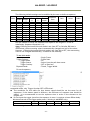
10. Operation modes...................................................................... - 55 10.1. Continuous mode (Free run) .........................................................................
The above figures are for pixel formats MONO8 or Bayer 8 .............................................
10.2. Trigger operation with “timed” exposure (Previously called EPS) ............................
10.2.1 TriggerOverlap = OFF............................................................................
10.2.2 TriggerOverlap = Read out .....................................................................
10.2.3 SmearLess ON .....................................................................................
10.3. Trigger operation by “TriggerWidth” (Previously called PWC) ................................
10.3.1 TriggerOverlap = OFF............................................................................
10.3.2 TriggerOverlap = Read out .....................................................................
10.4. Timed-Pre-dump mode (so-called RCT) (JAI Custom) ...........................................
10.5. Timed-PIV (Particle Image Velocimetry) (JAI Custom) ..........................................
10.6 Other JAI custom mode ................................................................................
10.6.1 Video Send Mode .................................................................................
-4-
- 55
- 56
- 56
- 57
- 57
- 57
- 58
- 59
- 59
- 60
- 61
- 62
- 62
-
AM-800GE / AB-800GE
10.6.1.1 Normal: Ordinal operation ................................................................. - 62
10.6.1.2 Sequence Trigger Mode ..................................................................... - 62
10.6.1.3 Multi ROI Mode ............................................................................... - 64
10.6.2 Delayed Readout Mode (JAI Custom Control) ............................................... - 64
10.6.3 OB transfer ........................................................................................ - 65
10.6.3.1 Vertical OB transferred ..................................................................... - 66
10.6.3.2 Horizontal OB transferred .................................................................. - 66
10.6.3.3 OB transfer is not activated ............................................................... - 67
10.7. Mode and function matrix table ..................................................................... - 67
-
11. Other functions ....................................................................... - 68 11.1. ALC ....................................................................................................... - 68
11.2 Black level control ...................................................................................... - 68
11.2.1 Black level control relations ................................................................... - 69
11.2.2 Black Level Selector ............................................................................. - 69
11.2.3 Black Level ........................................................................................ - 69
11.2.4 Black Level Auto ................................................................................. - 69
11.3. Gain control ............................................................................................. - 70
11.3.1 Gain control relations ........................................................................... - 70
11.3.2 Gain Control ...................................................................................... - 70
11.3.3 Gain selector ..................................................................................... - 71
11.3.4 Gain ................................................................................................ - 71
11.3.5 Gain Raw .......................................................................................... - 72
11.3.6 Gain Auto .......................................................................................... - 72
11.4. Tap Balance ............................................................................................. - 72
11.4.1 Gain Auto Balance ............................................................................... - 73
11.4.2 Automatic Tap Balance ......................................................................... - 73
11.4.3 Manual Tap Balance ............................................................................. - 73
11.4.4 Once Tap Balance ................................................................................ - 73
11.5. Exposure auto (Auto Shutter) ........................................................................ - 73
11.6. Balance Ratio (Only for AB-800GE) ................................................................. - 73
11.6.1 Balance Ratio ..................................................................................... - 73
11.6.2 Balance Ratio Auto .............................................................................. - 74
11.7. Blemish compensation ................................................................................ - 74
11.8. LUT ....................................................................................................... - 74
11.9 Gamma .................................................................................................... - 76
11.10. Shading Correction ................................................................................... - 77
11.11. Bayer color interpolation (Only for AB-800GE) .................................................. - 77
11.12. Test Image selector .................................................................................. - 78
11.13. Temperature sensor (Command : TMPO) ......................................................... - 78
-
12. Examples of operation using JAI Control Tool .................................. - 79 12.1. About GenICamTM SFNC1.3 ............................................................................ - 79
12.2. Examples of camera operation ...................................................................... - 79
12.2.1 Operational cautions ............................................................................. - 79
12.2.2 Connecting camera(s) ........................................................................... - 79
12.2.3 Camera setting layers ........................................................................... - 80
12.4. Input and output settings ............................................................................. - 81
12.4.1. Connection with the external devices ...................................................... - 81
12.4.2. Setting inputs and outputs .................................................................... - 82
12.4.2.1 Select signal to connect with Line which is selected by Line selector ............. - 82
12.4.2.2 Select Trigger Source ....................................................................... - 82
12.4.3. Specify the image size to be captured ...................................................... - 83
12.4.4. Acquisition of the image ....................................................................... - 84
12.4.4.1 Basic settings ................................................................................. - 84
12.4.5. Setting examples ................................................................................ - 86
12.4.5.1 Capture the image continuously with fastest frame rate ............................ - 86
12.4.5.2 Capture the image with half of the frame rate (increasing the sensitivity) ...... - 86
-5-
-
AM-800GE / AB-800GE
12.4.5.3 Capture one frame with preset exposure time using the external trigger ........ - 86
12.4.5.4 Capture multi frames of the image with preset exposure time using the external
trigger ...................................................................................................... - 87
12.4.5.5 Capture one frame image with the trigger width using the external trigger ..... - 87
12.4.5.6 Capture multi frames of the image with the trigger width using the external ... - 88
trigger ...................................................................................................... - 88
12.4.5.7 Capture the image continuously with preset exposure time by using the external
trigger ...................................................................................................... - 88
12.4.5.8 Capture the image using Software Trigger .............................................. - 88
12.4.5.9 Sequence Trigger setting ................................................................... - 89
12.4.5.10 Multi ROI setting ............................................................................ - 90
12.4.5.11 Delayed readout setting .................................................................. - 91
12.4.5.12 Operate the external strobe light ....................................................... - 91
12.4.6 How to view the XML file ....................................................................... - 92
12.4.7 Feature Tree Information ...................................................................... - 93
12.4.8 Feature Properties (Guru) ...................................................................... - 93
-
13. External Appearance and Dimensions .......................................... - 100 14. Specifications ........................................................................ - 102 14.1 Spectral response ...................................................................................... - 102 14.2 Specifications table .................................................................................... - 103 -
Appendix .................................................................................... - 105 1.
2.
3.
4.
5.
6.
Precautions................................................................................................. - 105
Typical Sensor Characteristics .......................................................................... - 105
Caution when mounting a lens on the camera ....................................................... - 105
Caution when mounting the camera ................................................................... - 106
Exportation ................................................................................................. - 106
References ................................................................................................. - 106
-
Change history ............................................................................. - 107 User's Record ............................................................................... - 108 -
-6-
AM-800GE / AB-800GE
JAI GigE® Vision Camera operation manuals
To understand and operate this JAI GigE® Vision camera properly, JAI provides the following
manuals.
User’s manual (this booklet)
JAI SDK & Control Tool User Guide
JAI SDK Getting Started Guide
Describes functions and operation of the hardware
Describes functions and operation of the Control Tool
Describes the network interface
User’s manual is available at www.jai.com
JAI SDK & Control Tool User Guide and JAI SDK Getting Started Guide are provided with the
JAI SDK which is available at www.jai.com.
Introduction
GigE Vision is the new standard interface using Gigabit Ethernet for machine vision
applications and it was mainly set up by AIA (Automated Imaging Association) members. GigE
Vision is capable of transmitting large amounts of uncompressed image data through an
inexpensive general purpose LAN cable for a long distance.
GigE Vision also supports the GenICamTM standard which is mainly set up by the EMVA
(European Machine Vision Association). The purpose of the GenICam standard is to provide a
common program interface for various machine vision cameras. By using GenICam, cameras
from different manufactures can seamlessly connect in one platform.
For details about the GigE Vision standard, please visit the AIA web site,
www.machinevisiononline.org and for GenICam, the EMVA web site, www.genicam.org.
JAI GigE Vision cameras comply with both the GigE Vision standard and the GenICam standard.
Before using GigE Vision camera
All software products described in this manual pertain to the proper use of JAI GigE Vision
cameras. Product names mentioned in this manual are used only for the explanation of
operation. Registered trademarks or trademarks belong to their manufacturers.
To use the JAI SDK, it is necessary to accept the “Software license agreement” first.
This manual describes necessary equipment and the details of camera functions.
Software installation
The JAI GigE Vision SDK & Control Tool can be downloaded from the JAI web site at
www.jai.com. The JAI SDK is available for Windows XP and Vista, 32-bit and 64-bit.
For the details of software installation, please refer to the “Getting Started Guide” supplied
on the JAI SDK download page.
-7-
AM-800GE / AB-800GE
Camera Operation
1. General
The AB-800GE and AM-800GE comply with the GigEVision® standard and also GenICamTM with
its Standard Feature Naming Convention (SFNC) ver.1.3. Functions described in this booklet
are described based on this standard.For further information about the GigE Vision standard,
please go to www.machinevisiononline.org and about GenICam, please go to
www.genicam.org.
The AM-800GE is a 4/3 inch monochrome progressive scan CCD camera and the AB-800GE is
the equivalent Bayer mosaic progressive scan CCD camera. Both have 8 million pixels
resolution and utilize 2-tap output from the Kodak KAI-08050 sensor. They provide 10 frames
per second (8-bit output) for continuous scanning with full 3296 x 2472 pixel resolution.
Both AM-800GE and AB-800GE are suitable for automated optical inspection applications, such
as solid state device inspection or material surface inspection.
They incorporate various processing circuits such as LUT, FFC (Flat Field Compensation),
blemish compensation and Bayer interpolation. The AM-800GE and AB-800GE work in
continuous, single frame, and multi-frame modes for acquisition control together with timed
and trigger width exposure controls. Both cameras also have pre-dump and PIV modes.
As an application programming interface, JAI provides an SDK (Software Development Kit).
This SDK includes GigE Vision Filter Driver, JAI control tool, software documentation and code
examples.
The JAI SDK can be downloaded from www.jai.com.
The latest version of this manual can be downloaded from www.jai.com
For camera revision history, please contact your local JAI distributor.
2. Camera nomenclature
The camera is available in the following versions:
AM-800GE-C
AM-800GE-F
Where A stands for "Advanced" family, M stands for "Monochrome", 800 represents the
resolution "8 million pixel" , GE stands for "GigEVision" interface and C for C-mount lens or F
for F-mount lens
AB-800GE-C
AB-800GE-F
Where A stands for "Advanced" family, B stands for "Bayer mosaic color", 800 represents the
resolution "8 million pixel" , GE stands for "GigEVision" interface and C for C-mount lens or F
for F-mount lens
-8-
AM-800GE / AB-800GE
3. Main Features
C3 Advanced series 4/3 ” progressive scan camera
Monochrome and Bayer mosaic color versions
3296 (h) x 2472 (v) active pixels
5.5μm square pixels
57dB or more S/N for AM-800GE and 55dB or more for AB-800GE
8-bit, 10-bit or 12-bit output for monochrome and Bayer, or 8-bit output RGB color or
YUV422 output for AB-800GE
10 frames/second with full resolution in continuous operation for monochrome or Bayer
8-bit output
3 frames/second for AB-800GE RGB output (in-camera interpolation) and 6.7
frames/second for AB-800GE YUV422 output
Various readout modes, horizontal and vertical binning (AM-800GE only) and AOI (Area
Of Interest) modes for faster frame rates
-3dB to +24dB gain control for AM-800GE and 0dB to +24dB for AB-800GE
10μs (1/100,000) to 2 seconds exposure control in 1μs steps ( Exposure/Timed control
mode)
Timed and trigger width for exposure control
Pre-dump (RCT) and PIV modes for specific applications
ALC to automatically control exposure for changing lighting conditions by combining
auto gain control, auto shutter and auto iris functions
Various pre-processing circuits are provided
Programmable LUT
Gamma correction from 0.45 to 1.0
Shading Correction
Bayer white balance with manual, one-push auto, or continuous (AB-800GE only)
Bayer color interpolation (AB-800GE only)
Blemish compensation
Test pattern signal generator built in
Auto iris lens video output with H-sync
Choice of lens mounts offered: C-mount or F-mount
Setup by Windows XP/Vista/7 via serial communication
-9-
AM-800GE / AB-800GE
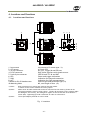
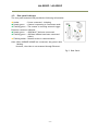
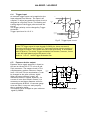
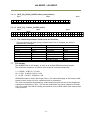
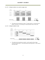
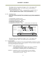
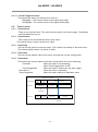
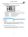
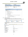
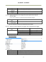
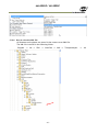
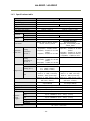
4. Locations and Functions
4.1. Locations and functions
①
⑥
⑦ ③
Top View
DC IN/TRIG
POWER/TRIG
LINK
⑩
ACT.
⑧
④
⑨
GigE
⑨
GPIO
②
⑤
Front View
Side View
Rear View
Bottom View
1. Lens mount
2. CCD sensor
3. 12-pin connector
4. RJ-45 connector
5. D-sub 9-pin connector
6. LED
7. LINK
8. ACT
9.Holes for RJ-45 thumbscrews
10.Mounting holes
*1) Note:
*2) Note:
*3) Note:
Lens mount of C-mount type. *1)
4/3 inch CCD
DC+12V, Trigger IN and EEN out
GigE Vision interface with thumb screws
LVDS IN and TTL IN and OUT
Power and trigger indications
Indication for Network connection
Indication for GigE communication
Vertical type and horizontal type (*2)
M3, max length 4.5mm (*3)
Rear protrusion on C-mount lens must be less than 10mm.
F mount version is also available as factory option.
When an RJ-45 cable with thumb screws is connected to the camera, please do not
excessively tighten screws by using a driver. The RJ-45 receptacle on the camera might
be damaged. For security, the strength to tighten screws is less than 0.147 Newton
meter (Nm). Tightening by hand is sufficient in order to achieve this.
The tripod adapter plate MP-41 can be used.
Fig. 1. Locations
- 10 -
AM-800GE / AB-800GE
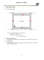
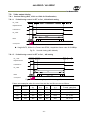
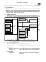
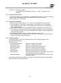
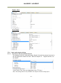
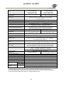
4.2. Rear panel indicator
The rear panel mounted LED provides the following information:
Amber
: Power connected - initiating
Steady green : Camera is operating in Continuous mode
Flashing green : The camera is receiving external trigger
Ethernet connector indicates,
Steady green : 1000 Base-T has been connected
Flashing green : 100 Base/10Base have been connected
(Note)
Flashing amber : Network active in communication
Note: When 100BASE/10BASE are connected, the green is also
flashing.
However, the video is not streamed through Ethernet.
Fig.2 Rear Panel
- 11 -
AM-800GE / AB-800GE
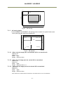
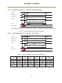
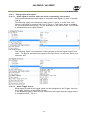
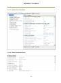
5. Pin Assignment
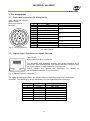
5.1. 12-pin Multi-connector (DC-IN/Digital IO)
Type: HR10A-10R-12PB-01
(Hirose) male.
(Seen from rear of
camera.)
9
1
2
8
10
11
3
4
7
12
5
6
Fig. 3. 12-pin connector.
Pin no.
Signal
Remarks
1
GND
+12V to +24V
2
DC input
3
Opt In 2(-) / GND (*1)
Line 6
4
Opt In 2 (+) / Iris video(*1)
5
Opt In 1 (-)
Line 5
6
Opt In 1 (+)
7
Opt Out 1 (-)Line 3
8
Opt Out 1 (+)
9
Opt Out 2 (-)
Line 4
10
Opt Out 2 (+)
+12V to +24V
11
DC input
12
GND
*1) Default is Opt In 2. DIP switch SW901 changes to
iris video output.
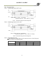
5.2. Digital Output Connector for Gigabit Ethernet
Type: RJ-45
HFJ11-1G02E-L21RL or equivalent
The AM-800GE AND AB-800GE cameras also accept industrial RJ-45
connectors with thumbscrews. This assures that the connector does
not come undone in tough industrial environments.
Please contact the nearest JAI distributor for details on
recommended industrial RJ-45 connectors.
Fig. 4. Gigabit Ethernet connector
The digital output signals follow the Gigabit Ethernet interface using RJ-45 conforming
connector. The following is the pin assignment for the Gigabit Ethernet connector.
Pin No
1
2
3
4
5
6
7
8
In/Out
In/Out
In/Out
In/Out
In/Out
In/Out
In/Out
In/Out
In/Out
Name
MX1+ (DA+)
MX1- (DA-)
MX2+ (DB+)
MX3+ (DC+)
MX3- (DC-)
MX2- (DB-)
MX4+ (DD+)
MX4- (DD-)
- 12 -
AM-800GE / AB-800GE
5.3. D-Sub 9pin connector (For GPIO)
Type : DD-09SSG
Fig. 5.D Sub
No
1
2
I/O
I
I
3
I
TTL IN 1
4
5
6
7
8
9
O
TTL Out 1
GND
NC
NC
TTL OUT 2
GND
O
Note1)
9pin connector
Name
Note
LVDS In 1LVDS In 1+
Line 8
Line 7
75ohm Termination (Note 1)
Line 1
Line 2
Can be changed by DIP switch (SW900).
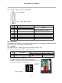
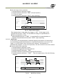
5.4. DIP switch
DIP switches are located on circuit boards. When the top cover is removed, please pay careful
attention so that circuit boards are not damaged.
5.4.1 SW-900
This switch sets the 75 ohm trigger input termination to ON or OFF.
The factory default setting is OFF which is TTL level.
No
Setting
Functions
ON
OFF
TTL
1
Trigger input termination
75Ω
2
NC
The 75 ohm termination DIP switch is located the right side as looking from the lens
when the top cover is removed.
The photo in the right shows the default setting.
In order to change to the 75 ohm termination, the switch
in the front should be set downwards.
Right side for
75 ohms
termination
ON
Fig.6. SW900
SW900
- 13 -
AM-800GE / AB-800GE
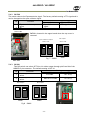
5.4.2 SW-500
This switch selects the ExposureActive signal. The factory default setting is TTL signal and it
can be changed to the open collector signal.
Setting
No
Function
ON
OFF
Exposure Active output
Open Collector
TTL signal
select
signal
2
NC
Sensor side
SW500 is located in the upper board when the top cover is
removed.
Open Collector ooutput
Sensor side
SW500
TTL output
Sensor side
SW500
Fig. 7 SW500
back side
5.4.3 SW-901
This DIP switch can select OPT IN or Iris video output through pin#3 and #4 of the
HIROSE 12 pin connector. The default setting is OPT IN.
Setting
No
Functions
ON
OFF
OPT IN(+) / Iris video OUT
1
Iris video
OPT IN (+)
select
OPT IN(-) / Iris video OUT
2
GND for iris video
OPT IN (-)
select
Opt output
SW901
Iris output
SW901
Fig.8 SW901
- 14 -
AM-800GE / AB-800GE
6. Input and output Interface
6.1. Digital Interface
In the AM-800GE AND AB-800GE, the input and output interfaces for Hirose 12P and DSub 9P are configured as follows.
6.1.1 LineSelector
The following input and output signals are configured on Line 1 through Line 8.
① Line 1(TTL out1)
② Line 2(TTL out2)
③ Line 3(Opt out1)
④ Line 4(Opt out2)
⑤ Line 5(Opt in1)
⑥ Line 6(Opt in2)
⑦ Line 7(TTL in1)
⑧ Line 8(LVDS in)
6.1.2 LineInverter
This function changes the polarity of the signal.
6.1.3 LineStatus
The user can ascertain the status of input and output signals.
6.1.4 LineSource
This function lets you designate the signal source to output through Line 1 to Line 4 as
part of the LineSelector configuration. Each signal is selected from the following
five signals.
① AcquisitionTriggerWait
② AcquisitionActive
③ FrameTriggerWait
④ FrameActive
⑤ ExposureActive
⑥ JAI_Acquisitionwait
⑦ Counter1Active
⑧ Timer1Active
⑨ UserOut0
⑩ UserOut1
⑪ UserOut2
⑫ UserOut3
6.1.5 LineMode
The current mode of signals (input or output) is displayed.
6.1.6 LineFormat
The interface of input and output circuits is displayed.
Output
Input
TTL
Line 1
Opt
TTL
Line 2
Opt
Opt
Line 3
TTL
Opt
Line 4
LVDS
- 15 -
Line
Line
Line
Line
5
6
7
8
AM-800GE / AB-800GE
6.2. Opto-isolated Interface
The control interface of the C3 GigE Vision
camera series has opto-isolated inputs and
outputs, providing galvanic separation between
the camera's inputs/outputs and peripheral
equipment. In addition to galvanic separation,
the opto-isolated inputs and outputs can cope
with a wide range of voltages; the voltage
range for inputs is +3.3V to +24V DC whereas
outputs will handle +5V to +24V DC.
The figure at the right shows the functional
principle (opto-coupler) of the opto-isolated
inputs/outputs.
Fig.9
Opto-coupler
6.2.1 Recommended External Input circuit diagram for customer
Fig.10
External Input Circuit, OPT IN 1 and 2
6.2.2 Recommended External Output circuit diagram for customer
Fig.11
External Output Circuit, OPT OUT 1 and 2
- 16 -
AM-800GE / AB-800GE
6.2.3 Optical Interface Specifications
The relation of the input signal and the output signal through the optical interface is as
follows.
Time Delay Rising
Rising Time
Falling Delay Time
Falling Time
3.3V
0.54
1.2
1.5
3.6
TDR(µs)
RT(µs)
FDR(µs)
FT(µs)
User Power (VCC)
5V
12V
0.54
0.62
1.2
2.0
1.5
2.4
3.4
4.5
24V
0.68
3.0
2.1
6.8
Fig.12 Optical Interface Performance
6.3. Iris video output
This signal can be used for lens iris control in Continuous
and pre-dump modes.
The signal is 1.0 V p-p (with H-sync) from 75 without
termination.
+5V
0.1μ
12K
DA IN
IRIS Video Out
DAC
12K
1K
1μ
10K
Iris Sync
Fig. 13 Iris video output.
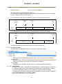
The iris video signal is composed to average the video level in the center area of each frame
and can be output as a composite signal with H-sync. As shown in the following figure, each
frame has its own video level which is averaged.
Fig.14
Iris signal details
- 17 -
AM-800GE / AB-800GE
The following parameters of this auto iris control signal output can be changed.
Auto Iris Control Signal Output:
ON : The auto iris control can be connected with AGC and ASC as ALC function
OFF : The auto iris control is not connected with AGC and ASC.
Iris Reverse Gain:
ON : The auto iris control signal is multiplied by the inverse of AFE gain (VGA
gain). If ALC is used, select this one. Auto iris control signal is not affected
by AGC gain.
OFF: The auto iris control signal is not multiplied by the inverse of AFE gain (VGA
gain).
Iris State Control:
Video: Use the iris control in auto mode.
Close: Force the iris to close.
Open: Force the iris to open.
Iris Sync Level: Adjust the H sync level added to the video between 0 to 255.
Iris Control Gain:
0 – 255: Set a separate control gain for the auto iris control signal. If oscillation
occurs when the auto iris diaphragm reaches the set point, this setting
may reduce the phenomenon.
Iris Interpolate Gain (Note):
0 – 255: At frame rates below 20fps, the auto iris operation may appear “jumpy”
as it rapidly moves from one level to the next.
This function prevents this so-called “hunting” phenomenon by
interpolating new auto iris control levels between each frame, thereby
smoothing the rate of the auto iris changes.
Iris Calculate Ratio (Note):
20 – 160: This function compensates Iris Interpolate Gain to allow for the varying
diaphragm ranges of different auto iris lenses.
This can be helpful if the auto iris is not able to find the appropriate
point by hunting when operating at frame rates of less than 20fps.
Note:
These interpolated controls are calculated based on the “Gain Auto
Reference” value. If the system is operating with a frame rate of less than
20fps, the set point of the lens should match the value of “Gain Auto
Reference”, even if ALC is being controlled by only the auto iris. Also, when
using an auto iris lens with its own speed and level controls, it is
recommended that these controls first be adjusted on the lens before using
the camera controls above to avoid possible conflicts.
- 18 -
AM-800GE / AB-800GE
6.4. Trigger input
An external trigger input can be applied to the
input selected Line Selector. The input is AC
coupled. To allow long pulses the input circuit is
designed as a flip-flop circuit. The leading and
trailing edges of the trigger pulse activate the
circuit.
The trigger polarity can be changed by Trigger
Activation.
Trigger input level is 4 V 2 V.
+5V
●
●
15K
Trigger
IN
●
●
●
3K
1K
0.1μ
●
100K
●
22K
1K
+5V
●
Trigger INI B
○
Trigger INI A
0.1μ
1000
●
Fig.15 Trigger input circuit
Initial Trigger Activation Set:
If the TTL trigger signal is input through D-SUB 9 pin, there are several
functions inside the camera using TTL. And each function has the setting of
the trigger activation, the camera sets the initial processing in accordance
with its priority. The initial Trigger Activation Set function, however, forces
to set the input polarity after the power is ON.
Refer to 9.2.4.1 Initial Trigger Activation Set.
6.5. Exposure Active output
Exposure Active signal (positive) is found on
Opt-out on Hirose 12P or TTL out on D-sub
9-pin connector. The output circuit is 75
complementary emitter followers. Output
level 3 V from 75 (no termination). It can
be changed to the open collector signal.
When the open collector is used, the
maximum current is 120mA. However, if a
current of more than 50mA is flowed, it is
necessary to use bigger diameter wires for
connecting pins #8 and 9. If narrower-gauge
wires are used, it may not work properly
due to resistance issues.
This output can be changed to open collector
signal by SW500.
+5V
10
150
●
10K
- 19 -
●
220
Exposure
Active
●
●
120
●
TTL
10
0.1μ
SW500
●
○
●
+5V
10K
●
180
100
●
●
●
0.1μ
Open
Collector
1K
1K
●
Fig.16
●
●
Exposure Active output
TTL Out
1/2
AM-800GE / AB-800GE
7. Video signal output
7.1. Video output image
*1
*2
*2
Note: The following OB area can be transferred.
For vertical : 4 pixels in *1
For horizontal : 16 pixels each in *2
Fig.17 CCD sensor layout
7.2. AOI (Area of Interest)
In the AM-800GE and AB-800GE, the output image size can be determined by setting
the output area.
7.2.1
AOI parameters
In order to set the output area, 4 parameters including OffsetY, OffsetX, Width and
Height should be specified.
- 20 -
AM-800GE / AB-800GE
(1,1)
OffsetY
HeightMax
Height
OffsetX
Width
WidthMax
Fig.18
7.2.2
AOI setting
AOI setting details
In the AM-800GE and AB-800GE, AOI settings must consider the optical black areas
when specifying the area to be transferred.
(1,1)
(3328,1)
OB 4 lines
OB 16 pixels
(3312,4)
(16,4)
Height
OB 16 pixels
Width
(3312,2476)
(16,2476)
(1,2476)
(3328,2476)
Fig.19 OB transfer
7.2.2.1 When only the image part is transmitted (OB is not transferred)
Offset X=16
Offset Y=4
Width =3296
Height = Effective lines
7.2.2.2 When the full image plus the vertical OB is transmitted
Offset X=16
Offset Y=0
Width =3296
Height = Effective lines +4
7.2.2.3 When the full image plus the horizontal OB is transmitted
Offset X=0
Offset Y=4
Width =3328
Height = Effective lines
Note: When the horizontal OB is transferred, the width must be set at its maximum.
- 21 -
AM-800GE / AB-800GE
7.2.3 Frame rate calculation in the AOI mode
The frame rate in AOI mode depends on each setting of Offset, Height, Bit allocation
or Binning control. In the following formulas, the part labelled (
round down ) has its
decimal values rounded down.
7.2.3.1 Binning control setting : off or 1x2
If Offset is less 4, Offset is regarded as 4.
start_area_num = ((OffsetY - 4)/4)round down) x 4
end_area_num = (((2471 – (Height + OffsetY -5))/4)round down ) x 4
Frame line number =
(start_area_num / 4) + (( 2471 – end_area_num) – start_area_num + 1) +
(end_area_num / 4) + 52
Frame rate (Hz) = 1/ (Frame line number x 0.00003879 )
Setting examples
Area
Offset
Frame rate
(fps)
Height
1/2
622
1236
1/4
932
618
1/8
1086
310
Continuous
Timed (EPS)
(Smearless OFF)
Trigger Width
Continuous
Timed (EPS)
(Smearless OFF)
Trigger Width
Continuous
Timed (EPS)
Trigger Width
16.11
22.71
28.51
7.2.3.2 Binning control setting : 2x1 or 2x2
If Offset is less 4, Offset is regarded as 4.
start_area_num = (((OffsetY x 2) – 8)/4)round down) x 4
end_area_num = (((2471 – (Height x 2) + (OffsetY x 2) -9))/4)round down ) x 4
Frame line number =
(start_area_num / 4) + (( 2471 – end_area_num) – (start_area_num + 1)/2) +
(end_area_num / 4) + 26
Frame rate (Hz) = 1/ (Frame line number x 0.000042125 )
- 22 -
AM-800GE / AB-800GE
Setting example
Area
Offset
1/2
314
618
1/4
468
308
1
544
156
/8
Frame rate
(fps)
Height
Continuous
Timed (EPS)
(SmearLess OFF)
Trigger Width
Continuous
Timed (EPS)
(SmearLess OFF)
Trigger Width
Continuous
Timed (EPS)
Trigger Width
24.90
29.74
32.87
7.2.4 The relationship between LinePitch and Width
The setting range of LinePitch is changed according to PixelFormat setting.
LinePitch can be set as follows.
Mono8/Bayer8
: 8-3328, by 8 pixels step
Mono10/Bayer10_Packed
: 12-4992, by 12 pixels step
Mono10/12/bayer10/12
: 16-6656, by 16 pixels step
RGB8_Packed
: 24-9984, by 24 pixels step
YUV422_Packed
: 16-6656, by 16 pixels step
As for LinePitch and Width, if one is changed, the other will also be changed.
The relationship between LinePitch and width is;
Mono8/Bayer8
: Linepitch
Mono10/Bayer10_Packed
: Linepitch/1.5
Mono10/12/Bayer10/12
: Linepitch/2
RGB8_Packed
: Linepitch/3
YUV422_Packed
: Linepitch/2
7.3. In case of vertical binning and horizontal binning (Only for AM-800GE)
This function is available only for AM-800GE. In binning mode, adjacent pixels in the
horizontal direction and/or vertical direction are combined and output as one pixel.
The possible combinations are shown below.
Horizontal
2 pixels
2 Pixels
Vertical
1 Pixel
1 pixel
Fig. 20 Binning modes
- 23 -
AM-800GE / AB-800GE
Binning achieves a higher frame rate, as well as better sensitivity.
On the other hand, the resolution becomes less than the full frame readout.
Spatial resolution
H x V (Pixels)
Sensitivity
H direction
V direction
1x2
2 times
Unchanged
1/2
2x1
2 times
1/2
Unchanged
2x2
4 times
1/2
1/2
7.3.1 The relationship between Binning Horizontal and Width/LinePitch
If Binning Horizontal is set at 1 or 2, Width/LinePitch is changed accordingly.
Binning Horizontal = 1 Width is 3328 as the maximum
Binning Horizontal = 2 Width is 1664 as the maximum
Note: If Binning Horizontal is reset to 1 after setting to 2, the maximum value is not
changed. It is necessary to set manually.
7.3.2 The relationship between Binning Vertical and Height
If Binning Vertical is set at 1 or 2, Height is changed accordingly.
Binning Vertical = 1 Height is 2476 as the maximum
Binning Vertical = 2 Height is 1240 as the maximum
Note: If Binning Vertical is reset to 1 after setting to 2, the maximum value is not changed.
It is necessary to set manually.
7.4. Digital video output (Bit allocation)
Although the AM-800GE and AB-800GE are digital cameras, the image is generated by an
analog component, the CCD sensor. The table and diagram below show the relationship
between the analog CCD output level and the digital output.
CCD out
Digital Out
Analog Out
(Equivalent)
8bit
10bit
12bit
Black
0%
Setup 3.6%, 25mV 8LSB
32LSB
128LSB
AM-800GE 350mV
100%
700mV
222LSB 890LSB 3560LSB
AB-800GE 290mV
AM-800GE 404mV
115%
808mV
255LSB 1023LSB 4095LSB
AB-800GE 334mV
1023
White Clip Level
890
Digital Out [LSB]
100% Level
32
0
Black Level
25
Analog Out [mV]
700 800
Fig.21 Bit allocation
- 24 -
AM-800GE / AB-800GE
7.5. Bayer output pattern
The AB-800GE starts with GRG on odd lines and BGB on even lines as shown below.
If AOI is used, Offset Y can be set every 2 lines and therefore, it always starts with a
GRG sequence.
signal out
H1
H2
H3
H4
H5
H6
H7
V1
Gr
R
Gr
R
Gr
R
Gr
V2
B
Gb
B
Gb
B
Gb
B
V3
Gr
R
Gr
R
Gr
R
Gr
Fig. 22 Bayer sequence
7.6. Pixel format and pixel type
In the GigE Vision Interface, GVSP (GigE Vision Streaming Protocol) is used for an
application layer protocol relying on the UDP transport layer protocol. It allows an
application to receive image data, image information and other information from a
device.
As for the sensors in the AM-800GE AND AB-800GE, the following pixel types supported
by GVSP are available.
With regard to the details of GVSP, please refer to the GigE Vision Specification
available from the AIA (www.machinevisiononline.org).
Model
AM-800GE
AB-800GE
Pixel Type supported
Mono8, Mono10, Mono10_Packed, Mono 12, Mono12_Packed
BayGR8, BayGR10, BayGR12, BayGR10_Packed,
BayGR12_Packed,RGB8_Packed, GVSP_PIX_YUV422_PACKED
7.6.1 GVSP_PIX_MONO8 (8bit output)
Y0
Y1
Y2
0 1 2 3 4 5 6 7 0 1 2 3 4 5 6 7 0 1 2 3 4 5 6 7
7.6.2 GVSP_PIX_MONO10 (10bit output)
Y0
Y0
Y1
Y1
0 1 2 3 4 5 6 7 8 9 X X X X X X 0 1 2 3 4 5 6 7 8 9 X X X X X X
7.6.3 GVSP_PIX_MONO10_Packed (10bit output)
Y0
Y1
Y2
Y3
2 3 4 5 6 7 8 9 0 1 X X 0 1 X X 2 3 4 5 6 7 8 9 2 3 4 5 6 7 8 9 0 1 X X 0 1 X X 2 3 4 5 6 7 8 9
7.6.4 GVSP_PIX_MONO12 (12bit ourput)
Y0
Y0
Y1
Y1
0 1 2 3 4 5 6 7 8 9 10 11 X X X X 0 1 2 3 4 5 6 7 8 9 10 11 X X X X
- 25 -
AM-800GE / AB-800GE
7.6.5 GCSP_PIX_MONO12_Packed (12bit output)
Y0
Y1
Y2
Y3
4 5 6 7 8 9 10 11 0 1 2 3 0 1 2 3 4 5 6 7 8 9 10 11 4 5 6 7 8 9 10 11 0 1 2 3 0 1 2 3 4 5 6 7 8 9 10 11
7.6.6 GCSP_PIX_BAYERGR8 (8bit output)
Odd Line
G0
R1
G2
0 1 2 3 4 5 6 7 0 1 2 3 4 5 6 7 0 1 2 3 4 5 6 7
Even Line
B0
G1
B2
0 1 2 3 4 5 6 7 0 1 2 3 4 5 6 7 0 1 2 3 4 5 6 7
7.6.7 GVSP_PIX_BAYERGR10 (10bit output)
Odd Line
G0
G0
R1
R1
0 1 2 3 4 5 6 7 8 9 X X X X X X 0 1 2 3 4 5 6 7 8 9 X X X X X X
Even Line
B0
B0
G1
G1
0 1 2 3 4 5 6 7 8 9 X X X X X X 0 1 2 3 4 5 6 7 8 9 X X X X X X
7.6.8 GVSP_PIX_BAYERGR10_Packed
Odd Line
G0
R1
2 3 4 5 6 7 8 9 0 1 X X 0 1 X X 2 3 4 5 6 7 8 9
Even Line
B0
G1
2 3 4 5 6 7 8 9 0 1 X X 0 1 X X 2 3 4 5 6 7 8 9
7.6.9 GVSP_PIX_BAYERGR12 (12bit output)
Odd Line
G0
G0
R1
R1
0 1 2 3 4 5 6 7 8 9 10 11 X X X X 0 1 2 3 4 5 6 7 8 9 10 11 X X X X
Even Line
B0
B0
G1
G1
0 1 2 3 4 5 6 7 8 9 10 11 X X X X 0 1 2 3 4 5 6 7 8 9 10 11 X X X X
7.6.10 GVSP_PIX_BAYERGR12_Packed
Odd Line
G0
R1
4 5 6 7 8 9 10 11 0 1 2 3 0 1 2 3 4 5 6 7 8 9 10 11
Even Line
B0
G1
4 5 6 7 8 9 10 11 0 1 2 3 0 1 2 3 4 5 6 7 8 9 10 11
- 26 -
AM-800GE / AB-800GE
7.6.11 GVSP_PIX_RGB8_PACKED (24bit) (Interpolation)
1Byte
2Byte
3Byte
R R R R R R R R G G G G G G G G B B B B B B B B
0 1 2 3 4 5 6 7 0 1 2 3 4 5 6 7 0 1 2 3 4 5 6 7
7.6.12 GVSP_PIX_ YUV422_PACKED (16bit)
1Byte
2Byte
3Byte
4Byte
U U U U U U U U Y Y Y Y Y Y Y Y V V V V V V V V Y Y Y Y Y Y Y Y
0 1 2 3 4 5 6 7 0 1 2 3 4 5 6 7 0 1 2 3 4 5 6 7 0 1 2 3 4 5 6 7
7.6.13 The relationship between PixelFormat and PixelSize.
The pixel format and pixel size are related and if one is changed, the other is
automatically changed.
Pixel format
Mono8
Mono10
Mono10_Packed
Mono12
Mono12_Packed
AM-800GE
Pixel size
Bpp8
Bpp16
Bpp12
Bpp16
Bpp12
Pixel format
AB-800GE
Pixel size
BayerGR8
BayerGR10
BayerGR10_Packed
BayerGR12
BayerGR_Packed12
RGB8_Packed
YUV422_Packed
Bpp8
Bpp16
Bpp12
Bpp16
Bpp12
Bpp24
Bpp16
7.7 YUV output
The AB-800GE has a YUV output, as well as an ordinal RGB interpolated output.
The conversion formula is as follows and cannot be controlled externally.
Y = 0.299*R + 0.587*G + 0.114*B
Cb = 0.5*B – 0.169*R -0.331*G +128
Cr = 0.5*R – 0.419*G – 0.0813*B + 128
While RGB output is 24-bit (8 bits per color), YUV takes advantage of the human visual
system's lower acuity for color variations than for luminance.
The color information (chrominance) is sub-sampled at half the rate of the brightness
component (luminance). Thus, YUV can be compressed into 16-bit output for a faster
full color frame rate that is visually perceived as close to RGB, albeit with lower actual
color precision.
- 27 -
AM-800GE / AB-800GE
7.8. Video output timing
7.8.1 Vertical timing (8bit, 10 bit or 12bit for Bit allocation)
7.8.1.1 If the binning control is OFF or 2x1, AOI default setting
Int_ LVAL
ExposureActive
FrameActive
Int_ FVAL
2524L
26L
15L
11L
2472L
DATA
OB BF
BF OB
Valid data
BF OB
CCD Exposure
Height:2472, Offset Y:4,Frame rate:2524L, Acquisition frame rate:10.21388fps
Fig.23
Vertical timing (AOI default)
7.8.1.2 If the binning control is OFF or 2x1, AOI setting
Int_ LVAL
ExposureActive
FrameActive
Int_ FVAL
Total line
26L
DATA
BF OB
A
B
OB BF
Valid
C
data
BF OB
CCD Exposure
Fig.24 Vertical timing for partial scanning (AOI)
Frame rate examples when the start line and the end line are set as follows
A
B
C
Total line
Acquisition
Offset
HEGHT
(L)
(L)
(L)
(L)
Frame rate(fps)
416
1648
118
1648
114
1906
13.52562
622
1236
171
1236
167
1600
16.11240
932
618
247
618
244
1135
22.71352
1086
310
287
310
281
904
28.51752
- 28 -
AM-800GE / AB-800GE
7.8.1.3 If the binning control is 1x2 or 2x2, AOI default setting
Int_ LVAL
ExposureActive
FrameActive
Int_ FVAL
1262 L
12L
DATA
9L
OB BF
BF OB
5L
1236 L
Valid data
BF OB
CCD Exposure
Height:1236, Offset Y:4, Frame rate: 1262L, Acquisition frame rate:18.81052fps
Fig.25 Vertical timing for the vertical binning
7.8.1.4 If the binning control is 1x2 or 2x2, AOI setting
Int_ LVAL
ExposureActive
FrameActive
Int_ FVAL
Total line
12L
DATA
BF OB
A
B
OB BF
Valid
C
data
BF OB
CCD Exposure
Fig.26 Vertical timing (Vertical binning, AOI setting)
210
824
A
(L)
112
314
618
164
618
159
953
24.90962
468
308
241
308
237
798
29.74796
544
156
279
156
275
722
32.87933
Offset
HEGHT
B
(L)
824
C
(L)
108
Total line
(L)
1056
Frame rate
(Hz)
22.47999
- 29 -
AM-800GE / AB-800GE
7.8.2 Horizontal timing
7.8.2.1 If the binning control is OFF or 2x1
1LVAL 1862clk = 38.79μs 1clk=20.83ns
(Exposure start line 1LVAL 1982 clk = 41.30μs)
Fig.27
Horizontal timing (Vertical binning OFF)
7.8.2.2 If the binning control is 1x2 or 2x2
1LVAL 2022clk = 42.13μs 1clk=20.83ns
(Exposure starting line 1LVAL 2182 clk = 45.46μs)
Fig.28 Horizontal timing (Vertical binning ON)
7.8.2.3 LVAL-LOW level period
1. When waiting for a trigger signal or at the exposure start line, LVAL-LOW period
varies as shown in the following table.
Binning Control
OFF, 2x1
1x2, 2x2
LVAL-LOW period
Ordinary Exposure start
186clk
306clk
346clk
506clk
- 30 -
LVAL cycle
Ordinary
Exposure start
1862ck 38.79 us 1982ck 41.30 us
2022ck 42.13 us 2182ck 45.46 us
AM-800GE / AB-800GE
EEN
LVAL
The first occurrence after the exposure start line:
LVAL-LOW period varies
“186clk ⇒ 306clk” (Binning Vertical=1, OFF, 2x1)
“346clk ⇒ 506clk” (Binning Vertical=2, 1x2, 2x2)
Fig.29 LVAL-LOW period varies
2. When the trigger control mode is set to ON and Overlap is set to Readout,
LVAL-LOW period is 1LVAL as the maximum.
Trigger
EEN
LVAL
Maximum 2 LVAL + LVAL Low period
Fig.30 LVAL-LOW period if Overlap is set to Readout
- 31 -
AM-800GE / AB-800GE
8. Network configuration
For details of the network settings, please refer to the “Getting Started
Guide” supplied with the JAI SDK.
8.1. GigEVision Standard interface
The AM-800GE / AB-800GE is designed in accordance with the GigE Vision standard.
Digital images are transmitted over Cat5e or Cat6 Ethernet cables. All camera
functions are also controlled via the GigE Vision interface.
The camera can operate in Continuous mode, providing an endless stream of images.
For capturing individual images related to a specific event, the camera can also be
triggered. For precise triggering, it is recommended to use a hardware trigger applied
to the Hirose 12-pin connector. It is also possible to initiate a software trigger through
the GigE Vision interface. However, when using a software trigger, certain latency
inherent to the GigE interface must be expected. This latency, which manifests itself
as jitter, greatly depends on the general conditions and traffic on the GigE connection.
The frame rate described in this manual is for the ideal case and may deteriorate
depending on conditions.
When using multiple cameras (going through a switch and/or a single path) or when
operating in a system with limited transmission bandwidth the Delayed Readout Mode
and Inter-Packet Delay functions can be useful.
8.2. Equipment to configure the network system
8.2.1 PC
The PC used should have the following performance or better
1) Recommended CPU
: Core2 Duo 2.4GHz or better,
Better than Core2 Extreme
2) Recommended memory
: 2Gbyte or more
3) Video card
: Better than PCI Express Bus Ver.1.0 x16
VRAM should be better than 256MByte, DDR2
4) Other
: The resident software should not be used
8.2.2 Cables
GigEVision configures the system by using 1000BASE-T.
In the market, CAT5e (125MHz), CAT6 (250MHz) and CAT7 (600MHz) cables are
available for 1000BASE-T. There are crossover cables and straight through cables
available. Currently, as most equipment
complies with Auto MDI/MDI-X, please use straight through cables. (Among crossover
cables, a half crossover type exists, which the Ethernet will recognize as 100BASE-T).
8.2.3 Network card (NIC)
The network card should comply with 1000BASE-T and also have the capability of
JUMBO FRAMES. When the jumbo frame size is set at a larger number, the load on the
CPU will be decreased. Additionally, as the overhead of the packet is decreased, the
transmission will have more redundancy.
JAI confirms the following network cards.
- 32 -
AM-800GE / AB-800GE
NIC
Manufacture Type
Intel
PRO/1000MT
Server Adapter
Intel
PRO/1000MT Dual Port
Server Adapter
Intel
PRO/1000GT Quad
Port
Server Adapter
Intel
PRO/1000PT
Server Adapter
Intel
Pro/1000 CT
Desktop adaptor
Intel
Gigabit ET2 Quad port
Server Adapter
Intel
Gigabit ET Dual port
Server Adapter
Intel
Gigabit EF Dual port
Server Adapter
PCI-X Bus
PCI-Express
Bus
―
( x1 )
―
( x1 )
―
( x4 )
―
( x4 )
―
( x4 )
32bit or 64bit
33/66/100/133 MHz
32bit or 64bit
33/66/100/133 MHz
32bit or 64bit
66/100/133 MHz
2.5Gbps uni-directional
5Gbps bi-directional
2.5Gbps uni-directional
5Gbps bi-directional
10Gbps uni-directional
20Gbps bi-directional
10Gbps uni-directional
20Gbps bi-directional
10Gbps uni-directional
20Gbps bi-directional
8.2.4 Hub
It is recommended to use the metal chassis type due to the shielding performance.
As the hub has a delay in transmission, please note the latency of the unit.
8.3. Recommended Network Configurations
Although the AM-800GE and AB-800GE conforms to Gigabit Ethernet (IEEE 802.3) not all
combinations of network interface cards (NICs) and switches/routers are suitable for
use with the GigE Vision compliant camera.
JAI will endeavor to continuously verify these combinations, in order to give users the
widest choice of GigE components for their system design.
For details of the network settings, please refer to the “Getting Started
Guide” supplied with the JAI SDK.
8.3.1
Guideline for network settings
To ensure the integrity of packets transmitted from the camera, it is recommended to
follow these simple guidelines:
1. Whenever possible use a peer-to-peer network.
2. When connecting several cameras going through a network switch, make sure it is
capable of handling jumbo packets and that it has sufficient memory capacity.
3. Configure inter-packet delay to avoid congestion in network switches.
4. Disable screen saver and power save functions on computers.
5. Use high performance computers with multi-CPU, hyper-thread and 64-bit CPU,
etc.
6. Only use Gigabit Ethernet equipment and components together with the camera.
7. Use at least Cat5e and preferably Cat6 Ethernet cables.
8. Whenever possible, limit the camera output to 8-bit.
- 33 -
AM-800GE / AB-800GE
8.3.2 Video data rate (network bandwidth)
In the GigE Vision Interface, it is important to know the packet data volume in order
to configure the system. the following table shows the reference value for each
output at Normal Mode (AcquisitionMode Continuous, FrameTrigger OFF).
Model
Pixel Type
Frame Rate
AM-800GE
MONO8
MONO10_PACKED
MONO12_PACKED
MONO10
MONO12
BAYGR8
BAYGR10_PACKED
BAYGR12_PACKED
BAYGR10
BAYGR12
RGB8_PACKED
YUV422Packed
10.2Frame/s
9.0 Frame/s
Packet size (Packet size is
1500)
693Mbps
923Mbps
6.7Frame/s
916Mbps
10.2Frame/s
9.0Frame/s
768Mpbps
923Mbps
6.7Frame/s
916Mbps
3.0 Frame/s *1)
6.7 Frame/s
4.5fps+ Shutter OFF (98mS)
916Mbps
AB-800GE
*1) In the case of RGB output, it is calculated as 4.5fps+ExposureTime (Shutter OFF, 98mS).
*2) The above data is if OB transfer mode is ON.
*3) If Jumbo Frames are not used, the frame rate except MONO8 and BAYGR8 will be
reduced by maximum 2%. Depending on Pixel Type, if Jumbo frames are used, the
packet size may be automatically optimized to a smaller size.
8.3.2.1 Exposure function in Mono, Bayer and YUV outputs
During sensor readout, the next exposure will start
Next
Exposure
Exposure
1,2,3 -------------2471,2472Line
SensorReadOut Tap1,2
Next
SensorReadOut Tap1,2
1,2,3 -------------------2471,2472Line
Transfer
Fig. 31 Exposure behavior
- 34 -
AM-800GE / AB-800GE
8.3.2.2 Exposure function in RGB output
After the stream is completed, the next exposure will start.
Next
Exposure
Exposure
1,2,3 -------------2471,2472Line
Next
SensorReadOut Tap1,2
SensorReadOut Tap1,2
1,2,3 ------------------------2471,2472Line
Transfer
RGB8_PACKED : 222ms ≒ 4.5fps
Fig. 32 Exposure behavior (RGB output)
8.3.3 Note for setting packet size
The packet size is set to 1428 as the factory default. Users may enter any value for the
packet size and the value will be internally adjusted to an appropriate, legal value that
complies with the GenICam standard. The packet size can be modified in the GigE
Vision Transport Layer Control section of the camera control tool.
Regarding data transfer rate, a larger packet size produces a slightly lower data
transfer rate. The AM-800GE and AB-800GE can support a maximum of 16020 byte
packets provided the NIC being used has a Jumbo Frames function with a setting of a
16020 bytes or larger.
Caution: Do not set the packet size larger than the maximum setting available in
the NIC or switch to which the camera is connected . Doing so will cause
output to be blocked.
The usable packet size for each output is shown in the following table.
Output
8bit
10bit_Packed, 12bit_Packed
10bit,12bit
RGB 8bit
YUV422
Usable packet size
36 + 8 x n
36 + 12 x n
36 + 16 x n
36 + 24 x n
36 + 16 x n
- 35 -
34 ≤ n ≤ 3488
31 ≤ n ≤ 320
29 ≤ n ≤ 296
25 ≤ n ≤ 258
29 ≤ n ≤ 296
AM-800GE / AB-800GE
8.3.4 Calculation of Data Transfer Rate
In order to calculate the data transfer rate, the following parameters and formula are
required.
Setting parameter
Item
Image Width
Image Height
Unit
[pixels]
[pixels]
Symbol
A
B
Bits per Pixel
[bits]
C
[fps]
[Bytes]
D
E
[packets]
G
[Mbit/s]
J
Unit
[Bytes]
[Bytes]
value
90
64
Frame Rate
Packet Size
Number of Packets (including Data Leader & Trailer
Packet)
Data Transfer Rate
Fixed value
Item
Data Leader Packet Size
Data Trailer Packet Size
Formula to calculate Data Transfer Rate
J={90+64+(E+18)*(G-2)}*8*D/1000000
Where, G=ROUNDUP{A*B*C/8/(E-36)}+2
The following table shows Bits per Pixel (Item C) which depends on the pixel format.
Pixel format
RGB8,bayerGR8
Mono10_Packed,Mono12_Packed
Bayer10_Packed, ayer12_Packed
Mono10, Mono12
Bayer10, Bayer12
RGB8_Packed
YUV422Packed
Bit
8
12
12
16
16
24
16
Calculation example: AM-800GE/AB-800GE Pixel type Mono/Bayer8
Item
Image Width (Max)
Image Height (Max)
Bits per Pixel
Frame Rate
Packet Size
Number of Packets (including Data Leader & Trailer
Packet)
Data Transfer Rate
Unit
[pixels]
[pixels]
[bits]
[fps]
[Bytes]
Symbol
A
B
C
D
E
[packets]
G
[Mbit/s]
J
G=ROUNDUP {(3328 x 2476 x 8 / 8 / (1500-36)) + 2 = 5629 + 2 = 5631
J={90+62+(1500+18)x(5631-2)} x 8 x 10.2 / 1000000 = 693 Mbit/s
- 36 -
Setting
3328
2476
8
10.2
1500
AM-800GE / AB-800GE
8.3.5 Simplified calculation (Approximate value)
A simple way to calculate the approximate data transfer rate is the following.
Transfer data = image width (pixel) x Image Height (pixel) x depth per pixel
(depending on the pixel format) x frame rate / 1,000,000 (convert to mega bit)
In the case of the AM-800GE and AB-800GE with the full image and Mono 8bit pixel
format;
The data transfer rate = 3328 x 2476 x 8 x 10.2 / 1000000 = 673 Mbit/s
8.4. GigE camera connecting examples
8.4.1 Using a switching hub for 1 port
All cameras and NIC belong to the same subnet
The accumulated transfer rate for all cameras should be within 800Mbps
The packet size and the packet delay should be set appropriately in order
for the data not to overflow in the switching hub.
- 37 -
AM-800GE / AB-800GE
8.4.2 Connecting a camera to each port of a multi-port NIC
This is the example for using a 4-port NIC
The pair of the connecting camera and the NIC constructs one subnet. As for
the IP configuration, it is appropriate to use the persistent IP.
In this case, each camera can use the maximum 800Mbps band width.
However, the load for the internal bus, CPU and the application software
become heavy, so a powerful PC will most likely be required.
8.4.3 The data transfer for multiple cameras
8.4.3.1 If delayed readout is not used in continuous mode
The packet delay should be set larger. The data traffic is controlled by the
buffer of the hub. It is necessary to check the buffer value of the unit.
- 38 -
AM-800GE / AB-800GE
8.4.3.2 If delayed readout is not used in trigger mode
The packet delay should be set larger. The data traffic is controlled by the
buffer of the hub. It is necessary to check the buffer value of the unit.
8.4.3.3 If delayed readout is used
The packet delay should be set smaller, and the packet delay trigger
controls the data traffic. If the camera has a pulse generator, it can control
the data traffic.
- 39 -
AM-800GE / AB-800GE
9. Core functions
The function naming of the AM-800GE and AB-800GE complies with GenICam SFNC
ver.1.3.
Most of the camera’s core operation is controlled by a combination of standard GenICam
features related to acquisition, triggering, and exposure. Additional control is provided
via built-in counter, timer, and event functions.
9.1. Acquisition function
Before using trigger and exposure controls, various acquisition controls must be set.
The operation of the camera depends on the interrelationship of all three feature sets.
Trigger Mode
[JAI Acquisition
Transfer Start]
Acquisition Start
Stream Control
Acquisition Stop
Internal
Stream
Control
Acquisition Abort
Trigger
Selector
[Acquisition
Start]
Acquisition
Status
Acquisition Status Control
Acquisition
State
Control
Trigger
Selector
[Acquisition
Stop]
Acquisition Mode
Acquisition Frame count
Trigger Selecctor
[Frame Start]
Exposure Control
Internal
Exposure
Control
Trigger Selector
[Exposure Start]
Trigger Selector
[Exposure End]
Acquisition Frame Rate
Acquisition Control
Trigger / Exposure Control
Active
Fig.34 Acquisition control, Trigger/Exposure control work flow
9.1.1 Basic image acquisition flow
The basic commands for acquiring images are as follows:
Acquisition mode
To determine the number of the frame to be captured
Trigger Selector
Acquisition Start Trigger Select if the acquisition start is controlled externally
Acquisition End
Select if the acquisition end is controlled externally
Trigger Selector
Frame start
Select if the acquisition of the frame is controlled
externally.
- 40 -
AM-800GE / AB-800GE
Exposure mode
To set the exposure method
The flow of these commands is shown below.
The following drawings are based on the conditions that the Acquisition mode is Single
and the Trigger selector is Frame Start.
If the acquisition start is set at ON (The acquisition is controlled externally)
Acquisition
Start
Command
Executed
Acquisition
Start
Trigger
Acquisition
Trigger Wait
Acquisition
Status
Acquisition
Start
Trigger
Frame Start
Trigger
Frame Start
Trigger Wait
Acquisition Active
Acquisition
Trigger Wait
If the acquisition start is set at OFF (The acquisition is controlled internally)
Acquisition
Start
Command
Executed
Acquisition
Status
Frame Start
Trigger
Frame Start
Trigger Wait
Frame Start
Trigger
Acquisition Active
Frame Start
Trigger Wait
The following sections provide the details for each command set.
9.1.2 Acquisition mode
The AM-800GE and AB-800GE has three settings for capturing images.
Single frame
AcquisitionStart command outputs one frame. Then the acquisition is stopped.
MultiFrame
AcquisitionStart command outputs frames which are set by AcquisitionFrameCount.
After the set frames are output, the acquisition is stopped.
Continuous
AcquisitionStart command outputs frames until AcquisitionEnd is initiated.
9.1.2.1 Single Frame
In single frame mode, executing the AcquisitionStart command causes one frame to
be captured. After one frame is captured, this operation is automatically stopped.
In order to restart the capture, it is necessary to input the AcquisitionStart
command again. BlockID is not reset until AcquisitionEnd is input and is incremented
when the AcquisitionStart command is called.
In case of PIV operation, this is not working.
- 41 -
AM-800GE / AB-800GE
◆ Normal single frame operation
1) AcquisitionStart command is input
2) AcquisitionActive becomes “TRUE” (accepts capture)
3) 1 frame is output
4) AcquisitionActive becomes “FALSE” (stop capturing)
ExposureActive
FrameActive
CCD Readout
Stream
Active
AcquisitionStart
AcquisitionStatus
Acquisition
Trigger
Wait
Acquisition
Active
AcquisitionTriggerWait
Fig.35 Single frame timing
This drawing shows a case where the trigger is “OFF”. If the trigger is ON,
FrameActive becomes “TRUE” on the different timing of AcquisitionActive.
◆ Forcing acquisition to stop
While AcquisitionActive is “TRUE”, if AcquisitionEnd or AcquisitionAbort is
initiated, AcquisitionActive becomes “FALSE” (stop capturing).
9.1.2.2 MultiFrame
In this mode, the AcquisitionStart command captures the number of frames which
are specified by AcquisitionFrameCount. AcquisitionFrameCount can be set in the
range of 1 to 255 frames. After all frames are captured , this operation is
automatically stopped. In case of PIV operation, this has to be set to an even number.
◆ Normal multi-frame operation
1) AcquisitionStart command is input
2) AcquisitionTriggerWait becomes effective
3) AcquisitionActive becomes “TRUE”
4) Output N frames as specified by AcquisitionFrameCount
5) AcquisitionActive becomes “FALSE”. Then the output stops. (See the following
diagram)
If AcquisitionFrameCount=N
ExposureActive
FrameActive
Frame 1
Frame N
CCD Readout
Stream Active
AcquisitionStart
AcquisitionStatus
Acquisition
TriggerWait
AcquisitionActive
Acquisition
TriggerWait
・ Setting range of AcquisitionFrameCount
1≦ AcquisitionFrameCount ≦255(0xFF)
Fig.36
MultiFrame timing
- 42 -
AM-800GE / AB-800GE
This diagram shows a case where the trigger is “ON”. If the trigger is OFF,
FrameActive becomes “TRUE” at the same timing as AcquisitionActive.
◆ Forcing acquisition to stop
While AcquisitionActive is “TRUE”, if AcquisitionEnd or AcquisitionAbort is
initiated, AcquisitionActive becomes “FALSE” (stop capturing).
Once the operation is set to “FALSE”, the internal FrameCount is reset.
9.1.2.3 Continuous mode
In this mode, when the AcquisitionStart command is set, the image is continuously
output at the current frame rate. This is the default setting for the AM-800GE and
AB-800GE.
1)
2)
3)
4)
5)
6)
AcquisitionStart command is input
AcquisitionTriggerWait becomes effective
AcquisitionActive becomes “TRUE”
Images begin outputting continuously
AcquisitionEnd command is sent
AcquisitionActive becomes “FALSE”. At this moment, the output stops.
ExposureActive
FrameActive
Frame 1
Frame N
CCD Readout
Stream Active
AcquisitionStart
AcquisitionStatus
Acquisition
Trigger
Wait
AcquisitionActive
AcquisitionStop
Acquisition
Trigger
Wait
Fig.37 Continuous timing
This drawing shows a case where the trigger is “ON”. If the trigger is OFF,
FrameActive becomes “TRUE” at the same timing as AcquisitionActive.
9.1.3 AcquisitionAbort
AcquisitionAbort forces capture to stop if the AcquisitionAbort command is set while
AcquisitionTriggerWait is effective or during exposure. The exact behaviour depends
on the status of acquisition and readout:
Condition 1 - While reading out from CCD:
CCD readout and streaming continue. After they are completed,
AcquisitionActive becomes “FALSE”(stop capturing).
At this moment, if AcquisitionStart is set, restart the capturing.
Condition 2 – Acquisition is active, but CCD readout is not yet initiated:
After the exposure is completed, the output is not initiated.
AcquisitionActive becomes “FALSE”.
- 43 -
AM-800GE / AB-800GE
Condition 3 - Awaiting a trigger:
AcquisitionActive immediately becomes “FALSE”(capturing is not
possible).
9.1.4 AcquisitionFrameCount
If Acquisition Mode is set to MultiFrame, AcquisitionFrameCount can set the number of
frames to be captured each time the AcqusitionStart command is input.
Setting range is 1 to 255 frames.
9.1.5 AcquisitionFrameRate
Please also refer to the chapter 7.2.3 Frame rate calculation in the AOI mode.
1) In the trigger OFF mode (self-running mode), it is possible to set the exposure
period longer than the number of lines required for CCD drive in the designated
area of interest (AOI).
2) The number of lines set by AcquisitionFrameRate determines the frame period.
3) The range of lines which can be set by AcquisitionFrameRate is the shortest period
to 0.5 seconds. The shortest period is dictated by the number of lines required for
the desired AOI readout.
4) AcquisitionFrameRate cannot be used if the trigger mode is ON.
5) If the exposure time is longer than the frame rate, the exposure time has priority
and the frame rate might be reduced.
9.1.6 AcquisitionStatus
AcquisitionStatus can show the operating status of the following signals set by
AcquisitionStatusSelector.
Each function is:
AcquisitionTriggerWait:
Effective if waiting for a trigger
AcquisitionActive :
Effective if capture is allowed
AcquisitionTransfer:
Effective while the data is transferring
FrameTriggerWait:
Effective if waiting for FrameTrigger
FrameActive:
Effective during FrameEffective period
FrameTransfer:
Effective while the data is transferring
ExposureActive:
The longest exposure period is provided if R, G and B
channel exposure times are different.
JAIAcquisitionWait:
When the status of the stream becomes waiting, then
it becomes active.
The following diagrams show different scenarios for Exposure Mode and Trigger Mode
and their effect on AcquisitionStatus.
- 44 -
AM-800GE / AB-800GE
①
If ExposureMode=OFF
ExposureActive
FrameActive
Frame1
FrameN
CCD Readout
FrameTransfer
FrameTriggerWait
Acquisition
start
command
AcquisitionStatus
②
AcquisitionStart
AcquisitionStop
Acquisition
Trigger
Wait
Acquisition
stop
command
Acquisition
TriggerWait
AcquisitionActive
Fig.38
Acqusition Status
If ExposureMode=On, Trigger Mode=OFF
ExposureActive
FrameActive
Frame1
FrameN
CCD Readout
FrameTransfer
FrameTriggerWait
Acquisition AcquisitionStart
start
command
AcquisitionStatus
③
Acquisition
Trigger
Wait
AcquisitionStop
Acquisition
stop
command
Acquisition
TriggerWait
AcquisitionActive
Fig.39 Acquisition Status
If ExposureMode=On, Trigger Mode =ON
FrameTrigger
ExposureActive
FrameActive
Frame1
FrameN
CCD Readout
FrameTransfer
FrameTriggerWait
Acquisition AcquisitionStart
start
command
AcquisitionStatus
Acquisition
Trigger
Wait
AcquisitionStop
AcquisitionActive
Fig.40 Acqusiition Status
- 45 -
Acquisition
stop
command
Acquisition
TriggerWait
AM-800GE / AB-800GE
9.2. Trigger Control
9.2.1 TriggerSelector(TriggerMode)
This is the function to set the trigger operation. This will set how to control the output
and the exposure.
Acquisition Start
Acquisition End
Frame Start
JAI Acquisition Transfer Start
Acquisition
Acquisition
Trigger
Stream
Set the capture start externally
Set the capture stop externally
Set the frame start externally
Set the stream start externally
9.2.1.1 Acquisition
This is the trigger function to control the output. This controls AcquisitionStart and
AcquisitionEnd. A description of the configuration process is as follows:
AcquisitionStart trigger: Set whether the capture start is to be controlled
externally or not.
TriggerMode On:
After AcquisitionStart command is input, input the
signal selected by AcquisitionStart trigger as the trigger,
and make AcquisitionActive effective.
TriggerMode Off:
AcquisitionStart command is input. It makes
AcquisitionActive effective regardless of
AcquisitionStart trigger.
AcquisitionEnd trigger:
TriggerMode On:
TriggerMode Off:
Set whether the end of the capture is to be controlled
externally or not.
While AcquisitionActive is effective, input the signal
selected by AcquisitionEnd as the trigger, and make
AcquisitionActive invalid.
AcquisitionStart command is input. It makes
AcquisitionActive invalid regardless of the trigger
source.
Note: Refer also to section 9.1.1
9.2.1.2 Exposure
These commands are used for setting the exposure control.
FrameStart is used for trigger input.
If ExposureMode is set to Timed or TriggerWidth except OFF, the combination of the
ExposureMode setting and FrameStart setting will determine the type of exposure
and whether triggering is OFF or ON.
The following table shows the combination and the operation.
- 46 -
AM-800GE / AB-800GE
TriggerSelector
Frame
Start
Operation
ExposureMode
OFF
Timed
TriggerWidth
Previous JAI
trigger name
(for reference)
Trig OFF(Free run)
No Exposure Control
Trigger
OFF
OFF
Trig OFF(Free run)
Exposure Control
Is possible
Trigger
OFF
ON
Trig On
EPS
Trig OFF(Free run)
No Exposure Control
Trig On
Trigger
OFF
PWC
OFF or
ON
OFF
ON
FrameStart trigger: Set whether the start of the frame is to be controlled
externally or not.
TriggerMode On:
While AcquisitionActive is effective and ExposureMode is
set at Timed or TriggerWidth, start exposure using the
signal selected by FrameStart trigger.
TriggerMode Off:
While AcquisitionActive is effective, self-running operation
takes place.
9.2.1.3 Stream control
The signal readout from the CCD can be stored in the frame memory and the stream
control determines the timing of the readout as the stream. This can be compared
to delayed readout in the previous model.
◆
JAI Acquisition Transfer Start:
Trigger Mode ON :
Set the start of the stream externally.
When AcquisitionActive is active, the
stream is output by JAI Acquisition
Transfer Start.
If AcquisitionActive is active status, the
stream can be output.
Trigger Mode OFF:
9.2.2 Triggersoftware
This is one of the trigger sources and is the software trigger command.
This has one command signal to each of the 6 items of TriggerSelector.
To use this function, TriggerSource must be set at TriggerSoftware.
9.2.3 Triggersource
The following signals can be selected as the trigger signal source.
- 47 -
AM-800GE / AB-800GE
9.2.4 TriggerActivation
This determines the behaviour of the trigger.
RisingEdge:
Initiate at the signal rising edge
FallingEdge:
Initiate at the signal falling edge
LevelHigh:
Initiate during the signal high level
LevelLow:
Initiate during the signal low level
Note: When TriggerWidth is used, TriggerActivation should be set at either LevelHigh
or LevelLow.
RisingEdge
FallingEdge
LevelHigh
LevelLow
Timed
○
○
×
×
TrigegrWidth
×
×
○
○
Timed-JAI PIV
○
○
×
×
Timed-JAI Pre-Dump
○
○
×
×
9.2.4.1 Initial Trigger Activation Set
The hardware used as TTL input through D-SUB 9 pin for GPIO, is designed as the
circuit to minimize the influence of noise. Therefore, the input polarity is set at
either Hi-Active or Low-Active and on every time if High or Low is selected, the input
polarity is automatically changed. However, just after the power is ON, it is not
possible to recognize the initial status on TTL signal, it is determined by the trigger
activation setting of function used TTL signal and initialized accordingly.
However, as there are several functions used TTL signal and each has own trigger
activation setting, the camera initializes according to its priority.
The initial Trigger Activation Set function forces to set the input polarity after the
power is ON and the user can always use the fixed setting regardless of its priority.
The following is the selection.
Hi-Active:
Low-Active:
Auto(Default):
The following
Priority
1
2
3
4
5
6
7
8
At the first time if the power is ON, detect the “LOW to HIGH” of
the TTL input.
At the first time if the power is ON, detect the “HIGH to LOW” of
the TTL input.
At the first time if the power is ON, use the trigger activation
setting of the first priority function.
table shows the priority of the trigger activation at AUTO setting.
Function
Acquisition Start Trigger
Acquisition End Trigger
Frame Start Trigger
JAI Acquisition Transfer Start
Timer Trigger Source(Timer1)
Counter Trigger Source(Counter1)
Counter Event Source(Counter1)
Counter Reset Source(Counter1)
- 48 -
AM-800GE / AB-800GE
9.2.5 TriggerOverlap
This function is used to set whether the trigger can be accepted during the data
readout in cases where FrameStart trigger or ExposureStart trigger are “ON”.
OFF:
While the CCD reads out the data, the trigger cannot be accepted.
This works as LVAL asynchronous operation.
ReadOut:
While the CCD reads out the data, the trigger can be accepted.
In this mode, if the trigger is input during CCD readout, it works as
LVAL synchronous and if the trigger is input while the CCD is not
reading out, it works as LVAL asynchronous.
This is the same behaviour as LVAL SYNC/ASYNC auto detection.
Note: During synchronous reset, a jitter of up to 1 LVAL will occur from trigger input
to exposure start and end. During asynchronous reset, there is no jitter.
9.2.6 Triggerdelay
This function delays the trigger signal against the trigger input.
Step is 1usec/Step.
The setting range is 16bit and from 0 to 65,535usec.
Trigger delay
AcquisitionStart
×
AcquisitionEnd
×
FrameStart
○
JAIAcquisitionTransferStart
×
9.3. Exposure Control
This is the function to manage the exposure settings.
9.3.1 Exposure Mode
The exposure mode can be selected from the following choices.
Off:
Timed:
No exposure control.
The exposure time is to be set in microseconds.
If FrameStart in TriggerSelector is“OFF”, the exposure is
controlled in Free Run.
If FrameStart in TriggerSelector is “ON”, this functions as the
EPS mode.
Note: JAI Pre-Dump or JAI PIV can be available by using TriggerOption.
TriggerWidth:
This mode controls the exposure time by the pulse width.
If FrameStart in TriggerSelector is “OFF”,
The camera operates in Free Run.
If FrameStart in the TriggerSelector is “ON”, this functions as
the PWC mode.
- 49 -
AM-800GE / AB-800GE
The following is the table for the combination of ExposureMode and TriggerControl
and its function.
TriggerSelector
Frame
Start
ExposureMode
OFF
OFF or
ON
Timed
OFF
ON
TriggerWidth
OFF
ON
Previous JAI
trigger name
(for reference)
Operation
Trig OFF(Free run)
Exposure controllable
Trig OFF(Free run)
Exposure control is
possible
Trig On
Trigger
OFF
Trigger
OFF
Trig OFF(Free run)
No Exposure control
Trig On
Trigger
OFF
PWC
EPS
9.3.2 ExposureTime
This is effective only if ExposureMode is set to“Timed”.
This command can set the exposure time.
The setting can be done in 1μs / step.
Minimum:
10μs
Maximum: 2sec - 194μs (1999806μs)
9.3.3 ExposureAuto
This is auto exposure control function and is effective only in the “Timed”mode.
The reference video level is controlled by JAI AGC Reference.
ExposureAuto includes OFF, Once and Continuous modes.
The following detailed settings are aslo possible.
ExposureAuto speed:
The reaction speed can be controlled
ExposureAuto Max:
Set the maximun expsoure time
ExposureAuto Min:
Set the minimum expsoure time
GainAutoReference:
Set the reference video level for operation
ALC channel area
Set the portion of the image to be used for exposure
control
Note: Please also refer to section 11.1. ALC
9.4. Counter function
This function can count up the internal pulse counts.
9.4.1 CounterSelector
The AM-800GE and AB-800GE has one counter.
The counter function is activated by setting ConterEventSource, CounterResetSource
or CounterTriggerSource.
9.4.2 CounterEventSource
CounterEventSource can be selected from the following signals.
CounterEventSource works as the trigger to start the count up.
① Off
② AcquisitionTrigger
③ AcquisitionStart
④ AcquisitionEnd
- 50 -
AM-800GE / AB-800GE
⑤ FrameStart
⑥ Line 1(TTL out1)
⑦ Line 2(TTL out2)
⑧ Line 3(Opt out1)
⑨ Line 4(Opt out2)
⑩ Line 5(Opt in1)
⑪ Line 6(Opt in2)
⑫ Line 7(TTL in1)
⑬ Line 8(LVDS in)
9.4.3 CounterEventActivation
This selects the timing for when the counter starts up.
RisingEdge: The counting starts at the signal rising edge.
FallingEdge:The counting starts at the signal falling edge.
9.4.4 CounterResetSource
The reset source can be selected from the following signals.
The reset source works as the trigger to reset the counter.
① Off
② Software
③ Line 1(TTL out1)
④ Line 2(TTL out2)
⑤ Line 3(Opt out1)
⑥ Line 4(Opt out2)
⑦ Line 5(Opt in1)
⑧ Line 6(Opt in2)
⑨ Line 7(TTL in1)
⑩ Line 8(LVDS in)
⑪ Action1
⑫ Action2
9.4.5 CounterResetActivation
This selects the timing for resetting the counter.
RisingEdge: The counter is reset at the signal rising edge.
FallingEdge:The counter is reset at the signal falling edge.
9.4.6 CounterReset
This is the command to reset the counter.
9.4.7 CounterValue
This can read the counter value or set the default value when the counter starts.
9.4.8 CounterDuration
This can set the CounterCompleted value of the counter.
The counter can be set in 16bit.
- 51 -
AM-800GE / AB-800GE
9.4.9 CounterStatus
This shows the counter status.
CounterIdle:
The counter is not operating.
The CounterTriggerSource is “Off”.
CounterTriggerWait:
When the counter is waiting for the start trigger
CounterActive:
The counter is operating.
CounterCompleted:
When the counting value reaches CounterDuration
CounterOverflow:
If the counter counts past the maximum value
Note: The counter itself counts up to its maximum value.
Count = CounterValue In
Count = FFFF
Count = CounterDuration
16bit Counter
Counter
“0000”
Count
NoChange
CountUp
Event NoActive
Event Active
CounterEvent
Event NoActive
CounterEvent
CounterTrigger
CounterStatus
Counter
Idle
CounterValue
“0000”
CounterValue
AtReset
Counter
“0000”
CounterReset
Counter
Trigger CounterActive
Wait
Counter
Completed
CountUp
“0000”
Counter
Overflow
CounterIdle
“FFFF”
Counter
“0000”
“FFFF”
Fig.40 Counter Status
9.4.10 CounterTriggerSource
This is used to select the counter trigger from the following signals.
The counter trigger is the trigger that starts the count up.
① Off
② AcquisitionTrigger
③ AcquisitionStart
④ AcquisitionEnd
⑤ FrameTrigegr
⑥ FrameStart
⑦ FrameEnd
⑧ Line 1(TTL out1)
⑨ Line 2(TTL out2)
⑩ Line 3(Opt out1)
⑪ Line 4(Opt out2)
⑫ Line 5(Opt in1)
⑬ Line 6(Opt in2)
⑭ Line 7(TTL in1)
⑮ Line 8(LVDS in)
⑯ Action1
⑰ Action2
- 52 -
AM-800GE / AB-800GE
9.4.11 CounterTriggerActivation
This selects the timing for starting the count up.
RisingEdge: The counter starts at the signal rising edge.
FallingEdge:The counter starts at the signal falling edge.
9.5. Timer Control
9.5.1 TimerSelector
There is one internal timer. The timer function starts if the start trigger, TimerDelay
and TimerDuration are set.
9.5.2 TimerDuration
This is used to set the maximum value of the timer.
The internal timer counter can be set in 16bit.
9.5.3 TimerDelay
This can set the period to start the timer. This results in the delay of the timer start.
The internal delay counter can be set in 16bit.
9.5.4 TimerValue
This can set the default value of the timer and read the current setting value.
9.5.5 TimerStatus
This checks the current status of the timer and provides one of the following.
TimerIdle:
When the timer is not operating.
When TimerTriggerSource is OFF.
TimerTriggerWait:
When the timer is waiting for the start trigger
TimerActive:
When the timer is operating
TimerCompleted:
When the timer reaches its maximum value
Timer = TimerDuration
DelayTimer = TimerDelay
16bit DelayTimer
16bit Timer
Delay
Timer
“0000”
Delay
Timer
Up
Timer
TimerValue
DelayTimer NoChange
Timer
Up
TimerNoChange
TimerTrigger
TimerStatus
TimerIdle
Timer
TriggerWai
t
TimerActive
TimerIdle
Timer
Completed
Fig.41 Timer Status
- 53 -
AM-800GE / AB-800GE
9.5.6 TimerTriggerSource
The start trigger signal to the timer can be selected from the following list.
① Off
② AcquisitionTrigger
③ AcquisitionStart
④ AcquisitionEnd
⑤ FrameTrigger
⑥ FrameStart
⑦ FrameEnd
⑧ Line 1(TTL out1)
⑨ Line 2(TTL out2)
⑩ Line 3(Opt out1)
⑪ Line 4(Opt out2)
⑫ Line 5(Opt in1)
⑬ Line 6(Opt in2)
⑭ Line 7(TTL in1)
⑮ Line 8(LVDS in)
⑯ Timer1End
⑰ Action1
⑱ Action2
9.5.7 TimerTriggerActivation
The timing of the start trigger to the timer can be selected from the following.
RisingEdge: The timer starts at the signal rising edge.
FallingEdge:The timer starts at the signal falling edge.
9.6. Event Control
9.6.1 EventSelector
The event can be selected from the following list.
AcquisitionTrigger、FrameStart、FrameEnd、、Line1RisingEdge、
Line1FallingEdge、Line2RisingEdge、Line2FallingEdge、Line3RisingEdge、
Line3FallingEdge, Line4RisingEdge、Line4FallingEdge、Line5RisingEdge、
Line5FallingEdge、Line6RisingEdge、Line6FallingEdge、Line7RisingEdge、
Line7FallingEdge、Line8RisingEdge、Line8FallingEdge
9.7. ActionControl
ActionControl is used to activate the specific functions of multiple cameras on the
same network at the same time. For instance, it can be used to trigger multiple
cameras at the same time.
ActionControl appears as two inputs (Action 1, Action 2) and is connected with 6
Triggers, CounterReset of the counter, CounterTrigger and Timer.
If ActionControl is used, the input source to the trigger should be set to Action 1 or
Action 2 in advance.
9.7.1 ActionDeviceKey
Set the same value to cameras which are operated at the same time.
- 54 -
AM-800GE / AB-800GE
9.7.2 ActionSelector
Select Action 1 or Action 2.
9.7.3 ActionGroupMask
Set the mask value for grouping Action 1 operation.
9.7.4 ActionGroupKey
Set the key (value) to operate Action 1.
10. Operation modes
This camera can operate in the following functions.
1.
2.
3.
4.
Continuous
Timed (Smearless OFF, EPS)
Timed (Smearless ON)
Trigger Width (PWC)
The followings are JAI Custom modes.
5. Pre-Dump (RCT)
6. Particle Image Velocimetry (PIV)
7. Sequential trigger
8. Delayed Readout trigger
9. ROI readout
10. OB transfer readout
10.1. Continuous mode (Free run)
For applications not requiring asynchronous external triggering, this mode should be
used. In this mode it is possible to use a lens with a video controlled iris. As for the
timing, please refer to chapter 7.7 “Video output timing”. In continuous mode,
exposure time can be controlled by the frame rate or by the electronic shutter. The
following examples describe the GenICam settings used to configure the camera for
continuous operation.
To use this mode:
Acquisition mode
Trigger selector
Trigger mode
Exposure mode
:
:
:
:
Continuous
Frame Start
OFF
OFF or Timed
Note: If ExposureMode is set to Timed, the exposure can be controlled.
or
Acquisition mode
Trigger selector
Trigger mode
Exposure mode
:
:
:
:
Continuous
Frame Start
ON
OFF
- 55 -
AM-800GE / AB-800GE
Line number of a frame
Full scan
1/2 Partial
2/3 partial
1/4 Partial
1/8 Partial
1/2 V Binning (AM-800GE only)
2524 L
1906 L
1597 L
1135 L
904 L
1262 L
The above figures are for pixel formats MONO8 or Bayer 8
The above figures are Trigger Overlap=OFF. (Readout cannot be set)
10.2. Trigger operation with “timed” exposure (Previously called EPS)
An external trigger pulse initiates the capture, and the exposure time (accumulation
time) is set in advance.
To use this mode:
Acquisition mode
Acquisition Frame Count
Trigger Selector
Trigger Mode
Trigger Source
Trigger Overlap
Exposure Mode
:
:
:
:
:
:
:
Continuous, Single Frame, Multi Frame
Required number (if Multi Frame is selected)
Frame Start
On
Select from the pull down menu
OFF or Read out
Timed
Important notes on using this mode
Trigger pulse >2 LVAL to <1 FVAL)
The following table shows minimum trigger interval in Trigger Overlap=Readout.
Full scan
2528L
1/2 Partial
1909L
2/3 partial
1604L
1/4 Partial
1138L
1/8 Partial
907L
1/2 V Binning (AM-800GE only)
1265L
The above figures are for pixel formats MONO8 or Bayer8.
Note: In case on Trigger overlap=OFF, the exposure time is added to the above figures.
- 56 -
AM-800GE / AB-800GE
10.2.1 TriggerOverlap = OFF
This works as LVAL asynchronous operation.
t1
Trigger
t2
CCD exposure
Exposure
Active
Expsoure period
Int_FVAL
t3
Binning Control
Off, 2x1
1x2, 2x2
t1
11μs ± 0.05μs
14.5μs ± 0.05μs
Fig.42
t2
2L (min)
2L (min)
t3
2L
2L
TriggerOverlap=OFF(Timed)
10.2.2 TriggerOverlap = Read out
In this mode, if the trigger is input during CCD readout, it works as LVAL
synchronous and if the trigger is input while the CCD is not reading out, it works as
LVAL asynchronous.
Trigger
t2
t1
CCD Exposure
Exposure
Active
Exposure period
Int_FVAL
t3
Binning Control
OFF, 2x1
1x2, 2x2
t1
43.3μs ± 0.05μs
46.87μs ± 0.05μs
t2
2L (min)
2L (min)
t3
2L
2L
Fig.43 TriggerOverlap = READOUT (Timed)
10.2.3 SmearLess ON
In this mode, in addition to the trigger setting for “Timed”, the trigger option
should be set at smearless. In this mode, Trigegr OverLap can be set only OFF.
- 57 -
AM-800GE / AB-800GE
Minimum trigger interval
Full scan
1/2 Partial
2/3 partial
1/4 Partial
1/8 Partial
3166L
2546L
2242L
1776L
1545L
The above figures are forpixel formats MONO8 or Bayer8.
10.3. Trigger operation by “TriggerWidth” (Previously called PWC)
In this mode the accumulation time is equal to the trigger pulse width. Here it is
possible to have a long time exposure. The minimum active period of the trigger is 2L
and the minimum trigger interval is shown in the following table.
To use this mode:
Acquisition mode
Acquisition Frame Count
Trigger Selector
Trigger Mode
Trigger Source
Trigger Overlap
Exposure Mode
:
:
:
:
:
:
:
Continuous, Single Frame, Multi Frame
Required number (if Multi Frame is selected)
Frame Start
On
Select from the pull down menu
OFF or Read out
Trigger Width
Important notes on using this mode
Trigger pulse width >2 LVAL to <2 seconds
The following table shows minimum trigger interval in Trigger Overlap=Readout
Full scan
2526 L
1/2 Partial
1908 L
2/3 Partial
1602 L
1/4 Partial
1137 L
1/8 Partial
906 L
1/2 V Binning (AM-800GE only)
1264 L
The above figures are for pixel formats MONO8 or Bayer8.
Note: In case on Trigger overlap=OFF, the exposure time is added to the above figures.
- 58 -
AM-800GE / AB-800GE
10.3.1 TriggerOverlap = OFF
This works as LVAL asynchronous operation.
t1
Trigger
t4
t2
CCD Exposure
Exposure
Exposure Period
Active
Int_FVAL
t3
Binning
Control
Off, 2x1
1x2, 2x2
t1
t2
t3
t4
11μs ± 0.05μs
14.5μs ± 0.05μs
2L (min)
2L (min)
2L
2L
17.8μs ± 0.05μs
21.28μs ± 0.05μs
Fig.44 Trigger OberLap = OFF (Trigger width)
10.3.2 TriggerOverlap = Read out
In this mode, if the trigger is input during CCD readout, it works as
LVAL synchronous and if the trigger is input while the CCD is not
reading out, it works as LVAL asynchronous.
Trigger
t2
t4
t1
CCD Exposure
Exposure
Exposure period
Active
Int_FVAL
t3
Binning Control
OFF, 2x1
1x2, 2x2
t1
43.3μs ± 0.05μs
46.8μs ± 0.05μs
t2
2L (min)
2L (min)
t3
2L
2L
t4
50.1μs ± 0.05μs
53.6μs ± 0.05μs
Fig. 45 Trigger OverLap = READOUT (Trigger width)
- 59 -
AM-800GE / AB-800GE
10.4. Timed-Pre-dump mode (so-called RCT) (JAI Custom)
Until the trigger is input, the camera operates continuously . At this moment, the
video signal, FVAL and LVAL are output but DVAL is not output. When the trigger is
input, the fast dump is activated to read out the electronic charge very quickly,
after which the accumulation and the readout are performed. This fast dump period
is 24.672ms. When the accumulated signal against the trigger is read out, FVAL ,
LVAL and DVAL are output too.
To use this mode;
Acquisition Mode
Acquisition frame Count
Trigger selector
Trigger mode
Exposure Mode
Trigger option (JAI Custom Control)
:
:
:
:
:
:
Multi
2
Frame Start
ON
Timed
Pre Dump
In this mode, Trigger Overlap is automatically set to OFF.
Important notes on using this mode
The following table shows minimum trigger interval in Trigger Overlap=OFF.
accumulation mode
Full scan
3166L
2/3 Partial
2546L
1/2 Partial
2242L
1/4 Partial
1776L
1/8 Partial
1545L
The above figures are for pixel formats MONO8 or Bayer8.
Trigger
CCD Exposure
24.672ms
Exposure Active
int-FVAL
int-DVAL
2L
Fig.46 Pre-dump mode timing
- 60 -
AM-800GE / AB-800GE
10.5. Timed-PIV (Particle Image Velocimetry) (JAI Custom)
The Particle Image Velocimetry mode can be used in applications where 2 images
must be taken with a very short time interval. It can only be used with strobe flash
as illumination. The first accumulation time is 10sec to 98.05ms. Then, the second
exposure will be taken. The accumulation is LVAL asynchronous. The first strobe
is activated in the first exposure duration and the second strobe is taken during the
first frame being readout. In this way, two strobe pulses produce two video outputs.
To use this mode:
Acquisition Mode
Acquisition Frame Count
Trigger selector
Trigger mode
Exposure mode
Trigger option (JAI Custom Control)
:
:
:
:
:
:
Multi (note)
2 or even number (Note)
Frame Start
ON
Timed
PIV
Note: These two features are exclusively set to “Multi” and “2” , if they are set to
others.
In this mode, Trigger Overlap is automatically set to OFF.
External Trigger
Exposure
Exposure Active
Int_FVAL
Int_DVAL
td
time name
td
te1
te2
itf
tframe1
tframe2
te1
ift
te2 tframe1
description
Exposure beginning delay
First exposure time period
Second exposure time
Inter framing time
First Frame read out
Second Frame read out
Fig.47
PIV mode
- 61 -
4LVAL
tframe2
time
6.1us
10us ~ 98.05ms
98.05ms max
4.95us
98.05ms max
98.05ms max
AM-800GE / AB-800GE
10.6 Other JAI custom mode
10.6.1 Video Send Mode
The Video Send Mode is the function to select how the image information will be read
out from the camera.
Normal:
Ordinary operation
Sequence Mode:
Sequence Trigger Mode:
Multi Mode:
Multi ROI operation
10.6.1.1 Normal: Ordinal operation
In this mode, the stream is output without any control.
10.6.1.2 Sequence Trigger Mode
This mode allows the user to define a preset sequence of up to 10 images, each with
its own ROI, Exposure time and Gain values. As each trigger input is received, the
image data within the preset sequence is output as described below.
Trigger
Sequence
Operation
Sequence 1
Sequence 2
Sequence 3
Sequence 4
Fig.44 Sequential Trigger Mode
This function is effective when the video send mode selector is set at the Sequence
Trigger Mode.
In Sequence Trigger Mode, the following parameters can be set.
Sequence ROI index:
The index (ID) to which the settings will be applied
Sequence ROI FrameCount:
The number of frames to capture at this index
Sequence ROI Next index:
Indicate the next index (ID) in the sequence
Sequence ROI Width:
Set the horizontal readout width
Sequence ROI Height:
Set the vertical readout lines
Sequence ROI Offset X:
Set the horizontal offset
Sequence ROI Offset Y:
Set the vertical offset
Sequence ROI Gain:
Set the gain
Sequence ROI Exposure Time: Set the exposure time
- 62 -
AM-800GE / AB-800GE
The following default settings can be modified by the user to define a sequence.
ROI
Frame
Next
Exposure
count
Index
Index
Gain
Offset Offset Frame
time
Width Height
X
Y
count
0
3296
2472
16
4
0
98000
1
1
0
1
3296
2472
16
4
0
98000
1
1
0
2
3296
2472
16
4
0
98000
1
1
0
3
3296
2472
16
4
0
98000
1
1
0
4
3296
2472
16
4
0
98000
1
1
0
5
3296
2472
16
4
0
98000
1
1
0
6
3296
2472
16
4
0
98000
1
1
0
7
3296
2472
16
4
0
98000
1
1
0
8
3296
2472
16
4
0
98000
1
1
0
9
3296
2472
16
4
0
98000
1
1
0
The other necessary register for the Sequence Trigger Mode is Sequence Repetition. It
sets the number of times the sequence will repeat in the range of 1 to 255 or
indefinitely (Sequence Repetition = 0).
Note: If Binning Horizontal/Vertical mode is set from OFF to ON after ROI size is
determined, the area setting value is automatically changed to a half of the value.
However, if Binning Horizontal/Vertical mode is set from ON to OFF, the area setting
value is not changed automatically. It should be set manually.
To use this mode:
Acquisition mode
Trigger Selector
Trigger Mode
Trigger Source
Trigger Overlap
Exposure Mode
:
:
:
:
:
:
Single Frame
Frame Start
On
Select from the pull down menu
OFF or Read out
Timed, Trigger Width
For each sequence,
The following table shows the minimum trigger interval in Trigger Overlap=OFF. In the
sequential mode, only Trigger Overlap=OFF is functional.
The conditions for this table are that shutter speed should be set the same for all
sequences. If the shutter speed is different, the difference of exposure time should be
added. It is recommended to set the exposure time in order of the shortest to the
longest one.
Do not input the trigger just after the sequence is reset. It requires at least 500ms delay.
Minimum interval of the trigger pulse (note: V binning is AM-800GE only)
Readout mode
FULL
2/3 AOI 1/2 AOI 1/4 AOI 1/8 AOI V Binning
Minimum frame line
2528
1909
1604
1138
907
1265
The above figures are for pixel formats MONO8 or Bayer8.
- 63 -
AM-800GE / AB-800GE
10.6.1.3 Multi ROI Mode
A maximum of 5 preset ROI images can be taken from one image.
Using this function, the total data can be smaller than a full frame.
ROI 2
ROI
1
ROI 5
ROI
3
ROI 4
Fig 49. Multi ROI
If the Video Send Mode Selector is set to Multi Mode, this function becomes effective.
In the Multi ROI Mode, the following items can be set.
Multi ROI Index:
This is the index (0-4) to which the setting will be applied
Multi ROI Next Index:
Indicate the next index to read out
Multi ROI Width:
Set the horizontal readout width
Multi ROI Height:
Set the vertical readout lines
Multi ROI Offset X:
Set the horizontal offset
Multi ROI Offset Y:
Set the vertical offset
Each ROI can be overlapped.
Note: If Binning Horizontal/Vertical mode is set from OFF to ON after ROI size is
determined, the area setting value is automatically changed to a half of the value.
However, if Binning Horizontal/Vertical mode is set from ON to OFF, the area setting
value is not changed automatically. It should be set manually.
10.6.2 Delayed Readout Mode (JAI Custom Control)
If multiple cameras need to be simultaneously triggered by one trigger pulse, this
function can be used in order for the Ethernet bandwidth to accommodate the added
traffic without conflicts. Refer to the chapter 8.4 too.
- 64 -
AM-800GE / AB-800GE
Frame Start Trigger
CCD surface
Exposure
CCD output
CCD readout
Frame memory
Store in GigE
JAI Acquisition Transfer Start Trigger
Ethernet output
GigE output
Fig.50 Delayed Read Out
This function can be set by the following;
Set the necessary parameters of the trigger setting to capture the image and set
JAI_AcqusitionTransferStart in Trigger Selector to ON, then the readout can be
controlled by the external trigger signal which is selected in
JAI_AcqusitionTransferStart.
Trigger settings:
Readout settings:
10.6.3 OB transfer
It is possible for the user to decide whether the optical black (OB) portion of the
image will be transferred or not. The optical black part can be used for black
reference in the application software. The default setting is only for the image.
- 65 -
AM-800GE / AB-800GE
The following table shows the total image size transferred at each condition.
Normal
When OB is transferred
Binning
16
3312
1 16
3312 3328
Vertical=1
4
1
Binning
Horizontal=1
2476
Only for
AM-800GE
Binning
Vertical=2
Binning
Horizontal =1
Only for
AM-800GE
Binning
Vertical=1
Binning
Horizontal =2
Only for
AM-800GE
Binning
Vertical=2
Binning
Horizontal =2
2476
16
3312
4
1 16
3312 3328
1
ます
1240
1240
8
1656
1 8
4
1656
1664
1
ます
2476
2476
8
1656
1 8
4
1656
1664
1
ます
1240
1240
10.6.3.1 Vertical OB transferred
Set as follows.
Offset X=16(Note)
Offset Y=0
Width =3296
Height = Effective lines +4
Note: If Binning Horizontal is set to x2, Offset X should be 8 .
10.6.3.2 Horizontal OB transferred
Set as follows.
In this case, the width should be set at maximum.
Offset X=0
Offset Y=4
Width =3328(Note)
Height = Effective lines
Note: If Binning Horizontal is set to x2, the width is 3312 due to 8 pixels OB on both
sides.
- 66 -
AM-800GE / AB-800GE
10.6.3.3 OB transfer is not activated
Set as follows.
Offset X=16 (Note)
Offset Y=4
Width =3296
Height = Effective lines
Note: If Binning Horizontal is set to x2, offset X should be 8.
10.7. Mode and function matrix table
The following table shows the possible combinations of mode and function.
○ for effective and × for invalid
Binning Binning
Exposure AOI Multi
Vert
Hori
Time
ROI
※
※
1
○
×
○
×
Exposure OFF
2
○
×
○
×
Trigger OFF
1
○
○
○
×
Timed
Trigger OFF
2
○
○
○
×
Timed
1
○
○
○
○
Trigger On
2
○
○
○
○
(EPS)
1
○
×
○
○
TriggerWidth
(PWC)
2
○
×
○
○
Timed–
1
○
○
○
○
JAI_PreDump
2
×
×
×
×
(RCT)
1
○
×
○
×
TimedJAI_PIV
2
×
×
×
×
※Only for AM-800GE
Trigger
Mode
- 67 -
×
×
×
×
○
○
○
○
○
×
ALC
AGC/
ASC
○
○
○
○
×
○
×
×
×
○
×
×
×
×
×
○
×
×
○
×
×
○
○
○
×
×
×
×
×
×
×
×
×
×
×
×
×
×
×
×
Sequence
ROI
AIC
Auto
Over
Exposure
lap
/Gain
×
×
×
×
○
×
○
×
×
○
AM-800GE / AB-800GE
11. Other functions
11.1. ALC
In the AM-800GE and AB-800GE, auto gain, auto shutter and auto iris functions can be
combined to provide a wide ranging automatic exposure control from dark to bright or
vice versa.
The functions are applied in the sequence shown below and if one function is disabled,
the linkage between the other two is maintained.
To include auto iris in the ALC function,
set the Auto Iris Lens Control Signal Output to “ON”. The auto iris function (AIC) will
then work together with AGC and Exposure Auto.
If the lighting condition is changed from bright to dark
If the lighting condition is changed from dark to bright
Dark AGC works:
AGC
Max
Auto shutter works:
Auto iris works:
AIC ― ASC ― AGC
AGC ― ASC ― AIC
Light changes AGC operation
Max ~ Min (User set)
Auto Shutter
Max
Bright
Gain is fixed at Min.
Auto shutter operation
Max ~ Min (User set)
Auto Shutter
fixed at Min
Auto iris
operation
Iris diaphragm fixed (Open)
Operation if light changes
from dark to bright
Iris stops just
before close
Operation if light changes
from bright to dark
Fig.51 ALC function concept
GainAutoReferecne will determine the target video level for AGC, Auto Shutter
and/or Auto iris. For instance, if GainAutoReference is set to 100% video level, AGC,
Auto Shutter and/or Auto iris will function to maintain 100% video level.
Please note that ALC function is available only for the continuous mode.
11.2 Black level control
This function adjusts the setup level.
This can be adjusted from -256 to 255 LSB in the 10bit output.
- 68 -
AM-800GE / AB-800GE
11.2.1 Black level control relations
Tap 1
Tap1
Gch
Tap 2
Tap1
Rch
Tap1
Bch
Digital All
Tap1
Gch
Tap1
Rch
Tap1
Bch
Digital All
Digital Tap 2 All
Digital Red All
Digital Blue All
Digital Tap 2 All
Digital
Tap 2
Rch
Fig.52 Black level control relations
11.2.2 Black Level Selector
The following parameters can be set.
AM-800GE :
DigitalAll/Tap2All
AB-800GE :
DigitalAll/DigitalRed/DigitalBlue/Tap2All/Tap2Red/Tap2Blue
11.2.3 Black Level
Each parameter can be adjusted in the following range.
AM-800GE :
DigitalAll
:-1024~+1023
Tap2All
:-512~ +511
AB-800GE :
DigitalAll
:-1024~+1023
DigitalRed
:-512~ +511
DigitalBlue
:-512~ +511
Tap2All
:-512~ +511
Tap2Red
:-512~ +511
Tap2Blue
:-512~ +511
11.2.4 Black Level Auto
The tap balance can be adjusted. Use lens cap for adjustment.
OFF: Adjust manually
Once : Adjust only one time
- 69 -
Digital
Tap 2
Bch
AM-800GE / AB-800GE
11.3. Gain control
11.3.1 Gain control relations
In the gain control, there are several parameters to be set. AnalogueALL can be used
as the master gain control. DigitalGain and TapGain are set by multiplying as follows.
Tap 1
Tap1
Gch
Tap 2
Tap1
Rch
Tap1
Bch
Tap1
Gch
Analog All
Analog All
Digital All
Digital All
Digital Tap 2 All
Tap1
Rch
Tap1
Bch
Digital Red All
Digital Blue All
Digital Tap 2 All
Digital
Tap 2
Rch
Digital
Tap 2
Bch
Fig.53 Gain control relations
11.3.2 Gain Control
The AM-800GE can adjust the gain level from -3dB to +24dB using 0dB as the reference
(Factory default). In the AB-800GE, the master gain can be adjusted from 0dB to
+24dB and R and B gains can be adjusted in the range of -7dB to + 10dB using the
master gain as the reference.
The AM-800GE and AB-800GE has the resolution of x0.00012/step using both analog
gain (0.00359db/step) and digital gain. In the AB-800CL, blue and red channels can
adjust in x0.00012/step by using digital gain.
Refer to the following drawing.
- 70 -
AM-800GE / AB-800GE
Gain
Setting
Value
Gain
Gain Control Range(AM-800CL)
34dB
672
24dB
Gain
Setting
Value
Gain
Master
Master
672
17dB
10dB
0
-84
0dB
Gain Control Range for AB-800CL
Red
Blue
Gain
Setting
Value
R&B
34dB
+17713
24dB
0
17dB
-4533
10dB
+17713
0dB
0
-3dB
-3dB
-7dB
-7dB
Fig. 54
0
-4533
Gain control
The following is the formula for calculating digital gain (magnification) for red or blue.
Digital gain = (Gain value + 8192) / 8192
11.3.3 Gain selector
The following parameters can be set.
AM-800GE :
AnalogAll/DigitalAll/Digital Tap2
AB-800GE :
AnalogALL/DigitalAll/DigitalTap2All/DigitalRedAll/DigitalBlueAll/DigitalTap2Red/
DigitalTap2Blue
11.3.4 Gain
Each parameter can be adjusted in the following range.
AM-800GE:
AnalogAll
DigitalAll
Digital Tap2All
AB-800GE:
AnalogAll
DigitalAll
Digital Tap2All
Digital RedAll
Digital BlueAll
Digital Tap2Red
Digital Tap2Blue
:0.7079~16 /
:0.7079~1.4125/
:0.8912~1.1220
:1.0~16/
:0.7079~1.4125/
:0.8912~1.1220/
:0.4466~3.1623/
:0.4466~3.1623/
:0.8912~1.1220/
:0.8912~1.1220
- 71 -
AM-800GE / AB-800GE
11.3.5 Gain Raw
Each parameter can be adjusted in the following range.
AM-800GE:
AnalogAll
:-84 ~ 672 /
DigitalAll
:-2393~+3379/
Digital Tap2All :-891~+1000
AB-800GE:
AnalogAll
:0 ~ 672/
DigitalAll
:-2393~+3379/
Digital Tap2All :-891~+1000/
Digital RedAll
:-4533~17713/
Digital BlueAll
:-4533~17713/
Digital Tap2Red :-891~+1000/
Digital Tap2Blue :-891~+1000
11.3.6 Gain Auto
This function works only in the FrameTrigger OFF and Pre-dump modes.
In JAI AGC Reference, the brightness level can be controlled.
In Gain Auto, there are three modes.
OFF :
Gain auto is disabled
Once :
The gain auto control is done only when it is enabled.
Continuous : The gain auto control is always active.
The detailed settings are:
GainAuto speed
GainAuto Max
GainAuto Min
Gain Auto Reference
ALC Channel area
:Set the reaction speed of gain auto
:Set the maximum level of the gain auto control
:Set the minimum level of the gain auto control
:Set the target level of video.
For instance, set 100% of the video as the reference
video level
:Set the portion of the image to be used for gain
auto control
11.4. Tap Balance
The Tap control function adjusts automatically or
manually the OFFSET and the gain differences
between the left and right taps. The sensor used in
the AM-800GE and AB-800GE divides the effective
image area into 2 areas as shown in the gain control
or black control sections of this manual.
The reference tap for all adjustments is Tap ”1”.
- 72 -
Tap 1
Tap 2
AM-800GE / AB-800GE
11.4.1 Gain Auto Balance
This feature selects the tap balance mode.
OFF
: Use for the manual setting
Once
: Use for adjusting once
Continuous
: Use for adjusting continuously
11.4.2 Automatic Tap Balance
Using Tap “1”(left) as the reference, adjust automatically Tap”2”(right) for black
level and gain level.
This is effective only when the gain auto balance is set at Continuous.
11.4.3 Manual Tap Balance
Using Tap “1”(left) as the reference, adjust manually Tap “2”(right) for black level
and gain level.
This is effective only when the gain auto balance is set at OFF.
11.4.4 Once Tap Balance
Using Tap “1”(left) as the reference, adjust Tap “2”(right) for black level and gain
level once.
This is effective only when the gain auto balance is set at Once.
11.5. Exposure auto (Auto Shutter)
The exposure can be automatically controlled .
This function works only in the exposure mode, “Timed”.
In the JAI AGC Reference, the brightness level can be controlled.
In Exposure Auto, there are three modes.
OFF
: Exposure auto is disabled
Once
: The exposure control is done only when it is enabled.
Continuous : The exposure control is always active.
The detailed settings are:
ExposureAuto speed
ExpsoureAuto Max
ExposureAuto Min
Gain Auto reference
ALC Channel area
:Set the reaction speed of exposure control
:Set the maximum level of the exposure control
:Set the minimum level of the exposure control
:Set the target level of video.
For instance, set 100% of the video as the reference
video level
:Set the portion of the image to be used for
exposure control
11.6. Balance Ratio (Only for AB-800GE)
This is the function to set the white balance.
This adjusts both red channel and blue channel to get proper white balance.
The adjusting range is -7dB (0.446 times) to +10dB (3.162 times).
11.6.1 Balance Ratio
The value can be set in the following range:
R ch/ B ch : 0.446 times to 3.162 times
The formula is R gain/G gain or B gain / G gain.
After setting these parameters, the result is applied to Digital RedAll and Digital
BlueAll.
- 73 -
AM-800GE / AB-800GE
11.6.2 Balance Ratio Auto
The following modes are available.
OFF
: Manual adjustment
Once
: One-time auto white balance
Continuous : Always tracking
11.7. Blemish compensation
The AM-800GE and AB-800GE have a blemish compensation circuit. This function
compensates blemishes on the CCD sensor (typically pixels with extremely high
response or extremely low response). This applies to both monochrome and color
versions. Pixels that fulfill the blemish criteria can be compensated by adjacent pixels
on both columns and, in the case of the AB-800GE, the defective pixels can be
compensated by the same Bayer color pixels in the nearest adjacent columns on both
sides. The number of pixels that can be compensated is up to 256 pixels.
The built-in compensation circuit for the AM-800GE and AB-800GE uses compensation
data collected in the factory and can be turned ON or OFF. The default setting is OFF.
Users can recalibrate the high response blemishes (White) and store for use. However,
the low response (Black) can be used only with the factory default setting.
Defective Pixel
Blemish Compensation Principle
B/W
Color
Fig. 55 Blemish compensation
Note: If defective pixels are found consecutively in the horizontal direction, the
blemish compensation circuit does not work.
11.8. LUT
This function can be used to convert the input to the desired output characteristics.
The Look-Up Table (LUT) has 512 points for setup and each point has a 9-bit gain
value. The output level can be created by multiplying the gain data by the input level.
In the AB-800GE, the same LUT characteristic is applied independent of the color
value.
If input data is not in the LUT, the weighted mean average data from upper point and
the lower point are used.
Video output = Video input x LUT value
- 74 -
AM-800GE / AB-800GE
CCD output
LUT parameter
512
1
The required characteristics can be achieved by multiplying
LUT parameter and each of 512 points.
Fig. 56 LUT concept drawing
In order to use LUT control, set:
JAI LUT mode : LUT
LUT Enable : True
By clicking the Processing tab, the following settings screen can be accessed.
This screen includes Look-up table settings and image transformation settings.
- 75 -
AM-800GE / AB-800GE
Fig. 57 Look up table values
11.9 Gamma
This command is used for setting the required gamma characteristics.
In order to use Gamma, set;
JAI LUT Mode : Gamma
Fig. 58 Gamma compensation
- 76 -
AM-800GE / AB-800GE
11.10. Shading Correction
This function compensates for shading caused by the lens or the light source used.
There are two methods of correction.
Flat shading correction:
The method to compensate the shading is to measure the highest luminance level in
the image and use that data as the reference. Luminance levels of other areas are
then adjusted so that the level of the entire area is equal. The block for
compensation is 128 pixels(H) x 128 pixels(V) and the complementary process is
applied to produce the compensation data with less error.
Adjustable range
Less 30%
Fig. 59 FFC compensation concept drawing
Color shading correction (For AB-800GE only):
In this case, R channel and B channel are adjusted to match with G channel
characteristics. The block for compensation is 24 pixels(H) x 18 pixels(V) and the
complementary process is applied to produce the compensation data with less error.
Note: Under the following conditions, the shading correction circuit may not work
properly.
If there is some area in the image with a video level less than 70%
If part of the image or the entire image is saturated
If the highest video level in the image is less than 300LSB (at 10-bit output)
11.11. Bayer color interpolation (Only for AB-800GE)
This function is available only for AB-800CL. The AB-800CL uses a CCD with an RGB
Bayer pattern. If the Bayer color interpolation is not used, the following RAW data
can be output.
B
Gb
B
Gb
B
Gb
B
Gb
B
Gb
Gr
R
Gr
R
Gr
R
Gr
R
Gr
R
B
Gb
B
Gb
B
Gb
B
Gb
B
Gb
Gr
R
Gr
R
Gr
R
Gr
R
Gr
R
Fig. 60 Bayer pattern
- 77 -
AM-800GE / AB-800GE
The RAW data contains only luminance information for each color and outputs as a
monochrome signal. The Bayer color interpolation can complement lacking color
information on each pixel and output RGB color data as the result. Color
interpolation compensates for the lack of color information by using information
from adjacent pixels. The following is the concept drawing for the color
interpolation process.
B1
Gb1
B2
Gb1
B1
Gb2
Gr1
R
Gr2
R1
Gr
R2
Gb3
B2
Gb4
B3
Gb2
B4
Gr
R1
Gr1
R2
Gb1
B
Gb2
R3
Gr2
R4
Fig. 61 Color interpolation concept drawing
11.12. Test Image selector
One of the following signals can be output through GigE interface.
Gray Horizontal Ramp
Gray Horizontal Ramp
Moving
Moving
Gray Vertical Ramp
Gray Vertical Ramp
Moving
Moving
Color Bar
(AB-800GE only)
Fig. 62 Test pattern
11.13. Temperature sensor (Command : TMPO)
This function reads out the temperature inside the camera.
The measuring range : -55 to +125ºC
Resolution
: 0.0625 ºC
- 78 -
AM-800GE / AB-800GE
The following table shows examples of values which can be read out by the TMPO
command.
The display resolution in the JAI camera control tool is 1 ºC.
12. Examples of operation using JAI Control Tool
For more details regarding the JAI control Tool, please refer to the Operation manual
provided in the JAI SDK.
12.1. About GenICamTM SFNC1.3
The AM-800GE and AB-800GE are designed as conforming to GenICam SFNC1.3.
GenICam SFNC stands for GenICam Standard Feature Naming Convention. By defining
the standard cases and the standard features, general-purpose software can control
cameras from any manufacturers which conform to the GenICam standard.
JAI, in the past, used traditional feature names in order to maintain naming continuity
with previous cameras. However, starting with the AM-800GE AND AB-800GE and
after, JAI GigE Vision cameras will now fully comply with GenICam SFNC feature
names.
Accordingly, terminologies used for functions may be different from those used with
previous models. Refer also to chapter 9. Core functions.
12.2. Examples of camera operation
The following explains the operation of the camera using the GenICam SFNC 1.3
Control Tool.
12.2.1 Operational cautions
1. Features shaded gray in the Features Properties cannot be set.
2. If the image size is to be changed, image capturing should first be stopped before
setting the size parameters.
12.2.2 Connecting camera(s)
Connect the camera to the network. If the connection is established, start the JAI
Control Tool. The model name of the connected camera and icon will be displayed
on the screen.
After clicking the icon, the status will change to indicate the camera is successfully
connected to the Control Tool.
- 79 -
AM-800GE / AB-800GE
Waiting for connection
Connected
12.2.3 Camera setting layers
GenICam has 3 levels of settings. Those are Beginner, Expert and Guru.
The number of available settings increase with each level up to a maximum in the
Guru layer.
The following examples of Acquisition control menus illustrate how settings expand
from level to level.
Beginner
- 80 -
AM-800GE / AB-800GE
Expert / Guru
Guru /Expert
12.4. Input and output settings
12.4.1. Connection with the external devices
The relation of the line input and output (Digital I/O) and the external terminal in
the JAI GigE Vision cameras is fixed. Refer to chapter 6.1. Digital Interface, for
the details.
In the Control Tool, they are displayed as Line1-TTL Out 1.
Note: This settings menu is only available in the Expert and Guru setting layers.
- 81 -
AM-800GE / AB-800GE
12.4.2. Setting inputs and outputs
12.4.2.1 Select signal to connect with Line which is selected by Line selector
This function determines which signal is connected with Digital I/O (Line 1 through
Line 8).
The following figure is an example of setting Line 5 –Opt In 1. In this case, Line
Source is the signal to connect with Line 5 -Opt In 1. But Frame Active is available
for only output and accordingly, it is not selectable in the Control tool. Line Format
is automatically set at Opto Coupled.
The following figure is an example of setting output so that the signal output from
Line1 – TTL Out 1is selected from signals in the Line Source. In this case, there is no
selection, OFF.
12.4.2.2 Select Trigger Source
Which signal is used as the trigger signal can be configured by the Trigger Source in
the Trigger Selector of Acquisition Control.
In the following figure, Frame Start is selected as the trigger and the trigger source
is configured Line7 – TTL In 1.
- 82 -
AM-800GE / AB-800GE
12.4.3. Specify the image size to be captured
Refer also to the chapter 7.2. AOI (Area of Interest).
The following parameters are required to specify the image size.
OFFSET X:
Specify the starting position of the image in the horizontal
direction
Width:
Specify the width of the image
OFFSET Y:
Specify the starting line of the image
Height:
Specify the height of the image
In order to readout full pixels,
OFFSET X = 0
Width = Maximum number of pixels in the horizontal direction
OFFSET Y = 0
Height= Maximum number of pixels in the vertical direction
The above setting includes OB in both horizontal and vertical.
- 83 -
AM-800GE / AB-800GE
12.4.4. Acquisition of the image
The settings related to image acquisition are configured in the Acquisition Control.
The following shows the Acquisition Control screen (Guru layer)
After setting the acquisition, click Start Acquisition button.
12.4.4.1 Basic settings
The basic setting items are Acquisition Mode, Trigger Selector, Exposure Mode.
Acquisition Mode
Acquisition Mode can be selected from Continuous, Single Frame and Multi Frame.
Continuous:
If the trigger is input, the image is continuously captured.
In order to stop the acquisition, Acquisition End command must be
executed.
- 84 -
AM-800GE / AB-800GE
Single Frame:
If the trigger is input, only one frame is captured and after the
completion of capturing, the acquisition is automatically stopped.
Multi Frame:
If the trigger is input, frames which are set by Acquisition Frame
Count are captured and after the completion of capturing, the
acquisition is automatically stopped.
Trigger Selector
Trigger Selector includes Acquisition Start and Acquisition End commands which
determine the start point and end point of acquisition, and Trigger commands
which set the trigger timing.
Acquisition Start has ON or OFF setting. Refer to chapter 9.1 for the details.
ON: In this case, if Acquisition Start Trigger is applied, the status is waiting the
trigger input.
The acquisition starts in the order of Acquisition start Trigger input and Trigger
signal input.
OFF: In this case, the camera runs freely. If the trigger signal is input, the
acquisition starts immediately.
Trigger setting
Select from Frame Start, Exposure Start, Exposure End and JAI Acquisition Transfer
Start and set the details.
Frame Start:
The exposure starts at the point of frame start.
JAI Acquisition Transfer Start : This command makes the delayed readout from the
camera effective.
Exposure Mode setting
Timed :
Trigger Width :
The exposure is effective only for setting duration.
The exposure time is equal to the trigger width.
- 85 -
AM-800GE / AB-800GE
12.4.5. Setting examples
12.4.5.1 Capture the image continuously with fastest frame rate
Acquisition Mode
Acquisition Frame Rate
Trigger selector
Exposure Mode
Exposure Time
Continuous(Free run)
10.2 fps
Acquisition Start
Acquisition End
Frame Start
JAI Acquisition Transfer Start
OFF or Timed
Any value
Trigger
Trigger
Trigger
Trigger
mode : OFF
mode : OFF
mode : OFF
Mode: OFF
If Exposure Mode is Timed
12.4.5.2 Capture the image with half of the frame rate (increasing the sensitivity)
Acquisition Mode
Acquisition Frame Rate
Trigger selector
Exposure Mode
Exposure Time
Continuous (Free run)
5fps
Acquisition Start
Acquisition End
Frame Start
JAI Acquisition Transfer Start
OFF or Timed
Any value
Trigger
Trigger
Trigger
Trigger
mode : OFF
mode : OFF
mode : OFF
Mode: OFF
If Exposure Mode is Timed
12.4.5.3 Capture one frame with preset exposure time using the external trigger
Acquisition Mode
Trigger selector
Exposure Mode
Exposure Time
Frame Start
Single Frame
Acquisition Start
Acquisition End
Frame Start
JAI Acquisition Transfer Start
Timed
Any value
settings
- 86 -
Trigger
Trigger
Trigger
Trigger
mode : OFF
mode : OFF
mode : ON
Mode: OFF
AM-800GE / AB-800GE
Trigger Source
Trigger
Activation
Trigger
Overlap
Trigger Delay
Choose from the above selection
Rising Edge, Falling Edge
Off or Read Out
Any value,
Normally set to 0
12.4.5.4 Capture multi frames of the image with preset exposure time using the
external trigger
In the 12.4.5.3 example, the following setting should be changed.
Acquisition
Mode
Acquisition
Frame Count
Multi Frame
Any value which can be set
When PIV operation is selected, this should be set even number.
12.4.5.5 Capture one frame image with the trigger width using the external trigger
Acquisition
Mode
Trigger selector
Exposure Mode
Single Frame
Acquisition Start
Acquisition End
Frame Start
JAI Acquisition Transfer Start
Trigger Width
Trigger
Trigger
Trigger
Trigger
mode : OFF
mode : OFF
mode : ON
Mode: OFF
Frame Start setting
Trigger Source
Trigger Activation
Trigger Overlap
Trigger Delay
Choose from the above selection
Rising Edge(Level High) or Falling edge (Level Low)
Off or Read Out
Any value、 Normally set to 0
- 87 -
AM-800GE / AB-800GE
12.4.5.6 Capture multi frames of the image with the trigger width using the external
trigger
In the example 12.4.5.5, the following setting should be changed.
Acquisition Mode
Multi Frame
Acquisition Frame Count Any value which can be set
12.4.5.7 Capture the image continuously with preset exposure time by using the
external trigger
Acquisition Mode
Trigger selector
Exposure Mode
Exposure Time
Continuous
Acquisition Start
Acquisition End
Frame Start
Exposure Start
Exposure Stop
JAI Acquisition Transfer Start
Timed
Any value
Trigger
Trigger
Trigger
Trigger
Trigger
Trigger
mode : OFF
mode : OFF
mode : ON
mode : OFF
Mode: OFF
Mode: OFF
Frame Start setting
Trigger Source
Trigger Activation
Trigger Overlap
Trigger Delay
Choose from the above selection
Rising Edge, Falling Edge
Off or Read Out
Any value, Normally set to 0
12.4.5.8 Capture the image using Software Trigger
Acquisition Mode
Trigger selector
Exposure Mode
Exposure Time
Continuous
Acquisition Start
Acquisition Stop
Frame Start
JAI Acquisition Transfer Start
OFF or Timed
Any value
- 88 -
Trigger
Trigger
Trigger
Trigger
mode : OFF
mode : OFF
mode : ON
Mode: OFF
If Exposure Mode=Timed
AM-800GE / AB-800GE
Frame Start setting
Select “Software” in the Trigger Source and execute Trigger Software command.
Software trigger is generated inside the camera and the settings are not changed.
Therefore, it is useful if the customer tests the trigger function.
In order to use the software trigger, use “User Output”.
Select User Output, and select the same user output in the Trigger Source.
12.4.5.9 Sequence Trigger setting
First of all, it is necessary to set acquisition mode described before.
Set Video Send mode selector
in the JAI Custom Control to Sequence mode.
Then, set each image by Sequence ROI Index in the JAI Custom Control.
- 89 -
AM-800GE / AB-800GE
The following example is for Index0 and one frame is captured.
Then, in the Sequence ROI Next Index, the next image is set. Other
images are set in the same manner. Next index can also set the order of
capturing the images. In order to stop the sequence, the next index of the last
index should be set “OFF”.
12.4.5.10 Multi ROI setting
First of all, it is necessary to set acquisition mode described before.
Set “Video Send Mode Selector” in the JAI Custom Control to “Multi Mode”.
- 90 -
AM-800GE / AB-800GE
Set the image selected by ROI Index. The following example is Index 0.
Then, the next image is set by Multi ROI Next Index.
The following example is for Index 1.
After that, set the image of Index 1 by Multi ROI Index.
While repeating the above procedure, set the necessary ROI. Maximum of 5 images
can be set. On the last image setting, set “Multi ROI Next Index” to “OFF”.
12.4.5.11 Delayed readout setting
If a system using multiple cameras is configured, it can use delayed readout in order
to improve the traffic in the PC port. Refer to the chapter 8.4.3 The data transfer
for multiple cameras.
Setting:
Trigger selector:
Trigger mode:
JAI Acquisition Transfer Start
ON
This should be applied to all connected cameras.
12.4.5.12 Operate the external strobe light
“Exposure Active” can be used as the strobe driven signal.
Then set “LINE” for signal output.
The following example selects Line 1- TTL Out 1 as the output terminal.
- 91 -
AM-800GE / AB-800GE
12.4.6 How to view the XML file
All features and registers are stored in the camera as an XML file.
The XML file is stored in the following folder.
Program ⇒ JAI ⇒
SDK ⇒
GenICam ⇒ XML ⇒
- 92 -
Transportlayers
⇒ JAI
AM-800GE / AB-800GE
12.4.7 Feature Tree Information
12.4.8 Feature Properties (Guru)
a) Device Control
- 93 -
AM-800GE / AB-800GE
b) Image Format Control
c) Acquisition Control & d) Digital IO Control
- 94 -
AM-800GE / AB-800GE
e) Counter And Timer Control
f) Event Control
- 95 -
AM-800GE / AB-800GE
- 96 -
AM-800GE / AB-800GE
g) Analog Control & h) LUT Control
i) Transport Layer Control
- 97 -
AM-800GE / AB-800GE
j) User Set Control & k) Action Control
l) JAI Custom Control
- 98 -
AM-800GE / AB-800GE
- 99 -
AM-800GE / AB-800GE
13. External Appearance and Dimensions
40
( 1. 57)
62
( 2. 44)
C Mount
36
( 1. 42)
4-M3 Depth 4.5
( depth0. 18)
21
( 0. 83)
7
14
( 0.28) (0.55)
45
( 1. 77)
45
( 1. 77)
4-M3 Depth 4.5
( depth 0.
. 18)
3
( 0. 12)
.
DC IN/TRIG
40
( 1. 57)
φ 30
( φ 1. 18)
ACT.
27. 5
( 1. 08)
36
( 1. 42)
LINK
GPIO
55
( 2. 17)
POWER/TRIG
GigE
69
4-M3 Depth 4.5
( depth 0.
. 18)
55
( 2. 17)
40
( 1. 57)
27. 5
( 1. 08)
45
( 1. 77)
4-M3 Depth 4.5
( depth0. 18)
Fig.63
Outsi de si ze tol erance:± 0. 3mm
(
) in inch
Outline (C mount version)
- 100 -
AM-800GE / AB-800GE
40
( 1. 57)
62
( 2.44)
F Mount
50
(1.97)
36
(1.42)
36
(1.42)
14
(0.55)
45
(1.77)
45
(1.77)
4-M3 Depth 4.5
( depth 0.
.18)
3
(0.12)
DCIN/ TRIG
40
( 1. 57)
φ 57
(φ 2.24)
φ 41
(φ 1.61)
ACT.
27. 5
(1.08)
55
( 2. 17)
LINK
GPIO
36
( 1. 42)
POWER/ TRIG
GigE
27. 5
(1.08)
55
(2.17)
16
(0.630)
12
(0.472)
98
(1. 77)
40
( 1. 57)
4-M3 Depth 4.5
( depth 0.
.18)
4-M3 Depth 4.5
(depth 0.
.18)
45
(1.77)
4-M3 Depth 4.5
(depth 0.
.18)
Fig. 65 Outline (F mount version)
- 101 -
Outsi de si ze tol erance:± 0.3mm
AM-800GE / AB-800GE
14. Specifications
14.1 Spectral response
Fig. 66 Spectral response (AM-800GE)
Fig.67 Spectral response (AB-800GE)
- 102 -
AM-800GE / AB-800GE
14.2 Specifications table
Specifications
Scanning system
Synchronizing system
Image sensor
Sensing area
Cell size
Active pixels (for output)
Pixel clock
Full
Horizontal
Binning ON
Full
Vertical
Binning ON
Pixel format
Acquisition
Frame rate
Binning
Horizontal:1
Vertical: 1
Binning
Horizontal:1,2
Vertical: 2
Full resolution
Binning (h x v)
Image Format
AOI
Sensitivity on sensor (minimum)
AM-800GE
AB-800GE
Progressive scan, 2 taps
Internal
4/3 inch Monochrome interline CCD 4/3 inch Bayer color interline CCD
18.13 (h) x 13.60 (v) mm 22.66 mm diagonal
5.5 (h) x 5.5 (v) m
3296 (h) x 2472 (v)
3296 (h) x 2472 (v) (TBD)
48 MHz
25.779KHz (1H=38.8µs) (1862 clocks per line)
23.739KHz(1H=42.2μs)(2022 clks)
Total lines 2524 (Effective 2472)
Total lines 1262 (Effective 1236)
BayerGR8, BayerGR10,
Mono8, Mono10, Mono10_Packed
BayerGR10_Packed,
Mono12, Mono12_Packed
bayerGR12_Packed,RGB8_Packed,
YUV422_Paked
10.2fps(Max) ~ 0.5(Min) for 8bit
10.2fps(Max) ~ 0.5(Min) for 8bit
9.0fps’Max) ~ 0.5(Min) for 10/12bit
packed
9.0fps(Max) ~ 0.5(Min) for 10/12bit
packed
6.7fps(Max) ~ 0.5(Min) for 10/12bit
6.7fps(Max) ~ 0.5(Min) for 10/12bit 3.0fps(Max) ~ 0.5(Min) for RGB (*2)
6.7fps(Max) ~ 0.5(Min) for YUV
18.8fps(Max) ~ 0.5(Min) for 8bit
18.1fps’Max) ~ 0.5(Min) for 10/12bit
packed
13.6fps(Max) ~ 0.5(Min) for 10/12bit
3296(h) x 2472(v)
1 x 2 3296(h) x 1236(v)
2 x 1 1648(h) x 2472(v)
2 x 2 1648(h) x 1236(v)
Height : 8 ~ 2476, 1 line/step
Height :8 ~ 2476, 2 line/step
Offset Y: 0 ~ 2468, 1 line/step
Offset Y : 0 ~ 2468, 2 line/step
Width :8 ~ 3296, 8 pixels/step
Width :8 ~ 3296, 8 pixels/step
Offset X :0 ~ 3320, 8 pixels / step
Offset X :0 ~ 3328, 8 pixels / step
0.02 Lux (Gain 24dB, Shutter OFF, 0.03 Lux (Gain 24dB, Shutter OFF,
50% video, F mount )
50% Green, F mount)
More than 57 dB (0dB gain, CCD
output=350mV)
S/N ratio
More than 55 dB (0dB gain,
CCD output=290mV)
Iris video output
Analog, 0.7 V p-p with 0.3V H.sync
Acquisition mode
Single frame/ Multi frames (1 – 255)/ Continuous
Trigger selector
Acquisition start/Acquisition end/ Frame start / JAI Transfer start
Exposure
Control
(Trigger)
OFF
Timed(Smearless
OFF)
Timed(Smearless
ON)
Trigger width
PIV
Pre-dump
Shutter OFF
10μs to 1.999806 sec (2 sec - 194µs), 1μs step
10μs to 1.999806 sec (2 sec - 194µs), 1μs step
80μs to 2 sec.
Exposure Auto
Off / Once / Continuous
- 103 -
AM-800GE / AB-800GE
Manual/Auto : -3dB to +24 dB
(1 Step 0.0359 dB)
Fine gain (Digital gain)
(1step=0.00012 times)
Manual/Auto : 0dB to +24 dB
(1 Step 0.0359 dB)
Fine gain (Digital gain)
(1step=0.00012 times)
Manual/Once/Continuous
R/B:-7 ~ 10dB, 1 step=0.00012 times
33.5 LSB at 10-bit output,
-256 LSB to 255 LSB can be changed, 1 step is 0.25dB
(at 10-bit output)
Built-in, total control combining AGC, Exposure Auto and Auto iris.
Gain
White balance
Black level
ALC function
LUT
Gamma
Shading correction
Blemish Compensation (Bright)
Color interpolation
Test pattern
OB transfer mode
4 pixels for vertical, 16 pixels each for horizontal right and left sides
Temperature sensor
-55 to +125ºC (measuring range), resolution is 0.0625ºC
Gigabit Ethernet (IEEE802.3. AIA GigE Vision Standard)
Jumbo frame max. 16020 ( Default packet size is 1476Bytes)
Not compliant with 100BASE-T.
Interface (*3)
DC+12V to +24V ± 10%, 8.16W (at normal, Full resolution, DC+12V)
DC+12V to +24V ± 10%, 9.84W (at normal, 8x8 AOI, DC+12V)
Power
C mount or F mount
The rear protrusion on C mount lens must be less than 10mm.
The rear protrusion on F mount lens must be less than 12mm
Lens mount
Flange back
C mount : 17.526 mm, tolerance 0 to -0.05 mm
F mount : 46.5 mm, tolerance 0 to -0.05 mm
Sensor alignment
Optical filter
Operating temperature
Humidity
Storage temp/humidity
Vibration
Shock
Regulatory
Size
Weight
OFF: γ=1.0, ON= 512 points can be set
0.45 to 1.0 (approximation property)
1. Flat shading correction 2. Color shading correction
Compensated by 128(H) x 128(V) pixels block
Built in,
maximum 256 pixels for dark and bright compensation
(note: black compensation is only by factory preset)
3 x 3 interpolation matrix
OFF/Black-white/Gray H-ramp/
OFF/Color bar/Gray H-ramp /
Gray V-ramp/White (100%)
Gray V-ramp /White (100%)
X and Y axis: ± 0.2 mm ( at center)
Optical low pass filter &
Protection glass only
IR cut filter (670nm at half level)
-5C to +50C
20 – 80% non-condensing
-25C to +60C/20% to 80 % non-condensing
10G (20Hz to 200Hz, XYZ)
70G
CE (EN61000-6-2 and EN61000-6-3), FCC part 15 class B, RoHS, WEEE
C-mount
55 x 55 x 69 mm (W x H x D)
F-mount
55 x 55 x 98 mm (W x H x D)
C-mount
320g
F-mount
340g
*1) Approximately 5 minutes pre-heating is required to get the mentioned specifications.
*2) The maximum value is based on the formula 4.5fps + Exposure time (at shutter OFF=98ms).
*3) The above specifications are subject to change without notice.
- 104 -
AM-800GE / AB-800GE
Appendix
1. Precautions
Personnel not trained in dealing with similar electronic devices should not service this camera.
The camera contains components sensitive to electrostatic discharge. The handling of these
devices should follow the requirements of electrostatic sensitive components.
Do not attempt to disassemble this camera.
Do not expose this camera to rain or moisture.
Do not face this camera towards the sun, extreme bright light or light reflecting objects.
When this camera is not in use, put the supplied lens cap on the lens mount.
Handle this camera with the maximum care.
Operate this camera only from the type of power source indicated on the camera.
Power off the camera during any modification, such as changes of jumper and switch settings.
2. Typical Sensor Characteristics
The following effects may be observed on the video monitor screen. They do not indicate any
fault of the camera, but are associated with typical sensor characteristics.
Vertical Aliasing
When the CCD camera captures stripes, straight lines or similar sharp patterns, the image on
the monitor may appear jagged.
Blemishes
All cameras are shipped without visible image sensor blemishes.
Over time some pixel defects can occur. This does not have a practical effect on the
operation of the camera. These will show up as white spots (blemishes).
Exposure to cosmic rays can cause blemishes to appear on the image sensor. Please take care
to avoid exposure to cosmic rays during transportation and storage. It is recommended using
sea shipment instead of air flight in order to limit the influence of cosmic rays on the camera.
Pixel defects/blemishes also may emerge due to prolonged operation at elevated ambient
temperature, due to high gain setting, or during long time exposure. It is therefore
recommended to operate the camera within its specifications.
Patterned Noise
When the sensor captures a dark object at high temperature or is used for long time
integration, fixed pattern noise may appear on the video monitor screen.
3. Caution when mounting a lens on the camera
When mounting a lens on the camera dust particles in the air may settle on the surface of the
lens or the image sensor of the camera. It is therefore important to keep the protective caps
on the lens and on the camera until the lens is mounted. Point the lens mount of the camera
downward to prevent dust particles from landing on the optical surfaces of the camera. This
work should be done in a dust free environment. Do not touch any of the optical surfaces of
the camera or the lens.
- 105 -
AM-800GE / AB-800GE
4. Caution when mounting the camera
When you mount the camera on your system, please make sure to use screws of
the recommended length described in the following drawing. Longer screws may
cause serious damage to the PCB inside the camera.
Camera chassis
4.5mm ± 0.2mm
Fixing plate
Mounting the camera to fixing plate
If you mount the tripod mounting plate, please use the provided screws.
Camera chassis
4.5mm ± 0.2mm
Tripod mount
Attaching the tripod mount
5. Exportation
When exporting this product, please follow the export regulation of your own country.
6. References
1. This manual and datasheet for the AM-800GE AND AB-800GE can be downloaded from
www.jai.com
2. Camera control software can be downloaded from www.jai.com
- 106 -
AM-800GE / AB-800GE
Change history
Date
Oct.2011
Nov. 2011
Revision
1.0
1.1
Jan 2011
1.2
July 2012
1.3
Changes
New release
Add the initial Trigger Activation Set in 6.4 and 9.5.4.1
Pixel step for line pitch in 7.2.4 is corrected.
10.7, in the table, continuous is changed to Exposure OFF and
Trigger OFF
Correct figures in timing charts, correct figures in the minimum
trigger interval and add notes to sequential trigger and multi
ROI.
Add various control functions to Auto Iris Lens Output
Correct typo. Correct Mode and Function matrix table(RCT and
PIV). Correct the value for minimum trigger interval.
Correct disordered layout in 8.3.2
- 107 -
AM-800GE / AB-800GE
User's Record
Camera type:
AM-800GE / AB-800GE
Revision:
……………..
Serial No.
……………..
Firmware version.
……………..
For camera revision history, please contact your local JAI distributor.
User's Mode Settings.
User's Modifications.
Company and product names mentioned in this manual are trademarks or registered trademarks of their respective owners.
JAI A-S cannot be held responsible for any technical or typographical errors and reserves the right to make changes to products
and documentation without prior notification.
Europe, Middle East & Africa
Asia Pacific
Americas
Phone +45 4457 8888
Fax +45 4491 3252
Phone +81 45 440 0154
Fax +81 45 440 0166
Phone (toll-free) +1 800 445
5444
Phone +1 408 383 0300
Visit our web site at www.jai.com
- 108 -