1
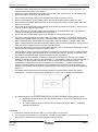
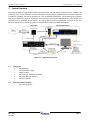
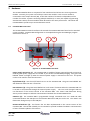
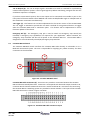
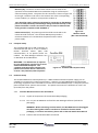
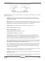
® CereStim R96 User Manual Blackrock Microsystems, LLC 391 Chipeta Way, Suite G Salt Lake City, UT 84108 Tel: (866) 806-3692 www.blackrockmicro.com Blackrock Microsystems CereStim R96 - User Manual © Copyright 2011 Blackrock Micosystems, LLC. All rights reserved. Copying or other reproduction of this document is prohibited without prior written consent of Blackrock Microsystems, LLC. Rev. 1.00 LB-0432 ® Page i Blackrock Microsystems CereStim R96 - User Manual Contraindications, Warnings and Cautions IEC60101-0102 Danger of Electrostatic Discharge (ESD) IEC 348 Consult instructions for use ISO7000-0434 Attention, consult accompanying documents IEC606417-5335 Type BF Applied Part IEC60417-5172 Class II Equipment EN-980 Combined Manufacturer/Manufacturing Date EN-980 Serial Number YEAR Contraindications The CereStim R96 should not be used in clinical applications. The CereStim R96 is intended for animal research applications only. The CereStim R96 should not be used in chronic applications. The CereStim R96 is intended for acute (<30 days) operation only. Electrocautery should not be performed while the CereStim R96 is in use. The CereStim R96 should not be used if the device has been dropped. Dropping the device may cause damage to internal components that affect system performance and safety. A dropped device must be returned to Blackrock Microsystems for inspection and recalibration before it can be used again (See Section 6 and 7 of the CereStim R96 User Manual). The CereStim R96 should not be used with any computer that has not been tested to the IEC 60950 standards. Warnings The CereStim R96 must only be used by medically trained and highly qualified personnel. This manual is to be used in support of device use by personnel who have received device training from Blackrock Microsystems. The CereStim R96 stimulation parameters should only be used within the safe operating range of the specific electrode being used. Use only the supplied CereStim R96 components (i.e. External Power Supply). Substitution of components not supplied by Blackrock Microsystems may affect system performance and safety. The CereStim R96 should be disconnected from the Stimulation System during defibrillation. The CereStim R96 is not defibrillator proof. Do not use the CereStim R96 in the presence of flammable anesthetic agents. Only connect CereStim R96 components to properly tested, grounded and dedicated AC outlets to reduce the risk of electrical shock. Do not use an adapter for ungrounded wall outlets. Do not use damaged components (i.e. cables, external power supply). Damaged components may compromise subject safety. Do not connect the CereStim R96 to an outlet controlled by a wall switch. Rev. 1.00 LB-0432 ® Page ii Blackrock Microsystems CereStim R96 - User Manual Avoid strong static discharges from sources like televisions or computer monitors because it can damage the electrical parts of the system. Keep the CereStim R96 away from liquids. Contact with water, shower spray, or wet surfaces can lead to the subject receiving an electrical shock. Do not unplug the power supply to the CereStim R96 while the system is in use. Do not connect/disconnect any cables to/from the CereStim R96 while the system is in use. Do not leave the CereStim R96 connected to the microelectrode array(s) or Stim Switch when the system is not in use. Do not change CereStim R96 Output Voltage values while connected to the subject. Doing so may result in an electric shock to the subject. When connecting the CereStim R96 to the Stim Switch or microelectrode array(s), use caution to minimize the likelihood of Electrostatic Discharge (ESD). Ensure that the CereStim R96 is securely positioned on a flat surface during use. Use caution when placing power cords, cables, and other connectors to minimize the likelihood of tripping or accidentally pulling on cables. Damaged cables may result in failed ground connections. Each component of the system must be plugged into a separate outlet (i.e. CereStim R96, Stim Switch, subcomponents of the data acquisition and any other accessory equipment). Using a powerstrip may cause leakage currents to exceed acceptable limits. Connecting equipment to and from the CereStim R96 may result in a summation of leakage currents that can lead to the subject receiving an electric shock. Care should be used in selecting equipment for connection to the Monitor port as it could potentially transmit large voltage transients directly to the microelectrode array(s). Devices connected to this port must be isolated from earth ground in compliance with IEC 60601-1. Risk of Electrical Shock Hazard: Accessory equipment connected to the SIP/SOP port must be certified according to the respective IEC standards, i.e., IEC 60950 for data processing equipment or IEC 60601-1 for electromedical equipment in order to reduce the risk of electrical shock. All combinations of equipment must be in compliance with IEC 60601-1-1 systems requirements. Anyone connecting additional equipment to the SIP/SOP port configures a medical system, and therefore is responsible that the system complies with the requirements of the system standard IEC 60601-1-1. IEC 60950 approved Information Technology Equipment must be placed outside the “patient environment.” The patient environment is defined as an area 1.5m (4.92 feet) from the patient. The following options are recommended if there is a need to remediate system leakage current: Redundant protective earth connection shall be made to either the medical device or the other equipment. The other equipment shall be powered from a medical grade (IEC 60601-1 compliant) separating transformer. Cautions Federal law restricts this device to sale, by or on the order of a physician. The CereStim R96 is ONLY recommended for use with low impedance (<100 kΩ) electrodes such as the NeuroPort SIROF array provided by Blackrock Microsystems. Rev. 3.00 LB-0314 ® Page iv Blackrock Microsystems CereStim R96 - User Manual Electromagnetic Compatibility The following tables document compliance levels and guidance from the IEC 60601-1-2 2007 Standard, for the electromagnetic environment in which the CereStim R96 should be used. Medical Electrical Equipment requires special precautions regarding EMC and should be installed and put into service according to the guidelines provided in the tables below. Guidance and Manufacturer’s Declaration – Electromagnetic Emissions The CereStim R96 is intended for use in the electromagnetic environment specified below. The customer or the user of the CereStim R96 should assure that it is used in such an environment Emissions Test Compliance Electromagnetic Environment - Guidance The CereStim R96 uses RF energy only for its internal RF Emissions function. Therefore, its RF emissions are very low and Group 1 CISPR 11 are not likely to cause any interference in nearby electronic equipment. RF Emissions The CereStim R96 is suitable for use in all Class A CISRP 11 establishments other than domestic establishments and those directly connected to the public low-voltage Harmonic Emissions Not Applicable power supply network that supplies buildings used for IEC 61000-3-2 domestic purposes. Voltage Fluctuations/ Flicker Emissions Not Applicable IEC 61000-3-3 Guidance and Manufacturer’s Declaration – Electromagnetic Immunity The CereStim R96 is intended for use in the electromagnetic environment specified below. The customer or the user of the CereStim R96 should assure that it is used in such an environment Electromagnetic Environment Immunity Test IEC 60601 Test Level Compliance Level Guidance Floors should be wood, Electrostatic concrete or ceramic tile. If Discharge (ESD) ±6kV Contact Not Applicable floors are covered with ±8kV Air synthetic material, the relative IEC 61000-4-2 humidity should be at least 30%. Electrical Fast Transient/Burst IEC 61000-4-4 Surge ± 2kV for power supply lines ±2 kV for input/output Lines ±1kV line(s) to line(s) ±2kV line(s) to earth ± 2kV for power supply lines ±2 kV for input/output Lines Not Applicable IEC 61000-4-5 Voltage dips, short interruptions and voltage variations on power supply input lines IEC 61000-4-11 Rev. 2.00 LB-0314 <5% UT (>95% dip in UT) for 0.5 cycle 40% UT (60% dip in UT) for 5 cycles 70% UT (30% dip in UT) Not Applicable Mains power quality should be that of a typical commercial or hospital environment. Mains power quality should be that of a typical commercial or hospital environment. Mains power quality should be that of a typical commercial or hospital environment. If the user of the CereStim R96 requires continued operation during power mains interruptions, it is recommended that the Page iv Blackrock Microsystems CereStim R96 - User Manual Guidance and Manufacturer’s Declaration – Electromagnetic Immunity for 25 cycles CereStim R96 be powered from <5% UT an uninterruptible power (>95% dip in UT) for 5 supply or a battery. sec It may be necessary to position the CereStim R96 further from Power Frequency sources of power frequency (50/60 Hz) magnetic magnetic fields or to install 3 A/m field Not Applicable magnetic shielding. The power frequency magnetic field IEC 61000-4-8 should be measured in the intended installation location to assure that it is sufficiently low. Guidance and Manufacturer’s Declaration – Electromagnetic Immunity The CereStim R96 is intended for use in the electromagnetic environment specified below. The customer or the user of the CereStim R96 should assure that it is used in such an environment Electromagnetic Environment Immunity Test IEC 60601 Test Level Compliance Level Guidance Portable and mobile RF communications equipment should be used no closer to any part of the CereStim R96 including cables, than the recommended separation distance calculated from the equation applicable to the frequency of the transmitter. Recommended Separation Distance Conducted RF IEC 61000-4-6 Radiated RF IEC 61000-4-3 3V 150kHz – 80MHz 80%am** 3V/m 80-2500 MHz 80%am** 3V d = 1,2√P 150kHz to 80MHz 3V/m d = 1,2√P 80MHz to 800MHz d = 2,3√P 800MHz to 2.5GHz Where P is the maximum output power rating of the transmitter in watts (W) according to the transmitter manufacturer and d is the recommended separation distance in meters (m). Field strengths from fixed RF transmitters, as determined by Rev. 1.00 LB-0432 ® Page v Blackrock Microsystems CereStim R96 - User Manual Guidance and Manufacturer’s Declaration – Electromagnetic Immunity an electromagnetic site survey a , should be less than the compliance level in each frequency range. b Interference may occur in the vicinity of equipment marked with the following symbol: ** Modulation scheme can be 2 Hz or 1 kHz. NOTE 1 At 80 MHz and 800 MHz, the higher frequency range applies NOTE 2 These guidelines may not apply in all situations. Electromagnetic propagation is affected by absorption and reflection from structures, objects and people. a Field strengths from fixed transmitters, such as base stations for radio (cellular/cordless) telephones and land mobile radios, amateur radio, AM and FM radio broadcast and TV broadcast cannot be predicted theoretically with accuracy. To assess the electromagnetic environment due to fixed RF transmitters, an electromagnetic site survey should be considered. If the measured field strength in the location in which the CereStim R96 is used exceeds the applicable RF compliance level above, the CereStim R96 should be observed to verify normal operation. If abnormal performance is observed, additional measures may be necessary, such as re-orienting or relocating the CereStim R96. b Over the frequency range 150 kHz to 80 MHz, field strength should be less than 3 V/m Rev. 1.00 LB-0432 ® Page vi Blackrock Microsystems CereStim R96 - User Manual System Specifications Model Name CereStim R96 Number of Output Channels 96 Number of Current Modules 16 Type of Protection Class II Degree of Protection Type BF Applied Part Output Current 1-215 µA, adjustable in 1 µA increments Maximum Output Voltage ±4.7V to ±9.5V, adjustable in 0.6V increments Train Duration 194µs-66,845,700µs (0.000194 – 66.8 seconds) 1-255 pulses/train Pulse Duration 141µs – 196,605µs (0.000141 – 0.196605 seconds) Anodic Pulse Duration: 44-65,535µs/phase Cathodic Pulse Duration: 44-65,535µs/phase Adjustable in 1µs increments Recommended Electrode Impedance <100 kΩ PC Hardware Interface USB A-B cable Stim Manager PC Software Windows XP (32-bit), Windows 7 (32-bit or 64-bit) Compatibility Rev. 1.00 LB-0432 Analog Resolution 12 bits Slew Rate 550 V/µs External Power Supply PMP15M-13 Protek Power Supply AC Input: 100-240Vac, 0.5-0.3A, 50-60Hz (The system was only evaluated to 120V, 60Hz) DC Output: 15V, 1A MAX Emergency Off Switch ¼” Mono Phone Plug Normally Closed Switch with < 10Ω on resistance recommended. CereStim R96 Cable Connectors 40 pin shrouded header; 2.54mm pitch Manufacturer: Assman Electronics/AWH40G-0222-T-R Monitor Connector 10 pin dual row header; 2.56mm pitch Manufacturer: Samtec/SSQ-110-01-G-D IPX Rating Ordinary Equipment, Not Fluid Resistant, IP20 Operating Environment 10˚C to 40˚C, 10 to 85% R.H. (non-condensing) Storage/Transportation Environment -15˚C to 60˚C, 10 to 85% R.H. (non-condensing), 500 to 1060 hPA ® Page vii Blackrock Microsystems CereStim R96 - User Manual Table of Contents Warnings ....................................................................................................................................... i 1 System Overview ........................................................................................................................... 1 1.1 Packing List ........................................................................................................................................... 1 1.2 Accessories (Not Included) ................................................................................................................... 1 2 Hardware....................................................................................................................................... 2 2.1 CereStim R96 Front Panel..................................................................................................................... 2 2.2 CereStim R96 Back Panel ...................................................................................................................... 3 2.3 Computer Setup ................................................................................................................................... 4 2.4 Hardware Setup .................................................................................................................................... 4 2.4.1 CereStim R96 Connection to the Stim Switch.............................................................................. 4 2.4.2 CereStim R96 Connection to Electrodes ...................................................................................... 5 3 Stim Manager Software.................................................................................................................. 6 3.1 Stim Manager Configuration Tab ......................................................................................................... 6 3.2 Stim Manager Report Tab .................................................................................................................. 11 3.3 Stim Manager Administration Tab ..................................................................................................... 12 3.4 Saving and Exporting Information ...................................................................................................... 13 3.5 Application Programming Interface (API)........................................................................................... 13 4 Device Care and Storage ............................................................................................................... 13 5 Troubleshooting........................................................................................................................... 13 6 Warranty ..................................................................................................................................... 14 7 Return Merchandise Authorization ............................................................................................... 14 Appendix A: ......................................................................................................................................... 15 List of Figures Figure 1-1: Application Overview ............................................................................................................ 1 Figure 2-2: CereStim R96 Front Panel ...................................................................................................... 2 Figure 2-3: CereStim R96 Back Panel ....................................................................................................... 3 Figure 2-4: CereStim R96 Cable Connector Layout ................................................................................... 3 Figure 2-5: Monitor Pinout ..................................................................................................................... 4 Figure 2-6: CereStim R96 Computer Setup............................................................................................... 4 Figure 3-7: Stim Manager Main Window ................................................................................................. 6 Figure 3-8: Test Pulse ............................................................................................................................. 7 Figure 3-9: Cathodic and Anodic Pulse Figures ......................................................................................... 8 Figure 3-10: Stimulation Script Window .................................................................................................. 9 Figure 3-11: Stim Manager Report Tab .................................................................................................. 11 Figure 3-12: Stim Manager Administration Tab ..................................................................................... 12 Rev. 1.00 LB-0432 ® Page viii Blackrock Microsystems 1 CereStim R96 - User Manual System Overview The CereStim R96 is a fully programmable neurostimulator with 96 output channels and the capability of producing up to 16 simultaneous stimuli. The biphasic current pulses generated by the CereStim R96 are intended to stimulate neurons in proximity to a set of implanted electrodes. By interfacing the CereStim R96 with a switching system for stimulation and recording, the CereStim R96 becomes a very flexible and powerful tool for analyzing neural signals. The figure below shows an application overview of how the CereStim R96 fits into a switching system for stimulation and data acquisition applications. Figure 1-1: Application Overview 1.1 Packing List 1 CereStim R96 1 External Power Supply 1 USB A-B Cable 1 Stim Manager Software CD-ROM 1 CereStim R96 User Manual 1 CereStim R96 API 1.2 Accessories (Not Included) 1 Stim Switch System Rev. 1.00 LB-0432 ® Page 1 Blackrock Microsystems 2 CereStim R96 - User Manual Hardware The CereStim R96 hardware is composed of one main board and at least one current generator module. Currently, the system can hold up to 16 current modules. Each current module is connected to each output channel (96), so that the number of channels is independent of the number of modules. Systems containing multiple modules (2 or more) are capable of generating simultaneous stimuli, where N modules allow N stimuli at the same precise time. This allows the CereStim R96 to produce up to 16 simultaneous stimuli. 2.1 CereStim R96 Front Panel The CereStim R96 Front Panel interfaces the PC with the CereStim R96 main board and its attached current modules. CereStim R96 configuration is accomplished using the Stim Manager program described in Section 3. 2 6 7 8 4 1 3 5 Figure 2-2: CereStim R96 Front Panel Power Supply Connector (1): The CereStim R96 is capable of being powered through an external, medical grade power supply that is included as part of the CereStim R96 packaging. The green LED labelled ‘Power’ will light up when the external power supply is connected to the unit. The power cord is to be used for mains disconnection. On/Off Switch (2): Use the on/off switch to turn on the CereStim R96. The green LED labelled ‘On’ will illuminate when the unit is turned on. LED Indicators (3): The green LEDs labelled ‘On’ and ‘Power’ illuminate when the CereStim R96 unit is turned on and powered through the external power supply. The ‘Low’ and ‘Charged’ LEDs are non-functional in the current version of the CereStim R96. The ‘Status’ LED illuminates during activity on the USB port to indicate communication between the CereStim R96 and PC. USB Port (4): The CereStim R96 is programmed through commands sent via a USB A-B cable connected between the USB port on the CereStim R96 and a USB port on the PC. The ‘Status’ LED illuminates during activity on the USB port. RS-232 Isolated Port (5): This feature has not been implemented in the current version of the CereStim R96. The RS-232 isolated port is intended to provide hardware-hardware communication in future firmware updates of the device. Rev. 1.00 LB-0432 ® Page 2 Blackrock Microsystems CereStim R96 - User Manual TTL 5V Output (6): The TTL 5V output signal is intended to be used as a method for synchronizing external data acquisition systems. The TTL goes high 60 µs before stimulating, and goes low once the stimulation sequence is complete. If you have a Stim Switch System, the TTL 5V output can be connected to an Enable In port on the front panel of the Stim Switch Control Module and used to enable/disable single or multiple banks of the stimulation connections simultaneously. TTL Trigger (7): This feature has not been implemented in the current version of the CereStim R96. The TTL Trigger is intended to provide the user with a method for using external devices to trigger when the CereStim R96 sends a stimulation pulse. This feature will be implemented in future firmware updates of the device. Emergency Off (8): The emergency stop jack is used to attach an emergency stop switch (not included) if emergency stop capabilities are required for your application. When activated, the emergency stop controller will shut off all power to the CereStim R96 unit. The CereStim R96 is designed for use with Normally Closed (NC) Emergency Stop Switches. 2.2 CereStim R96 Back Panel The CereStim R96 Back Panel interfaces the CereStim R96 either directly to electrodes or to a Blackrock Stim Switch system. The user is responsible for supplying any cables necessary for direct connection to the electrodes. 9 11 10 Figure 2-3: CereStim R96 Back Panel CereStim R96 Cable Connectors (9): Connectors A-C provide a connection between the CereStim R96 and the Stim Switch/Electrodes. Connector A corresponds with electrode output channels 1-32, connector B with channels 33-64 and connector C with channels 65-96. Instructions for connecting the CereStim R96 to a Switching System are provided in Section 4 below. The layout of the CereStim R96 Cable Connector is shown in Figure 2-4 below. Figure 2-4: CereStim R96 Cable Connector Layout Rev. 1.00 LB-0432 ® Page 3 Blackrock Microsystems CereStim R96 - User Manual Monitor (10): Connection to the monitor allows users to observe the operation of the CereStim R96 Current Modules using an oscilloscope or other monitoring device. The pinout for this connector is shown in Figure 2-5 to the right. Numbers 1-16 refer to the monitor line of the corresponding current module (i.e. number 1 corresponds to module 1). Care should be used in selecting equipment for connection to the Monitor port as it could potentially transmit large voltage transients directly to the patient electrodes. Devices connected to this port must be isolated from earth ground in compliance with IEC 60601-1. Patient Ground (11): The patient ground should be connected to the Patient Ground connector. The CereStim R96 System provides a minimum isolation of 2.5 kV between the patient and the mains power supply. 2.3 Figure 2-5: Monitor Pinout (NC = Not Connected) Computer Setup The CereStim R96 uses a USB connection to communicate with the PC. It uses a standard Human Interface Device (HID) USB communication, so no specific drivers are needed. The Stim Manager Software runs on Windows XP and Windows 7. WARNING: The Stim Switch (if required for your application) should only be used with an IEC 60950 Computer. The computer must be placed outside of the patient environment which is defined as an area 1.5m (4.92 feet) from the patient 2.4 Figure 2-6: CereStim R96 Computer Setup Hardware Setup The CereStim R96 and its subcomponents (i.e. USB A-B Cable and external power supply) are all suitable for use within the “patient environment.” However, any IEC 60950 approved information technology equipment that is intended for use with the CereStim R96 System (i.e. computer) must be placed outside of the “patient environment.” The patient environment is defined as an area 1.5m (4.92 feet) from the patient. 2.4.1 CereStim R96 Connection to the Stim Switch 2.4.1.1 Unpack all components of the CereStim R96 packaging. 2.4.1.2 Turn on your IEC 60950 PC and load the Stim Manager Software (included in packaging). WARNING: When connecting to a Stim Switch, the IEC 60950 PC must be plugged into the medical grade isolation transformer included in the Stim Switch packaging. For further instructions, please refer to the Stim Switch User Manual 2.4.1.3 Confirm that the CereStim R96 is turned off. Rev. 1.00 LB-0432 ® Page 4 Blackrock Microsystems CereStim R96 - User Manual WARNING: Always make sure that the CereStim R96 is turned off before connecting/disconnecting any cables 2.4.1.4 Connect the external power supply to the CereStim R96 and plug it into a wall outlet. 2.4.1.5 Connect the USB port on the Front Panel of the CereStim R96 to a USB port on the computer with the USB A-B cable (included in packaging). 2.4.1.6 Connect the appropriate end of the CereStim R96 Interconnection Cables to the CereStim R96 cable connectors labelled A-C on the back panel of the CereStim R96. These connections are keyed and lock the cables in place when connected appropriately. 2.4.1.7 Connect the opposite end of the cables to the ‘STIM IN’ Connectors on the front panel of the Stim Switch Control Module. Secure each connector in place using two thumbscrews (provided in Stim Switch packaging). Please refer to the Stim Switch User Manual for further instructions regarding the use of this system. 2.4.1.8 Open the Stim Manager Software on your PC and turn on the CereStim R96. The status bar in the lower right-hand corner of the Stim Manager window should change from green to orange, indicating that the CereStim R96 is connected. Refer to Section 3 below for further instructions regarding the use of the Stim Manager Software. WARNING: The CereStim R96 must be turned off when not in use. 2.4.2 CereStim R96 Connection to Electrodes For customer supplied connections, connection to the CereStim R96 is as follows: 2.4.2.1 Unpack all components of the CereStim R96 packaging. 2.4.2.2 Turn on your IEC 60950 PC and load the Stim Manager Software (included in packaging). 2.4.2.3 Confirm that the CereStim R96 is turned off. WARNING: Always make sure that the CereStim R96 is turned off before connecting/disconnecting any cables 2.4.2.4 Connect the external power supply to the CereStim R96 and plug it into a wall outlet 2.4.2.5 Connect the USB port on the Front Panel of the CereStim R96 to a USB port on the computer with the USB A-B cable (included in packaging). 2.4.2.6 Connect one end of the customer supplied cables to the CereStim R96 Cable Connectors on the Back Panel of the CereStim R96. Connect the other end of the cables directly to the connectors on the patient electrodes. Refer to Figure 2-4 for a pinout of the locking connector on the CereStim R96. Rev. 1.00 LB-0432 ® Page 5 Blackrock Microsystems CereStim R96 - User Manual CAUTION: The CereStim R96 is ONLY recommended for use with low impedance (<100 kΩ) electrodes such as the NeuroPort™ SIROF array provided by Blackrock Microsystems 2.4.2.7 Open the Stim Manager Software on your PC and turn on the CereStim R96. The status bar in the lower right-hand corner of the Stim Manager window should change from green to orange, indicating that the CereStim R96 is connected. Refer to Section 3 below for further instructions regarding the use of the Stim Manager Software. 3 Stim Manager Software The parameters of the biphasic current pulses output by the stimulator can be altered in the Stim Manager Software and updated to the CereStim R96 via a USB A-B cable. The Stim Manager main window is shown in Figure 3-6 below. 3.1 Stim Manager Configuration Tab 5 9 2 3 6 4 7 8 10 1 Figure 3-7: Stim Manager Main Window Status Bar (1): The status bar can be in one of the three following states: CereStim R96 is not connected CereStim R96 is connected Stimulating… If the CereStim R96 unit is on and the USB cable is connected, the status bar should change from green to orange. The CereStim R96 must be powered on in order for the software to recognize the connection. Modules Array Panel (2): Once the CereStim R96 has been connected and recognized by the Stim Manager Software, the available current modules are highlighted green in the Modules Array Panel. All unavailable Rev. 1.00 LB-0432 ® Page 6 Blackrock Microsystems CereStim R96 - User Manual modules are grey. Active current modules can be disabled by clicking on one of the active arrays. Deactivated modules change from green to red. Enabled Disabled Unavailable Mode Panel (3): Stim Manager has two working modes: automatic and manual. The mode is changed by clicking the ‘Switch’ button in the Mode Panel. Auto Mode: This is the default mode. Stim Manager must be in Auto Mode in order to create a new pulse configuration or make any changes to existing pulse configurations. Auto mode allows the user to create complex stimulation scripts as well as repetitive cycles. Manual Mode: This mode is intended for single stimulation applications. In this mode, the user selects an electrode channel from the Electrode Array Panel and a Pulse Configuration from the Configuration ID Panel. Click ‘Start’ to send the selected pulse to the selected electrode channel. Stimulation scripts are not available in this mode. Electrode Array Panel (4): In Auto Mode, selecting an electrode channel from this panel will disable that channel, turning the channel from green to red. The channel can be re-enabled by clicking on that channel a second time. In Manual Mode, clicking on an electrode channel will select it for stimulation, turning the channel from green to yellow. If the electrode channel is unavailable, the channel appears grey. Test Modules: The CereStim R96 has an auto-check function called Test Modules. When the Test Modules button is selected, the system sends a pulse (Config 0) to an internal 100KΩ resistor and measures the output voltage at five different points of the test pulse (Figure 3-9). If the output voltages are in line with the parameters of the current pulse, then the module is “OK.” If not, Stim manager provides the following message: “ERROR. Possible voltage limitation. Please check it.” Figure 3-8: Test Pulse Test Electrodes: Clicking the Test Electrodes button sends a stimulus (config 0) to each of the enabled electrodes and measures the output voltages (V) at five different points of the pulse (same as Test Modules). These values, along with an estimation of the impedance values (KΩ) for each electrode channel, are provided in the Log Window of the Report Tab. The impedance measurements offer the user a tool for detecting broken electrodes or gradual degradation. During this test, the system also checks the second voltage point of the pulse to determine if it’s close to the Output Vmax. If so, the message “HIGH IMPEDANCE. Possible voltage limitation” appears, and the user should adjust the Output Vmax value or re-evaluate the stimulation parameters. In addition to the log window, the results are saved in a file named: “/Measurements/CereStim R96_ddmmyy_hhmmss.txt”. These files are tabulated for easy importation into a database Pulse Figure: This feature identifies each parameter of the stimulation pulse with a red circle as the user moves the mouse over the corresponding parameter boxes in the Stimulus Panel. The pulse figure also identifies whether the first phase of the selected stimulus from the Configuration ID Panel is anodic or cathodic. Rev. 1.00 LB-0432 ® Page 7 Blackrock Microsystems CereStim R96 - User Manual Anodic First Cathodic First Figure 3-9: Cathodic and Anodic Pulse Figures Pulses Panel (5): This panel allows the user to define up to 16 different stimulation patterns. The available features are as follows: Config Id: This drop down box allows the user to select an identification number for up to 16 different pulse configurations. Config 0 is used in the Test Modules and Test Electrodes functions and should not be changed. Wave Form: The user can set the stimulator to generate either the Anodic or Cathodic phase of the biphasic pulse first. The pulse figure in the lower left-hand corner of the Stim Manager Window indicates whether a selected pulse configuration is ‘anodic first’ or ‘cathodic first.’ Number of Pulses: 1-255 biphasic pulses are available for each Configuration ID. Range of Interpulse Delay: 53-65,535 µs Range of Interphase Delay: 53-65,535 µs Range of Amplitudes (Phase I & Phase II): 1-215 µA Phase Width (Phase I & Phase II): 44-65,535 µs Fast Discharge: The nature of the CereStim R96 implies that there may be some undesirable effects in the output waveform. The Fast Discharge parameter enables a 100 Ω resistor at the generator output that removes any undesirable effects and cleans up the waveform. NOTE: The user should analyze the possible consequences of enabling this option in experiments. Add: After defining the parameters of the pulse, click ‘Add’ to add the new pulse configuration to the Configuration ID Panel (4). All new pulse configurations created by the user must be added to the Configuration ID Panel before the user can begin stimulating. NOTE: Stim Manager enforces balanced charge in the biphasic pulse configurations created by the user. In the event that the user creates a pulse with an unbalanced charge, the software will produce an error message notifying the user that the parameters of the biphasic pulse must be modified to balance the charge. Remove: In order to remove a pulse configuration from the Configuration ID Panel (4), click on the Configuration ID number that is to be deleted and click the ‘Remove’ button. Remove All: This feature allows the user to delete all pulse configurations in the Configuration ID Panel at the same time. Hz: This box reports the frequency (Hz) of the pulse configuration based on the user inputs for the interpulse delay, interphase delay, width of phase I and width of phase II. Rev. 1.00 LB-0432 ® Page 8 Blackrock Microsystems CereStim R96 - User Manual Configuration ID Panel: This panel stores the pulse configurations created by the user in the Pulses Panel. The test pulse parameters are saved as Config 0 and should not be changed. Stimulation Panels (6): Stimulation scripts are defined by a series of single stimulations, groups and wait instructions. Stimulus Panel: This feature is available when Stim Manager is set to Auto Mode. It allows the user to select an electrode channel (1-96) and assign it to an electrode configuration from the Configuration ID Panel. By clicking ‘Add,’ the electrode channel and electrode configuration pairs are added to the Stimulation Script. Group Definition Panel: Groups allow the user to generate stimuli from different current modules at the same time. There are four basic rules for groups: A group must have both begin and end instructions A group can’t have more stimuli than enabled current modules An electrode can’t be used more than once in the same group Wait instructions cannot be used within a group By clicking ‘Add,’ the command to begin or end a group is added to the Stimulation Script. Wait Instruction Panel: Wait instructions allow the user to introduce delays in milliseconds to the stimulation script. Delays can be added before or after any single stimulus or group. This command is recommended for long delays. Short delays can be implemented using the Interpulse delay defined in the pulse configuration. By clicking ‘Add,’ the wait instruction is added to the Stimulation Script. Stimulation Script Window (7): This window allows the user to view the stored sequence of stimulation events added from the Stimulus, Group Definition and Wait Instruction Panels. Stimulation is sequential for single stimuli and simultaneous for stimuli within a group. The maximum number of commands in a sequence is 128. Stimulation Script Commands (8): These command buttons begin, end, pause and make adjustments to the Stimulation Script. Remove: By clicking this button, the user is able to remove any single line in the Stimulation Script. Remove All: By clicking this button, the user is able to clear the Stimulation Script. Pre-Process: Once a Stimulation Script has been created, the PreFigure 3-10: Stimulation Process button must be selected prior to stimulation in order to: Script Send the pulse configurations to the available current modules within the CereStim R96 unit. Check for correct syntax of the groups in the Stimulation Script. Assign a current module to each stimulus. Send the Stimulation Script to the CereStim R96 motherboard. Calculate the total elapsed time for the Stimulation Script (recorded in the Log Window). Timing measurements depend on the pulse configurations and internal hardware delays. The internal hardware delays are as follows: Rev. 1.00 LB-0432 ® Page 9 Blackrock Microsystems o o o o CereStim R96 - User Manual 68 µs delay between single stimulations 76 µs delay between the end of a stimulus and the beginning of a group 68 µs delay between the end of a group and the beginning of another stimulus 116 µs delay between the end of a group and the beginning of another group. Repetition Panel: This feature allows the user to repeat the Stimulation Script a specified number of times, or to run it as a continuous loop. Without a defined number of repetitions, the CereStim R96 defaults to a single pass of the Stimulation Script. In a continuous loop, the CereStim R96 requires a manual stop in order to end stimulation. Start: Once Pre-Process has been completed, the system is ready to stimulate. Stimulation is initiated by clicking the Start button. Pause: Clicking this button immediately pauses the Stimulation Script. To resume stimulation from the same point in the Script, click the Start button. Stop: Clicking this button manually stops the stimulation. It is not possible to modify any parameter during stimulation. The user must stop the stimulation sequence prior to making any changes to the Stimulation Script or Pulse configurations. After making changes, the Pre-Process button must be pressed again in order to update the changes to the CereStim R96. Output Vmax Panel (9): This feature allows the user to select the maximum analog output voltage as a safety measure for stimulation. Users should be cautious when making changes to the Output Vmax. A low Vmax may provide more safety, but it may also distort higher voltage output signals, either because the current is too high or the impedance is too high. Drop-down Menu: The user can select maximum output voltages ranging from ±4.7V to ±9.5V (0.6V) from the drop-down menu. Update: Clicking the Update button updates any changes to the Output Vmax in the hardware. Read: Clicking the Read button will return the measured analog voltage active in the system. WARNING: Do not change CereStim R96 Output Vmax values while connected to the patient. Doing so may result in an electric shock to the patient. Log Window (10): The Log Window echoes commands sent from the Stim Manager Software to the CereStim R96, provides updates on the connection status between the CereStim R96 and the PC, and indicates any discrepancies in the Pulse Configurations or Stimulation Script. It also provides the user with results from the Test Modules and Test Electrodes functions. Rev. 1.00 LB-0432 ® Page 10 Blackrock Microsystems 3.2 CereStim R96 - User Manual Stim Manager Report Tab 1 2 4 3 Figure 3-11: Stim Manager Report Tab Researcher Panel (1): This feature allows the user to record and save the name of the researcher conducting the test/procedure. Patient Panel (2): This panel allows the user to record and save identifying information for the patient, including the patient’s name and pathology as well as the date and time of the test/procedure. Comments Panel (3): This panel allows the user to record and save comments or observations noted during the test/procedure. Log Window (4): This panel provides an extended view of the Log Window. The Log Window echoes commands sent from the software to the CereStim R96, provides updates on the connection status of the CereStim R96 and indicates any discrepancies in the Pulse configurations or Stimulation Scripts defined by the user. It also provides the user with results from the Test Modules and Test Electrodes functions. Rev. 1.00 LB-0432 ® Page 11 Blackrock Microsystems 3.3 CereStim R96 - User Manual Stim Manager Administration Tab 1 2 3 Figure 3-12: Stim Manager Administration Tab Unlock Administrator Rights Panel (1): Unlocking the Administrator Rights allows users to restrict the Output Vmax, Amplitude, Phase Width, Interphase Delay, Interpulse Delay and Charge per Phase to a set of maximum values. Upon initial start-up, the administrator password is set to ‘Stim100.’ After unlocking the administrator rights, the user can change this password in the ‘Change Password’ panel. Unlock: After entering the appropriate password, click the ‘Unlock’ button to gain Administrative Rights. Lock: After any settings are changed, click the ‘Lock’ button to store the changes and prevent other users from making adjustments to the settings. Max Values Panel (2): Only users with Administrative Rights are able to make adjustments to the maximum allowable values for the Output Vmax, Amplitude, Phase Width, Interphase Delay, Interpulse Delay and Charge per Phase. When making changes to the Max Values, administrative users must specify all max values in order for Stim Manager to accept the update. Upon initial start-up, the default Max Values are as follows: Max Output Voltage: 6.5V Max Amplitude: 100µA Max Width: 300µs Max Interphase: 300µs Max Interpulse: 300µs Max Charge per Phase: 30,000pC Rev. 1.00 LB-0432 ® Page 12 Blackrock Microsystems CereStim R96 - User Manual Update: New max values are stored by clicking the ‘Update’ button. This button is only available to users with administrative rights. Read: All users are able to read the existing Max Value settings by clicking the ‘Read’ button regardless of administrative rights. Change Password Panel (3): After unlocking Administrator Rights, users can change an existing password to a new password by entering the old password into the ‘Enter Old Password’ box, entering the new password in the ‘Enter New Password’ box and retyping the new password in the ‘Confirm New Password’ box. New passwords must not be more than 32 characters. Change Password: Click the ‘Change Password’ button to apply changes to the password. 3.4 Saving and Exporting Information Stim Manager is able to save any changes the user makes in the software environment, including: activated and deactivated current modules, test electrodes results, pulse configurations, stimulation scripts, and reports. Stim Manager is then able to export any of that information as a text file. The default roots are: Environment files: Test electrodes result: System advanced configurations: 3.5 [application folder]/Documents/ [application folder]/Measurements/ [application folder]/SystemFiles/ Application Programming Interface (API) For customers who want to control the CereStim R96 via proprietary software, a complete API is made available. Please refer to the CereStim R96 API User Manual included in the CereStim R96 packaging for further information. 4 Device Care and Storage 5 Handle the CereStim R96 with care. Do not drop or strike the device. In the event that the device is dropped, the CereStim R96 must be returned to Blackrock Microsystems for inspection and recalibration before the device can be used again (See section 7). Clean the outside of the CereStim R96 using a cloth dampened with water or alcohol when necessary. Do not submerge the device in water or cleaning solutions. Keep the device away from liquids. The CereStim R96 is not fluid resistant and can become damaged by fluid ingress. Store the CereStim R96 at -20˚C to 50˚C, 10 to 100% relative humidity (non-condensing). Troubleshooting Stim Manager does not recognize the CereStim R96. I am unable to send commands from Stim Manager to the CereStim R96. 1. Make sure that your PC recognizes the CereStim R96 as an HID interface. Right Click on ‘My Computer’ in the Start-up Menu and select Manage. Select Device Manager, expand the Human Interface Devices List and confirm that your USB device is recognized. If the USB is not recognized, the CereStim R96 may require a shorter USB cable. 2. Check to make sure that all connections are secure. Rev. 1.00 LB-0432 ® Page 13 Blackrock Microsystems CereStim R96 - User Manual 3. If the problem persists, contact Blackrock Microsystems for additional troubleshooting or to initiate an RMA I am unable to make changes to the pulse configurations or the stimulation script. 1. Confirm that you are in Auto Mode. Stim Manager must be in Auto Mode in order to make any changes to the pulse configurations or the stimulation script. 2. Click the ‘Stop’ button. If you have just finished a stimulation sequence, you must press ‘Stop’ in order to make changes to the pulse configurations or the stimulation script. 3. If the problem persists, contact Blackrock Microsystems for additional troubleshooting or to initiate an RMA. 6 Warranty Blackrock Microsystems, Inc. warrants that its products are free from defects in materials and manufacturing for a period of one year from the date of shipment. Blackrock will, at its option, repair or replace any product that does not comply with this warranty. This warranty is voided by: 1. Any modification or attempted modification to the product done by anyone other than an authorized Blackrock employee 2. Any abuse, negligent handling or misapplication of the product. This constitutes the sole warranty made by Blackrock, Inc. There are no other warranties, expressed or implied, which extend beyond those described herein or to anyone other than the original purchaser, including the implied warranties of merchantability and fitness for a particular purpose. In no event shall Blackrock Microsystems, Inc. be liable for any incidental or consequential damages, or for the infringement of any patent rights or third party rights due to the use of its products. 7 Return Merchandise Authorization In the unlikely event that your system needs to be returned to Blackrock for repair or maintenance, do not send any equipment back without a Return Merchandise Authorization Number. An RMA number will be issued to you by a Blackrock representative. If you need to obtain an RMA number, you may contact a product support representative at (801) 582-5533 or toll free at (866) 806-3692. Once an RMA number has been issued, it is important to safely pack the returned item for shipping back to Blackrock. It is preferred that you save the original boxes and packing materials that your system arrived in for return shipment. Please address the package as follows: Blackrock Microsystems, Inc. ATTN: RMA# 391 Chipeta Way, Suite G Salt Lake City, UT 84108 USA Tel: (801) 582-5533 Rev. 1.00 LB-0432 ® Page 14 Blackrock Microsystems CereStim R96 - User Manual Appendix A: Observed Current at Increasing Output Vmax Appendix A provides indications for the amount of output current (µA) that is observed at each output Vmax voltage for either 99 kΩ or 49.9 kΩ electrode impedances. The figures below show the observed output current (µA) measured from the CereStim R96 electrode outputs for both the Cathodic and Anodic phases. These measurements are based on a set of input current values (µA) that were entered into the Stim Manager software. CereStim R96 output measurements were taken at each Output Vmax using both 99 kΩ and 49.9 kΩ electrode impedances. 99 kΩ Electrode Impedances Rev. 1.00 LB-0432 ® Page 15 Blackrock Microsystems Rev. 1.00 LB-0432 CereStim R96 - User Manual ® Page 16 Blackrock Microsystems Rev. 1.00 LB-0432 CereStim R96 - User Manual ® Page 17 Blackrock Microsystems CereStim R96 - User Manual 49.9 kΩ Electrode Impedances Rev. 1.00 LB-0432 ® Page 18 Blackrock Microsystems Rev. 1.00 LB-0432 CereStim R96 - User Manual ® Page 19 Blackrock Microsystems Rev. 1.00 LB-0432 CereStim R96 - User Manual ® Page 20 Blackrock Microsystems Rev. 1.00 LB-0432 CereStim R96 - User Manual ® Page 21 Blackrock Microsystems Rev. 1.00 LB-0432 CereStim R96 - User Manual ® Page 22