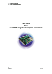
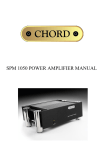
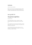
1
Red Standard CD Player 1 Contents Red Standard CD Player ...............................................................3 Product Description.......................................................................3 Inventory .......................................................................................3 When setting up.............................................................................4 Safety Warnings ............................................................................5 AC Power connection....................................................................6 AC Connector and Switch.............................................................6 Powering up...................................................................................6 Powering down - long-term...........................................................6 Powering down - short-term..........................................................6 Connecting your equipment ..........................................................7 Balanced analogue outputs............................................................8 Unbalanced analogue outputs........................................................8 Everyday use of your Red Standard..............................................9 Basic operation............................................................................10 Status display and function .........................................................11 CD Operation ..............................................................................13 Advanced functions.....................................................................14 Trigger Outputs ...........................................................................15 Product Specification ..................................................................16 2 Red Standard CD Player Thank you for buying a Chord Electronics product. Before you start to enjoy your CD player, please take a couple of minutes to read how to connect your audio equipment and loudspeakers and how to maximise your listening experience. Product Description The RED Standard CD player combines conventional CD playback with the addition of QBD76 conversion technology to give optimum performance at 44.1KHz sample frequencies. It is able to reproduce considerable clarity with the transient timings accurately reproduced via the 76 bit DSP core and 4096 tap digital WTA filter. Used as a standalone CD player or as a combined DAC and player, it is able to deliver benchmark CD reproduction and act as a digital to analogue converter for additional sources. Inventory As well as your Red Standard and this user manual, you should also have received the following items. 1. Red Standard remote control 2. Power cord 3. Chord guarantee registration card 3 When setting up To ensure that your Red Standard works efficiently and safely, please pay particular attention to the following issues. ventilation Your Red Standard should have at least 5cm of clear space all around it to ensure a free flow of air at all times. We do not recommend that you place Red Standard directly on a carpet. AC lead and plug All Chord equipment comes supplied with the correct power lead and plug. This should be used at all times. if you need to fit a plug for UK/Europe Connect the blue wire to the neutral terminal Connect the brown wire to the live terminal Connect the yellow/green wire to the earth terminal if you need to fit a plug for US/Canada Connect the white wire to the neutral terminal Connect the black wire to the live terminal Connect the green to the earth terminal earthing issues in Europe In some European countries a hum may occur if your Red Standard is connected to mains sockets that do not have an earth. If this is the case please ensure that: 1. Your transport is connected via a multi-way mains block, which contains an earth point at each socket outlet. This is to ensure that the chassis metalwork of each item is connected together. 2. We recommend that an earthing method for your building be implemented. 3. Use the connecting points on your Chord unit and connect to an available earth point. 4 Safety Warnings It is important that your Red Standard is earthed at all times via its own mains lead. Failure to do this may be hazardous. The power supply components within the transport are designed to operate at lethal voltages and energy levels. Circuit designs that embody these components conform to applicable safety requirements. Precautions must be taken to prevent accidental contact with power-line potentials. Do not connect grounded test equipment. Caution: This product employs a laser that emits both visible and invisible radiation. Removal of the top cover or tampering with any of the enclosed electronics may result in exposure to hazardous levels of laser radiation that could cause eye damage. To prevent injury this product should be returned for qualified service to Chord Electronics Ltd. There are no user serviceable parts within the Red Standard CD player. Unauthorised tampering or dismantling of this product will invalidate the warranty and could cause injury. 5 AC Power connection The AC power connector of Red Standard is at the back of the unit. Plug the female end (socket) of the power cord into the power connector of the transport, and the male end(plug) of the power cord into AC wall socket or AC extension socket. The Red Standard CD player features a universal voltage high frequency power supply and will operate automatically from 65V to 260V AC, 50 or 60Hz. For optimum operation it is recommended that the Red Standard is connected directly to the wall socket via the power cord provided. AC Power Switch AC Connector IEC 10A EARTH AC Connector and Switch Powering up Press the top of the power switch labelled ‘I’. Red Standard will now power up. The Red Standard features a dual display system showing both system status and disc information. The red multi function display will read ‘CHORD’ followed by the status information showing input, buffer, frequency settings and lock information. If Red Standard has no disc loaded, the top panel display with read “NO DISC”; if a disc has been loaded then the number of tracks and length of the CD will be shown. Please allow a short time for Red Standard to read the disc’s Table of Contents (TOC). During this time the display will indicate “-- ----“ Powering down - long-term 1. Press the STANDBY button on the remote to put Red Standard into STANDBY. 2. Press the right-hand side of the power switch labelled ‘O’. Powering down - short-term For everyday use there is no need to power Red Standard down completely. Press the STANDBY button on remote to put Red Standard into its Standby mode. The audio circuits remain active in this mode. 6 Connecting your equipment Right output RCA–phono XLR Left output XLR Right output AES/EBU Input Left output RCA-phono Optical Input Red Standard - rear panel connections All the input and output connections of Red Standard are situated on the rear panel of the transport. Red Standard has two types of digital input optical and AES/EBU and both balanced and unbalanced analogue outputs. Digital inputs The Red Standard comes equipped with two different types of digital inputs, allowing compatibility with virtually any digital audio source equipment. Digital audio source equipment includes CD transports, DVD players and Mini Disc players. The digital inputs consist of one AES balanced XLR input (XLR) and one Plastic Fibre Optical TOSLink input (OPT). These inputs can be selected via the I/P button on the front panel and will output analogue audio from both the balanced and unbalanced connections. AES/EBU Input 7 Optical Input Balanced analogue outputs You need to connect the analogue outputs on the back of the Red Standard to a pre-amplifier, which in turn will feed a signal to a power amplifier in order to drive your loudspeakers. There is a pair of balanced XLR outputs, which will drive a 68Ω load. connecting to your pre-amplifier Use the XLR style output connectors to connect the Red Standard to the XLR style input connectors of any model of Chord pre-amplifier. Ensure that you connect the left output on the Red Standard to the left input on the pre-amplifier. Also the right output should be connected to the right input on the pre-amplifier. RIGHT LEFT Unbalanced outputs You need to connect the outputs on the back of your Red Standard to a pre-amplifier, which in turn will feed a signal to a power amplifier in order to drive your loudspeakers. All Chord equipment is designed to be used with balanced connections to maximise audio signal quality. However there is also a pair of unbalanced outputs as well in case your pre-amplifier does not have balanced inputs. connecting to your pre-amplifier Use the phono style output connectors to connect the Red Standard to the phono style input connectors of your pre-amplifier. Ensure that you connect the left output on the Red Standard to your left input on your pre-amplifier. Also the right output on the Red Standard should be connected to the right input on your pre-amplifier. RIGHT LEFT 8 Everyday use of your Red Standard Loading and removing discs Loading the disc OPEN Firstly open the lid using the OPEN button on the front panel. Placing the disc Place the disc gently but firmly in the CD housing so that the centre of the disc sits right on the spindle. Now close the lid . Wait a short time for Red Standard to read the disc Table of Contents before you press Play. Removing discs Using your forefingers, push the disc towards the back of the transport as shown by the arrow above, so that the disc rises gently over the CD spindle. You should now be able to lift the disc out with your thumb. CD SPINDLE Red Standard – cross-section (lid not shown) 9 Basic operation OPEN PROG BUFF I/P FREQ Red Standard – front panel Chord System Remote Control TRACK 44K PROGRAM SCAN SHUFFLE A–B TOTAL REM REPEAT 1 PAUSE CD operation Status Red Standard – dual display For your convenience the main CD functions can be accessed from the top panel and on the supplied remote control. For the purposes of the instructions below it does not matter which set of controls are being used. The Red Standard uses a dual display. The left hand side indicates functional status and indicates input, frequency, buffer and lock information. The right hand display shows CD information. 10 TIME Status display and function Using the BUFF, I/P and FREQ buttons on the front panel the Red Standard function can be selected. The status of these functions is indicated on the left hand display. On initial switch on and from standby the display will indicate the current settings. I/P Pressing the input button will change between CD, OPT and XLR functions. When playing a CD select the CD input to output the signal to the analogue connections. If you wish to output a source connected via the XLR or optical digital inputs select XLR or OPT as appropriate. This uses the high quality internal DAC64 decoder to reproduce the analogue signal. CD XLR OPT Lock Indication When the internal DAC circuitry receives a valid digital signal from any of the digital inputs CD, OPT or XLR, the display will show LOCK. This will revert back to the frequency setting after a few seconds. LOCK FREQ Pressing the frequency button displays the 44KHz CD frequency. The Red Standard does not feature upsampling so this is fixed at 44KHz. 44K 11 BUFF Pressing the BUFF button changes the RAMbuffer settings. Buffering is a processing operation where the digital input signal is stored in RAM (random access memory) for a period of time before it is passed through the Red Standard DAC circuitry. This period of time allows the Red Standard to analyse the input signal for any errors and to correct them. There are three buffer settings to choose from. These are no buffering, (0BUF), minimum buffering (MIN) and maximum buffering (MAX). The three buffer settings are chosen using the BUFF switch. On the front panel. When using the buffer on minimum or maximum settings there will be a delay to process the digital signal before music is heard. Whenever switching between the different buffer settings there is a delay of approximately 4 seconds before play resumes. 0BUF MAX MIN 12 CD Operation PLAY To play the disc from the beginning, press “Play” ( ). To select a particular track, press the track number eg. 6, followed by the “Play” button. STOP To stop the disc, press “Stop” ( ). PAUSE To pause the disc at a particular time, press “Pause” ( ). Play can be resumed by pressing either “Play” or “Pause”. To select the next or previous track, press Next Track ( ) or Previous Track ( To search through the disc in either direction, hold down Search Back ( Forward ( ). ) or Search ) To speed up the search, press the “FAST” key once while Search Back or Search Forward are held down. The FAST key has no effect if pressed on its own. STANDBY Press the STANDBY button to put Red Standard into Standby and to wake it up again. TIME Normally the transport will display the time elapsed on the track you are playing. Press ‘TIME’ once and it will now show total time elapsed on the disc and display TOTAL; press ‘TIME’ again and the transport will show the time remaining on the disc and display TOTAL REM. Press TIME once again to return the display to normal. 13 Advanced functions Program Mode - Programming a track selection – Press the track number (eg. 7) followed by the ‘PROG’ button, then the next track (eg. 4) followed by PROG, and so on until all tracks have been programmed. To play your selection, press PLAY. On the system remote control the program button is the central OK button. If you press the PROG button before entering a track number, an error message “ERR” will appear on the top panel display. When in program mode, PROGRAM will be shown on the display. The Previous Track, Next Track and Search functions will all work as normal, but will move around between the tracks you have programmed. The STOP button, if pressed once, returns the transport to the beginning of the programmed selection. If you press STOP a second time then you will exit program mode and your track selection will be lost. REPEAT While the disc is playing, press “REPEAT’ once to repeat the whole disc. REPEAT will be shown on the front panel display. Previous Track, Next Track and Search will work as normal in this mode. Press ‘REPEAT’ again to repeat a particular track; REPEAT1 will now be shown on the display. If you press Previous or Next track; if you Search past the beginning or end of the track; or if you press STOP, you will exit repeat mode. Pressing ‘REPEAT’ for a third time will exit repeat mode. RANDOM Press ‘RANDOM’ and the transport will play tracks in random order until all tracks have been played. RANDOM will be shown on the top panel display. If you want random play to continue indefinitely, press ‘RANDOM’ and then ‘REPEAT’. Play will now continue until you press STOP. Note that the Random control on the Red Standard remote is marked “SHUF”. 14 A-B This function plays a particular section of your choosing in a loop between points A and B. The selected section can be any length from a few seconds to several tracks. When the disc is playing, press ‘A-B’ to set the start point A, then let the disc continue to your chosen end point and press ‘A-B’ again to set point B. The transport will now play only the information between points A and B, then back to A and so on. A-B will also appear on the top panel display. To exit this mode, press ‘A-B’ for a third time and the disc will continue playing as normal, or press STOP to stop the disc. Trigger Outputs / IR IN The Red Standard features two trigger outputs that can be used to remotely trigger other Chord equipment and also and IR remote control signal input IR IN. The IR input can be used with room control equipment to send the remote control signal electronically via a cable rather than using the front mounted IR receiver. The connection should be made via a standard 1/8th inch / 3.5mm (mono or stereo) jack plug to the socket fitted to the rear of the unit. The Red Standard should be switched off, the trigger lead inserted, then the unit switched back on. The connections are as follows: 0V / Ground Trigger Output The tip of the plug is the +5V to +12V dc connection, the centre and rear connection are the 0V or ground connection. IR IN The tip of the plug is the IR remote signal connection, the centre and rear connection are the 0V or ground connection. The signal should not exceed +5V. 15 +5V to +12V dc trigger or 5V IR signal input Product Specification HARMONIC DISTORTION SIGNAL TO NOISE RATIO CHANNEL SEPARATION DYNAMIC RANGE SWITCHABLE DIGITAL INPUTS ANALOGUE OUTPUTS SWITCHABLE RAM BUFFER SAMPLE FREQUENCIES OUTPUT MAX OUTPUT IMPEDANCE POWER SUPPLY DIMENSIONS IN MM WEIGHT < -103 dB (1kHz, 24-Bit @ 44.1KHz Sample Frequency) > 110dB > 110dB @ 1KHz (> 100dB @ 22KHz) 120dB 1 x AES Balanced XLR Input 1 x Plastic Optical Fibre (TOSLink) 2 X RCA Phono 2 X BALANCED XLR Position 1 – No Buffering Position 2 – Minimum Buffering Position 3 – Maximum Buffering 32KHz – 96KHz 6V rms. Balanced. 3V rms. unbalanced 75 (short circuit protected) Universal Input High Frequency Supply operates from 65V to 265V AC 420 x 140 x 325mm (Width x Height x Depth) 13Kg Chord Electronics Limited The Pumphouse Farleigh Bridge Farleigh Lane East Farleigh Kent ME16 9NB Tel: +44 (0)1622 721444 Fax: +44 (0)1622 721555 Email: [email protected] http://www.chordelectronics.co.uk 16