1
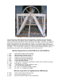
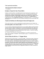
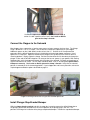
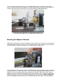
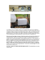
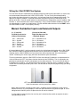
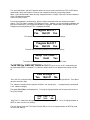
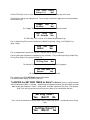
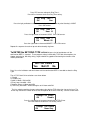
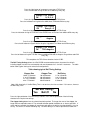
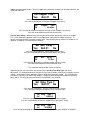
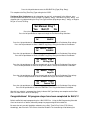
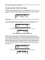
3 Bell
Programmable Church Bell Ringer
(3 Bell PCBR Plus and 3 Bell PCBR)
User’s Manual
Church Bell Ministry
Using Technology to Glorify GOD
General Description of the
3 Bell Programmable Church Bell Ringer
The 3 Bell PCBR system provides weekly scheduled control of bell ringing operations at your church.
The 3 Bell PCBR provides automated control for the 3 bells utilized in the Catholic three bell tower. The
large bell called the “DeProfundis” is usually used for the Funeral Toll ring when applicable. The middle
sized bell or “Angelus” bell used for the Call to Pray. It rings at 12 Noon and 6PM daily. The third and
small bell is used for announcement of a service or Time of Day Chime or just ringing! Actually, the 3 Bell
PCBR allows any of the bells to perform any of the described tasks. Each bell has six weekly
programmable Ring Times to ring your church’s bells for one minute with a selectable SINGLE
(Dong…Dong) or DOUBLE (Ding...Dong) ring pattern that will make your bells sound like the day they
were installed. An optional daily Time of Day Clock Chime can ring on the hour from 9AM to 6PM or at
9AM, 12PM, 3PM and 6PM or Noon only, or an Angelus Ring at Noon and 6PM. The 3 Bell PCBR’s
Sermon Saver software disables the TOD Clock Chime for two hours after any Ring Time has been
activated. There are no setting limitations for the six Ring Time Settings. They can activate the bell for
one minute ANY time of the week, EVERY week.
The 3 Bell PCBR Plus Box consists of a power supply, a Rabbit 2000 Embedded Computer, a 2 Line LCD
Display, an atomic clock radio receiver (WWVB) and peripheral circuits that operate the solenoids
mounted in the bell tower. These solenoids provide a mechanical impulse to move a bell clapper into the
side of the bell. Three manual remote doorbell pushbuttons activate the 3 Bell PCBR Plus for non
scheduled rings. The LCD Display provides complete softkey prompting using the two pushbuttons on
the front of the 3 Bell PCBR Plus Box. Accordingly, programming can be accomplished in minutes.
Programmed settings and the Quartz TOD Clock operation are maintained during power outages. The 3
Bell PCBR Box is identical to the 3 Bell PCBR Plus with the exception of the atomic clock radio receiver
functions including automatic Spring and Fall time changes and TOD accuracy updated to the second
daily.
3 Bell Programmable Church Bell Ringer Features
•
Six fully programmable weekly scheduled Ring Times ring each bell for one minute (18 total all
bells)
•
3 Bell PCBR Plus has an atomic clock radio receiver that automatically sets itself daily to the
exact time and provides set-forward and set-back daylight savings time adjustments
•
3 Bell PCBR utilizes a Quartz Time of Day Clock with accuracy within 1 minute per month
•
Single (Dong…Dong) or Twin (Ding…Dong) ring cycles for Ring Times that sounds like a
conventional rope bell
•
Daytime 9 to 6 o’clock Time of Day Clock Chime with five optional schedules and ring patterns
•
Sermon Saver disables TOD Chime for next 2 chimes after a Ring Time is activated
•
User settings are stored in Flash memory for memory retention and battery backup maintains
TOD Clock accuracy during power outage
•
Fuse (current and thermal) protected solid state solenoid driver output circuitry for maintenance
free, reliable, long life
•
Three Manual Pushbutton inputs for non scheduled bell ringing events. Each can be selected for
1) Single Ring 2) Double Ring 3) 25 ring Peal 4) Angelus Ring 5) Funeral Toll Ring
•
2 Line LCD display provides menu prompting for two button programming that can be completed
in minutes.
•
Completely self contained, 120vac - very low power – less than 2w (250w during bell strike)
•
Replaceable coin type battery
Installation of the 3 Bell Programmable Church Bell Ringer
The installation of the 3 Bell Programmable Church Bell Ringer is not difficult once the mechanical
concept is understood. Due to gravity, the bell’s clapper will hang straight up and down. A powerful
electric solenoid can be attached with linkage to the bottom of the clapper. Accordingly, the clapper can
be pulled with a good jolt for the stroke length of the solenoid. This maximum stroke is about 1 inch. If
the bell is rotated on its axis until the side of the bell is about one inch from the clapper, then fastened
down tightly, the powerful mechanical strike can be realized. In other words, the bell doesn’t move – just
the clapper! This is our bell tower installation task. Read through the following installation steps to
become familiar with how this can be accomplished for each of your three bells.
Materials Supplied with the 3 Bell PCBR Plus & 3 Bell PCBR Kits
1
4
3
3
3
6
3
40
16
4
1
3
3
each
each
each
each
each
each
each
each
each
each
each
each
each
3 Bell PCBR Plus Box or 3 Bell PCBR Box
Solenoids with 30 feet of wire for each bell
Solenoid Linkage (1 Double Linkage)
Pushbuttons and 30 feet of wire for each
Clapper Return Spring and bendable clip
12” Perforated Steel Strap with U-clamp
Plunger Stop Bracket/Bumpers
1“ Power Driver Screw (plunger stop brackets, tie down straps, solenoids and springs)
#8 Flat Washer (solenoids)
½” Black Wood Screw (mounts PCBR Box to wall)
1/16 “ shim (minimum solenoid gap)
3/8”-16 X1 3/4” Threaded Hex Standoff (Clapper)
3/8”-16 X 1 1/2” Threaded Stud (Clapper)
Materials required but not Supplied with the PCBR System
10 dabs
6 each
48 each
Loctite or Gorilla Glue for machine threads
2”x4”x8’ planks (probably cut in half)
Power Driver Screws or Nails for the 2x4 attachments
Tools required for Installation
Power Driver with Phillips Head Bit or Claw Hammer
Phillips Head Screw Driver (Power Driver Screws)
½ “ Hex Wrench
Introduce Yourself to Your Church Bells
Probably, every bell installation is a little different due to varying mounting frames, rope pulleys, swivel
mechanisms etc. However, the concept described is the same. The following installation sequence
should provide an acceptable solution regardless of minor variations encountered. It is advisable to
examine all three of your bell’s installation before attempting the actual 3 Bell PCBR installation. Things
to be looking for include the three bell’s frames for subframe attachment, the clapper bottoms for
linkage attachments and the rope/pulley mechanisms for fastening down the bells. This can allow for a
more exact material and installation assessment and prevent climbing up into the church bell tower more
than one time.
Create the Subframe for Mounting the Solenoid Components
The first task is to install a 2x4 that runs perpendicular to the bell’s rotation axis and is located 1 inch
below the bell’s clapper. In other words, the clapper will swing directly in line with our 2x4. This will serve
as the mounting platform for the solenoid assembly.
This can usually be accomplished by positioning two 2x4 cross members opposite each other mounted
to the bell’s frame ends. With the tall dimension or 4” mounted vertical to the frame ends, a pair of very
rigid and strong cross members is accomplished. These 2x4s are mounted parallel to the bell rotation
axis, at the appropriate height so that a 2x4 positioned on top of them will be 1 inch below the clapper.
The lengths of these boards are determined by your particular bell installation. Fasteners for mounting
these boards could be power driver screws or nails.
Let’s summarize. We should have a rigid mounting board that is in line with the swing of the bell’s
clapper and located about 1 inch below it. Refer to the photo on page 4. Our subframe 2x4s are those
that are unpainted.
Anchor Down the Bell for a 1” Clapper Stroke
Rotate the bell until the inside surface is 1 inch from the clapper. The direction of rotation will determine
which side of the clapper that the solenoid will be mounted. If access is easier on one side, take the
better choice. Once this is determined, fasten down the bell position with the 1 inch distance as above.
This can probably be best accommodated using the rope pulley or linkage that was used for ringing the
bell manually. The rope or chain should be completely disabled. The rotation mechanism can usually be
employed to hard mount the bell position using the supplied U-clamp and perforated steel straps. As
necessary, power driver screws or nails can be used to anchor the straps to the bell frame. Dab Loctite
or Gorilla Glue on the U-clamp threads to maintain a tight mechanical connection. It is important
that the bell position be held solid to maintain the appropriate solenoid travel or stroke to maximize the
clapper ring force!
Connect the rope wheel clamp to the perforated steel straps to
anchor the bell in position to the frame. Use Loctite or Gorilla
glue on the clamp’s threads.
Connect the Clapper to the Solenoid
Most clappers have a protrusion, a hook or some means to fasten a rope or chain to them. The linkage
hinge is drilled for 1¼” or 2” U Clamps. Use the one best suited for the protrusion on your clapper.
Additional spacers on the U bolt allow it to close to less than ¼”. Position the U Clamp around the
protrusion with the drilled linkage bar facing in the direction of the desired clapper movement. Hand
tighten the U Clamp nuts. Adjust the rotation of the linkage to line up directly in the center of the 2x4
mounting platform. Slightly tighten the clamp. Position the solenoid and insert the cotter pin through the
plunger’s holes and the drilled linkage bar. For now, put the hex nut spacers in your pocket. With nothing
tied down tight, verify the clapper movement with the stroke of the solenoid. Pull back on the plunger to
ring the bell and then let it relax. The full stroke should be about 1 inch. If all looks good, tighten both U
Clamp nuts securely. Use Loctite or Gorilla glue on the clamp’s threads. Verify that the solenoid
position is centered on the 2x4 mounting platform. If your clapper does not have a protrusion, refer to the
simple clapper modification options described on page 11.
Clapper and linkage connection using the Hex Standoff protrusion.
Install Plunger Stop Bracket/Bumper
With the clapper hanging vertical and with the cotter pin inserted to connect the drilled linkage bar to
the plunger, position the solenoid frame on the 2x4 platform so the plunger gap is one inch. This
positions the linkage for installation of the plunger stop bracket/bumper. Position the stop bracket/bumper
on the 2x4 directly in front of the plunger. This bracket/bumper cushions the rebound of the clapper
strike. Mark the bracket holes on the platform. Remove the cotter pin and slide the solenoid frame and
linkage out of the way to gain vertical access for screw mounting the stop bracket/bumper.
Install the plunger stop bracket to capture the plunger at 1 inch.
Flat washers are used on the screws mounting the solenoid base.
Mounting the Magnetic Solenoid
Reposition the solenoid and reinstall the cotter pin this time inserting a hex nut spacer on each side of the
drilled linkage bar to center it on the pin. Pull the solenoid plunger in until the clapper is pressed against
the side of the bell. Position the solenoid for a 1/16” gap using the supplied shim.
1/16 “ shim must fit loosely for proper solenoid gap adjustment.
Install a flat washer and screw in the center of each oblong slot on rear of the solenoid’s frame. Tighten
them down where it is still possible to slide it. Verify the minimum gap by placing the supplied 1/16” shim
between the rear of the plunger and the laminated face of the solenoid. Adjust if necessary. Slightly
tighten the rear screws to secure the position. Install a flat washer and screw in the front mounting holes
of the solenoid frame. Verify the 1/16” gap and tighten all four screws securely. When the clapper hits
the bell, the plunger must be at least 1/16” from bottoming out to the frame. This will maximize
the strike force of the clapper to the bell and the life of the solenoid. If the solenoid bottoms out, a
secondary impact sound can be heard detracting from the natural sound of the bell. Verify that all four
solenoid mounting screws are secure.
Install the clapper return spring on the opposite side from the solenoid. Since the U Clamp is probably
wider than the clapper protrusion, the return spring clip can be usually connected down through the U
bolt. Stretch the spring about 1 inch and terminate it with a screw mounted on the 2x4 platform.
Using your fingers, squeeze the solenoid to ring the bell, verify that the movement to the bell and its
return are smooth and the clapper return is cushioned by the rubber bumper. If the movement looks
good, bend the long end of the cotter pin to secure a long maintenance free life! Connect the solenoid to
the PCBR Box using the supplied wire with quick connect terminals for the solenoid coil.
Verify the Installation of the Moving Parts
You should be able to simulate the solenoid action. Push the plunger in as though the magnetic coil was
energized. The bell should sound as the plunger approaches the bottom of its stroke. A minimum 1/16”
gap should be realized. Release the plunger and allow the clapper to return on its own. The clapper
movement should be smooth and non binding in any way. It should stop right at vertical from the plunger
stop bracket/bumper. If the movement and travel look good, this completes the Bell #1 portion of the 3
Bell PCBR Plus installation.
Large bells often have a spring damper that interferes with the clapper travel. See the webpage
application note on this item.
If the fuse is replaced, it must be replaced with a 4 Amp Slo Blo only! The Slo Blo feature allows the
solenoid pulses to exceed the 4 amp rating, but prevents overload if a fault occurs.
Repeat the preceding installation steps for Bells #2 and #3.
The BIG bell’s clapper linkage attaches to two solenoids using a steel connecting strap. One solenoid
box is marked as FRONT. The plunger receiver on this one has been spread minutely to accommodate
the forked end of the steel connecting strap.
Insert the cotter pin into the plunger hole and through the drilled linkage bar as on the bell before. Position
the solenoid frame on the 2x4 platform so the plunger gap is one inch. This positions the linkage for
installation of the plunger stop bracket/bumper. Position the stop bracket/bumper on the 2x4 directly in
front of the plunger. Mark the bracket holes on the platform. Remove the cotter pin and slide the solenoid
frame and linkage out of the way to gain vertical access for screw mounting the stop bracket/bumper.
Now reinsert the cotter pin, but, this time include the fork of the steel connecting strap along with the
drilled linkage bar. Push the pin through as far a possible. Adjust the front solenoid plunger gap using the
1/16” shim as before. After verifying the one inch stroke and the 1/16” gap, tighten down the front
solenoid using flat washers with each screw. Position the rear solenoid and insert the cotter pin through
the plunger hole, then through a hex nut spacer, then through the steel connecting strap, then through
another hex nut spacer and finally through the other hole. Adjust the rear solenoid gap using the shim as
before. After verifying the one inch stroke and the 1/16” gap on the rear solenoid, tighten it down using
flat washers with each screw.
A template is supplied to assist in positioning the solenoid pair but use it as a guide only.
Use your fingers as before, squeeze the rear solenoid to ring the bell. Verify the movement of both
solenoids and the bell clapper. The motion should be smooth and the clapper return is cushioned by the
rubber bumper. If the movement looks good, bend the long end of both cotter pins. Push in the quick
connect terminals to both solenoids to connect them to the PCBR Box.
Double Solenoid shown with Steel Connecting Strap.
A PVC Solenoid Cover is used for outdoor installations.
The PCBR Box controls the clapper movement by user programmable settings for the appropriate
solenoid activation time to accelerate the clapper into the bell but not hold the clapper against the bell.
The bigger the clapper, the longer the time required to get it going. Ideally, this activation time would
terminate at the instant the clapper strikes the bell. Realistically, four selections are available in the
programming menu. Pick the one for your clapper size that does not hold the clapper against the bell.
This can be identified by a muffled sounding ring. Set too short yields an intermittent ring.
While on the subject of clappers, what if my clapper does not have a protrusion which connects to the
solenoid linkage? Many do not! No problem. If your installation team can drill and tap a 5/16”–18
threaded hole about 1” deep at the very bottom of the clapper, the supplied threaded stud and hex
standoff can be installed to accommodate a strong linkage connection. If this is not an alternative, no
problem. An inexpensive alternative that can be applied in all cases requires only a hand drill and a
drill bit. This approach uses a hickory handle sledge hammer whose mass is selected to be similar to
the original clapper. The handle length can be cut to fit the radius required for your bell size and a
wood screw hook-eye can connect through the pin or bolt used to hang it in the bell. A ¼” pilot hole
drilled 1 ½” deep into the soft spot on the hammer end can fasten the with a lag bolt the supplied hex
standoff to the new clapper for the linkage attachment. The cost for this alternate clapper is less than
$10 and the bell sounds just fine!
CAUTION – DO NOT GET FINGERS BETWEEN MOVING PARTS. The solenoid force can cause
serious injury !
Wiring the 3 Bell PCBR Plus System
Pass the three wire pairs attached to the solenoids through the flooring of the bell tower in a manner that
can accommodate connection to the 3 Bell PCBR Plus Box. This can usually be accomplished by
passing the wires down through the same hole in the bell tower floor that the rope passed through. The
rope will no longer be needed. It should be removed or someone may pull on it and change the tilt
position of the bell. Since this would reduce the solenoid efficiency, the possibility must be avoided. Strip
the wires ¼” and insert them one at a time into the plug. Using a small flat blade screwdriver, terminate
the solenoid pairs as shown in the table below. Plug the solenoid cable connector into the RIGHT side of
the 3 Bell PCBR Plus Box. It lines up only one way.
Manual Pushbutton Inputs and Solenoid Outputs
(0 – 5 Volts DC)
Left Side Connector for
3 Manual Pushbuttons
pin 1 – PB Input #1
pin 2 – Ground
pin 3 – PB Input #2
pin 4 – Ground
pin 5 – PB Input #3
pin 6 – Ground
(Pulsed 120 Volts AC)
Right Side Connector for
3 Solenoid Outputs
pin 1 – Solenoid #1 Out
pin 2 – AC Neutral
pin 3 – Solenoid #2 Out
pin 4 – AC Neutral
pin 5 – Solenoid #3 Out
pin 6 – AC Neutral
If the provided wire (30 ft) is not long enough to reach the desired mounting location of the 3 Bell PCBR
Box, standard 18 AWG 2 conductor lamp cord wire can be spliced with that supplied. The connectors
that plug into the 3 Bell PCBR Box have screw terminals and can be loosened, wires removed and
reused. Performing this minor surgery eliminates two electrical splice connections.
The wiring connections from the 3 Bell PCBR Plus Box to the Manual Pushbuttons are implemented in a
similar fashion on the LEFT side (when view from the front) of the PCBR Box. The six connections are
paired up to coincide with the three solenoid pairs on the other connector. This assures Bell #1 Manual
Pushbutton will ring Bell #1. As indicated earlier when wiring the solenoids, there is no polarity to keep
track of with the manual pushbuttons pairs either. See the table on the previous page to verify your wiring
assignments.
LEFT side connector shown for the 3 Manual Pushbuttons.
Insert the connectors until they lock (click) in place.
When splicing the wires to lengthen them, there is no polarity of the 2 conductors so they cannot
become reversed. Be sure to properly insulate the splice connection using electrical tape or shrink
tubing because 120 VAC pulses are present on the wire to the solenoid.
If using staples to route the wires, be sure they are insulated and be careful not to pinch the wires
from pounding in too far.
The Manual Ring Pushbutton Input cable connector plugs into the LEFT side of the PCBR Box. It
only goes in one way.
Do not connect this cable to the Solenoid output connector that is located on the
RIGHT side of the 3 Bell PCBR Plus Box !
Plug the 3 Bell PCBR Plus Box into a standard 120vac outlet. The display will show the Software
Release Revision, Rx.x and Initialize the atomic clock radio receiver. The Date and Time will
appear in the LCD Display. Press the Manual Ring Pushbutton. Wow! Did you hear it?
Try it again. I’ll bet it sounds great.
Considerations locating and mounting the 3 Bell PCBR Box.
•
Installation could be the most straight forward in the same location where the rope was located.
The mounting flange provides easy installation on a beam or wall below or near the bell tower. It
should be mounted high enough to be out of reach of children.
•
Mount the 3 Bell PCBR Box out of any heavy traffic areas.
•
The 3 Bell PCBR Box should be positioned to allow easy viewing of the 2 line LCD display. The
replaceable coin battery will need occasional access too.
•
Installation location could include the PA/Audio Booth if the location is suitable. Many PA Booths
have ports to the attic to run microphone and speaker cables – maybe a solenoid.
•
The 3 Bell PCBR Plus should not be mounted in the basement due to radio wave attenuation.
Installation Notes
______________________________________________________________________
______________________________________________________________________
______________________________________________________________________
______________________________________________________________________
______________________________________________________________________
______________________________________________________________________
______________________________________________________________________
______________________________________________________________________
______________________________________________________________________
______________________________________________________________________
______________________________________________________________________
______________________________________________________________________
______________________________________________________________________
______________________________________________________________________
______________________________________________________________________
______________________________________________________________________
______________________________________________________________________
______________________________________________________________________
______________________________________________________________________
______________________________________________________________________
______________________________________________________________________
______________________________________________________________________
Programming the 3 Bell PCBR and the 3 Bell PCBR Plus
Programming the 3 Bell PCBR is fast and easy using the two pushbuttons on the front panel. When the
menu is selected, the function of each Pushbutton is shown in the display. The following items can be
programmed into the PCBR.
•
•
•
•
•
•
Setting of up to Six Ring Times for each bell that activate each bell for one minute on a weekly
schedule
For the 3 Bell PCBR Plus, Time Zone selection, Radio Receiver Setup (pointing antenna)
For the 3 Bell PCBR, Setting of Time of Day Clock and Calendar Date
Select Time of Day Clock Daytime Chime
Setting of Timing Characteristics for each of the three bell sizes
Select the ring functions of the three Manual Pushbuttons
The TOD Clock is set at the factory and the default settings of the PCBR do not activate the bell solenoid
until the user programming has been accomplished.
The normal display of the PCBR shows the date and time.
There is a 3 Bell Programming Reference Sheet printed on the back page of this manual. Make a copy
for a worksheet to write down expected programming settings for your bells.
The three circuits and software functions of the 3 Bell PCBR are fully replicated and do not require
specific wiring to a specific bell.
For example, the Funeral Toll ring can operate on all three bells even though the Big Bell usually carries
that function. According, it is necessary for the user to define the bell assignments and select and/or
disable the programmed functions of each. As a caution when given this flexibility – only enable ONE bell
for the TOD Chime. The other two bell’s TOD Chime must be disabled!
To ENTER the PROGRAMMING MENU, push both buttons simultaneously. To enter each submenu,
hold the two pushbuttons down until the LCD display changes to the Name of menu item and the
confirmation BEEP is sounded. The LCD display will show the first of four categories of the programming
menu. To skip entering this or the other submenu levels, press both pushbuttons but do not hold them
down. Each time both pushbuttons are pressed, the submenu is indexed to the next programming
category.
The Top Level Programming Menu categories are:
•
Program Bell #1 ? Provides entry into the programming steps for Bell #1
•
Program Bell #2 ? Provides entry into the programming steps for Bell #2
•
Program Bell #3 ? Provides entry into the programming steps for Bell #3
•
Setup the TOD Clock – Sets the time and date (Setup the Clock – PCBR Plus) Sets Time Zone
Program Bell #1 ?
Yes
Bell #1 Yes
Push both buttons simultaneously. To enter each submenu, hold the two pushbuttons down until the LCD
display changes to the next menu item and the confirmation BEEP is sounded.
This “push two buttons and hold” sequence allows the user to enter each of the four TOP LEVEL Menus
and provides some small amount of security from someone entering by just pushing a button.
Note: If you hold the buttons down too long, unexpected entries or jumps in the menu will occur because
of the slew data entry method
used in the 3 Bell PCBRs.
Press both pushbuttons simultaneously, but then release them before the two second time window
expires. The TOD Clock/ Calendar LCD Display will return. However, the next time both pushbuttons are
pressed simultaneously, the Program Bell #2 Menu is displayed. If both buttons are held down, Bell #2
Programming can be performed. This is repeated for Bell #3.
Program Bell #2 ?
Yes
Bell #2 Yes
The second Top Level Menu provides entry for Bell #2 settings.
Program Bell #3 ?
Yes
Bell #3 Yes
The third Top Level Menu provides entry for Bell #3 settings.
Setup TOD Clock ?
Yes
Hold
Yes
The fourth and last Top Level Menu provides entry for TOD Clock.
To ENTER the VIEW SETTINGS for Bell #1, press the Yes or left button down until
the confirmation BEEP is sounded. This submenu section shows all user programmed settings for Bell
#1.
View Settings ??
Yes
Bell #1 No
Press the Yes or left pushbutton to sequence through each current User Setting for Bell #1. Press No to
go to the next menu step.
This submenu selection allows inspection of Bell #1 user settings only! – no programming is performed
in this submenu category.
The weekly Ring Times are displayed first. Pressing the right pushbutton will increment each of the six
Ring Time settings.
Ring
Sun
Time
9:50
1 is
Nxt
Ring Time 1 is shown with setting to ring Bell #1 Sunday morning at 9:50. Press the right pushbutton or
NEXT to show the next User Settings.
The next display shows the TOD Clock Chime for Bell #1. Press the right pushbutton or NEXT to show
the next User Settings.
TOD Clock
Every 9 – 6
Chime
Nxt
The bell TOD Daily Chime is set to ring every hour from 9 AM to 6PM every day of the week.
The bell timing settings are displayed next. These settings include the clapper pulse time and the delay
time between rings.
Clapper Time
60 mSec
is
Nxt
This Clapper Time is set to activate the solenoid for 60 milliseconds
Bell Delay Time
2.5 Seconds Nxt
This Bell Delay Time is set for a 2.5 second delay between rings.
The six weekly Ring Times can be selected for a SINGLE ring (Dong…Dong) or a DOUBLE ring
(Ding…Dong).
Ring Time
SINGLE
Type
Nxt
The six programmed ring times will ring with a SINGLE (Dong…Dong) ring pattern.
The Ring setting for the Manual Pushbutton has five selections. They include Single Ring, Double Ring,
25 Ring Peal, Angelus Ring and the Funeral Toll.
Manual Pushbutton
25 Ring Peal
Nxt
This Manual Pushbutton is selected for a 25 Ring Peal ring pattern.
The Time Zone is
Eastern
Nxt
For the PCBR Plus, the Time Zone is identified.
This completes the VIEW SETTINGS category of the Menu.
The clock /calendar display will return to the LCD.
To ENTER the SET RING TIMES for Bell #1 submenu, press the left pushbutton
until the confirmation BEEP is sounded. Step through each prompt and enter your desired day and time.
Note the day after Saturday is “None”. Select “None” to disable a particular Ring Time. The selected
Ring Times will ring your bell for one minute every week at the selected day and time.
Set Ring Times ?
Yes
Bell #1 No
Press Yes or the left button and hold it down until the confirmation BEEP is sounded to Set the 6 Ring
Times.
Set Ring Time #1 ?
Yes
Bell #1
No
Press YES to enter settings for Ring Time 1.
Press NO to increment to the next Ring Time setting.
Set Ring Time 1
OK
Sun
Press the right pushbutton to increment each day of the week. The day after Saturday is NONE.
Press OK to enter.
Set Ring Time 1
OK
Hour 10
Press the right button to increment HOUR. Press OK to enter.
Set Ring Time 1
OK
Minute 50
Press the right button to increment MINUTE. Press OK to enter.
Repeat this sequence for each of up to 6 desired weekly ring times.
To ENTER the SET RING TYPE submenu, press the left pushbutton until the
confirmation BEEP is sounded. These program settings include daily TOD Clock chime options, the
clapper stroke timing, bell delay timing, single or double ring option and selecting the function of the
manual pushbutton.
Set TOD Chime ?
Yes
Bell #1 No
Press Yes or the left button and hold it down until the confirmation BEEP is sounded to select the Ring
Type.
The six TOD Clock Chime selections are shown below.
1) Disable
2) 12 Noon Only
3) 9AM, 12 Noon, 3PM & 6PM
4) Every hour from 9AM – 6PM
5) Angelus Ring at 12 Noon and 6PM
6) TOD Every hour 9AM – 5PM and Angelus at 12 Noon and 6PM
The first selection provides changes to be made to the daytime TOD chime that rings on the hour. The
chime rings the bell the number of times that corresponds to the hour of the day. Just like a clock chime.
Change TOD Chime
OK
Disable
Press the right button to increment to each type of TOD Chime.
Press left button to disable the Time Of Day Chime.
Change TOD Chime
OK
Noon Only
Press the right button to increment to next type of TOD Chime.
Press the left button to ring the bell at 12 Noon only every day.
Change TOD Chime
OK
9, 12, 3, 6
Press the right button to increment to next type of TOD Chime.
Press the left button to ring the bell at 9AM, Noon, 3PM and 6PM every day.
Change TOD Chime
OK
Every 9 - 6
Press the right button to increment to the next type of TOD Chime.
Press the left button to ring the TOD Bell Chime EVERY hour on the hour from 9AM to 6PM every day.
Change TOD Chime
OK
Angelus
Press the right button to increment to the next type of TOD Chime.
Press the left button to ring bell with the Angelus ring pattern at 12 Noon and 6PM every day.
Change TOD Chime
OK
TOD+Angelus
Press the right button to increment to the next type of TOD Chime.
Press the left button to ring the TOD Bell Chime at 9AM to 5PM and the Angelus Ring at Noon and 6PM
every day.
This completes the TOD Chime selections for the PCBR.
The Bell Timing Settings allows the 3 Bell PCBR to accommodate various characteristics of bells
including clapper size, bell size and material and most important of all – the bell’s resonance. The table
below shows typical settings for various bell configurations.
Table showing typical Bell Timing Settings
Clapper Size
Under 2” Diameter
2” to 3.5” Diameter
3.5” to 5” Diameter
over 5” Diameter
Clapper Time
30 milliSeconds
60 milliseconds
60 milliseconds
90 milliseconds
Bell Delay
1.5 or 2 Seconds
2 or 2.5 Seconds
2.5 or 3 Seconds
3 Seconds
Note: With large bells, if the Bell Delay Time is set too short, the fuse can blow. If this occurs, increase
the Bell Delay Time.
Set Bell Timing ?
Yes
Bell #1
No
Press the right pushbutton if the bell timing is correct. Press the left pushbutton if the bell timing
characteristics require new settings.
The clapper timing determines the solenoid activation period. The larger the mass of the clapper, the
longer the time required to move it. The solenoid activation period should be set as short as possible. If
set for too long a period, the clapper will remain pressed against the bell by the solenoid while it is trying
to ring. The result is a muffled sounding ring. The best setting is as short as possible that allows the
clapper to make reliable contact. The four clapper timing selections available are 30 mSec, 60 mSec, 90
mSec and 150 mSec.
Set Clapper Time ?
Yes
Bell #1
No
Press the right pushbutton if the clapper time is correct.
Press the left pushbutton to change the Clapper Time setting.
Set
OK
Clapper
Time
60 mSec
Press the right pushbutton to sequence through the four Clapper Time settings.
Press the left pushbutton to enter the desired value.
The bell delay timing is determined by how long the bell resonates after being struck by the clapper.
This is more a personal judgment rather than an operational setting like the clapper timing was. In
general, the bigger the bell, the longer the delay time. Four bell delay timing selections available are 1.5
Seconds, 2 Seconds, 2.5 Seconds and 3 Seconds.
Set Bell Delay ?
Yes Bell #1
No
Press the right pushbutton if the bell delay time is correct.
Press the left pushbutton to change the Bell Delay Time setting.
Set
OK
Bell
Delay ?
2.5 Sec
Press the right pushbutton to sequence through the four settings.
Pess the left pushbutton to enter the desired value.
This completes setting the Bell Timing for Bell #1.
Depending on the size of the bell or just personal taste, the Ring Time Ring Type may desire
adjustment. This selection determines the type of ring (single or double) used for the six weekly ring time
settings. Smaller bells have a “ding-dong” type of sound when pulled with a rope. The PCBR Box can
simulate this ring using a DOUBLE ring selection. Large bells when pulled with the rope just go “dong,
dong…dong”. This ring type can be selected using the SINGLE ring selection.
Set Ring Type ?
Yes
Bell #1
No
Press the right pushbutton if the Ring Time Ring Type is correct.
Press the left pushbutton to change the Ring Time Ring Type.
Set Ring Type ?
OK
SINGLE
Press the right pushbutton to sequence through the two ring types.
Press the left pushbutton to enter the SINGLE Ring Type (Dong…Dong).
Set Ring Type ?
OK
DOUBLE
Press the right pushbutton to continue to sequence through the two types (SINGLE or DOUBLE).
Press the left pushbutton to enter the DOUBLE Ring Type (Ding..Dong).
This completes the Ring Time Ring Type setting for the PCBR.
The Manual Ring Pushbutton can be selected to ring your bell “on demand” in five different ways.
Each pushbutton activation can initiate a SINGLE ring (dong…dong), a DOUBLE ring (ding…dong), a 25
ring peal with a ring determined by the Ring Time Type selection (ding-dong or dong… dong), an Angelus
Ring or a Funeral Toll Ring.
Set Manual Ring ?
Yes
Bell #1
No
Press the right pushbutton if the Manual Ring selection is correct.
Press the left pushbutton to sequence through the five Manual Ring Selections.
Set Manual Ring ?
OK
SINGLE
Press the right pushbutton to sequence through each of the five Manual Pushbutton Ring settings
Press the left pushbutton to select a SINGLE ring (Dong…Dong) for the Manual Pushbutton.
Set Manual Ring ?
OK
DOUBLE
Press the right pushbutton to sequence through each of the five Manual Pushbutton Ring settings.
Press the left pushbutton to select a DOUBLE ring (Ding...Dong) for the Manual Pushbutton.
Set Manual Ring ?
OK
25 Ring Peal
Press the right pushbutton to sequence through each of the five Manual Pushbutton Ring settings.
Press the left pushbutton to select 25 Ring PEAL (about 1 minute) for the Manual Pushbutton.
Set Manual Ring ?
OK
Angelus
Press the right pushbutton to sequence through each of the five Manual Pushbutton Ring settings.
Press the left pushbutton to select an ANGELUS Ring for the Manual Pushbutton.
Set Manual Ring ?
OK
Funeral Toll
Press the right pushbutton to sequence through each of the five Manual Pushbutton Ring settings.
Press the left pushbutton to select the FUNERAL TOLL Ring for the Manual Pushbutton.
After this last selection is prompted, the display indicates Bell Type Settings are complete and the Date
and TOD Clock returns to the LCD display.
Congratulations! All program steps have been completed for Bell #1 !
Bell #2 and Bell #3 require programming the 3 Bell PCBR Plus. Using the Bell Programming Schedule
Chart for these bells as before, follow the prompts for programming bell #2 and bell #3.
Be aware that only one bell should be selected to ring a Daily Time Of Day Chime (TOD Chime).
Accordingly, two of the bells TOD Chimes should be disabled. The shortcoming of not following this
advisement is a TOD Chime conflict. If all three bells were enabled, they would ALL announce the hourly
chime in order from Bell #1 to Bell #3. Not good!
Calendar and Time Of Day Clock Setup
To ENTER the SETUP TOD CLOCK submenu for the 3 Bell PCBR Plus, push both buttons to get the
TOD prompt, then hold the two pushbuttons down until the confirmation BEEP is sounded. This submenu
entry sets the Time Zone, Radio Setup and Manual Setting of the Calendar Date and the Time Of Day
Clock.
Setup The Clock ?
Yes ---- Hold ---- Yes
As before, the RIGHT Pushbutton selects the value and the LEFT Pushbutton enters the desired data into
the computer.
The first menu prompt provides entry for Changing the Time Zones. The 3 Bell PCBR Plus supports the
time zones for continental US and Canada, namely Eastern, Central, Mountain and Pacific.
Change Time Zone
Yes
No
Press the left pushbutton to set or change the Time Zone.
Press the right pushbutton to increment to the next TOD Clock menu selection.
Change Time Zone
OK
Eastern
Press the right pushbutton to increment to the next time zone.
Press the left pushbutton to set or change the Time Zone.
The next menu prompt provides an Atomic Clock Radio Receiver Broadcast Signal Indicator. The
WWVB transmitter is centrally located in Fort Collins, Colorado to allow radio reception from coast to
coast. The signal frequency of 60KHz is at the very bottom of the radio frequency spectrum to allow long
distance reception, but is corrupted by the sun and other radio interference during the day. Accordingly,
the most available signal occurs after midnight. The 3 Bell PCBR Plus has an external antenna that can
be pointed to optimize signal reception. The best way to aim the antenna is with a compass and a map of
the US to best recognized where you are with respect to Colorado. The antenna should be rotated so
that the flat of the antenna (not the end) is positioned toward Colorado. Note that there is no antenna
front or back. The antenna is designed to rotate to the left or to the right just under 90 degrees to allow
optimized positioning.
Setup
Yes
Receiver ?
No
Press the Left Pushbutton to Setup the Receiver.
Press the Right Pushbutton to move on to the next TOD Clock menu selection.
Signal Strength
BSI = >>>>>> Quit
Press and hold the Right Pushbutton until the confirming beep is heard to exit the Signal Strength
Indicator.
Unfortunately, the Broadcast Signal Indicator (BSI) will probably not show any bars during the daytime
hours. Even during the evening, results will vary depending on weather disturbances between you and
Fort Collins, Colorado. In some cases metal structural building materials that can cause shielding of the
signal can adversely affect reception. Do not mount the 3 Bell PCBR Plus Box in the basement.
The next menu prompt provides for manually setting the Time Of Day Clock on the 3 Bell PCBR Plus.
Press Yes to adjust. This operation is the same as for the 3 Bell PCBR clock setting sequence as shown
below
Manual Clock Set
Yes
No
To ENTER the SET TOD CLOCK submenu for the PCBR, push both buttons to get the TOD prompt,
then hold the two pushbuttons down until the confirmation BEEP is sounded. This entry sets the
Calendar Date and the Time Of Day Clock. The RIGHT Pushbutton selects the value and the LEFT
Pushbutton enters the data into the computer.
Set Clock Time ?
Yes ---- Hold ---- Yes
For the PCBR, press both buttons and hold them down to Set the Date and Time.
Set Year 09 – 47
OK
Year 2011
The first prompt sets the YEAR. Press the right pushbutton to
increment the year to the desired value. Press OK to enter.
Set
OK
Month
Aug
The next prompt sets the MONTH. Press the right pushbutton to
increment the month to the desired value. Press OK to enter.
Set Day of Month
OK
Day 17
The next prompt sets the DAY. Press the right pushbutton to
increment the day to the desired value. Press OK to enter.
Set
OK
Hour
0 - 23
Hour 21
The next prompt sets the HOUR. Press the right pushbutton to
increment the hour to the desired value. Press OK to enter.
Set Minutes 0 – 59
OK
Minute 39
The next prompt sets the Minutes. Press the right pushbutton to
increment the minutes to the desired value. Press OK to enter.
As a reminder, to avoid entering a submenu, allow the Date and TOD Clock to return the LCD display
after the submenu item is displayed.
The 3 Bell PCBR Plus synchronizes with the Atomic Clock every day at 5AM if a valid data packet is
received. This is indicated in the upper left corner of the LCD with an asterisk ( * ).
The normal display on the 3 Bell PCBR Plus is the Date and the Time Of Day. If the TOD Clock is not
displayed as above, the PCBR is in one of the Programming Modes and the bell will not ring as expected.
When programming is complete, the values selected are stored in nonvolatile FLASH memory and will be
maintained during a power outage. In addition, the replaceable coin type battery maintains accurate
Time OF Day Clock operation.
Routine Maintenance consist of Battery Replacement
The Time of Day Clock circuitry has continued operation when the power cord is disconnected or a power
outage occurs. Even though the bell will not ring under these conditions, to eliminate any maintenance to
the 3 Bell PCBR Plus, the clock hardware continues to tick away with the same accuracy as with the 120
VAC power applied. The 3 Bell PCBR Plus is equipped with a 3 volt, 20mm, 165 mAHr coin battery
(Panasonic CR2025). It is located under the front cover of the PCBR and can be accessed by removing
the four screws holding it in place. Be sure to remove the power cord prior to any internal replacement
service.
Church Bell Ministry
http://churchbellministry.com
Dave Smith
email: [email protected]
1900 Glen Echo Road
Jonesborough, Tn. 37659
ph 423 926 3685
cell 423 747 0585
Write down your Settings for Data Entry and for future reference.
BELL # 1
Bell Function _____________
Ring Time 1: ___________ Ring Time 2: ___________
Ring Time 3: ___________ Ring Time 4: ___________
Ring Time 5: ___________ Ring Time 6: ___________
TOD Chime:
___Disable ___Noon
___9,12,3,6 ___Every 9-6
(Disable two)
___Angelus ___TOD+Angelus
Clapper Time:
Bell Delay:
___30mSec ___60mSec ___90mSec ___120mSec
___1.5Sec ___2.0Sec
___2.5Sec ___3.0Sec
Ring Type:
___ SINGLE ___DOUBLE
Manual PB:
___SINGLE ___DOUBLE ___25 Peal ___ Angelus
___Funeral Toll
BELL # 2
Bell Function _____________
Ring Time 1: ___________ Ring Time 2: ___________
Ring Time 3: ___________ Ring Time 4: ___________
Ring Time 5: ___________ Ring Time 6: ___________
TOD Chime:
___Disable ___Noon
___9,12,3,6 ___Every 9-6
(Disable two)
___Angelus
___TOD+Angelus
Clapper Time:
Bell Delay:
___30mSec
___1.5Sec
___60mSec ___90mSec ___120mSec
___2.0Sec ___2.5Sec ___3.0Sec
Ring Type:
___ SINGLE ___DOUBLE
Manual PB:
___SINGLE ___DOUBLE ___25 Peal ___ Angelus
___Funeral Toll
BELL # 3
Bell Function ______________
Ring Time 1: ___________ Ring Time 2: ___________
Ring Time 3: ___________ Ring Time 4: ___________
Ring Time 5: ___________ Ring Time 6: ___________
TOD Chime:
___Disable ___Noon
___9,12,3,6 ___Every 9-6
(Disable two)
___Angelus ___TOD+Angelus
Clapper Time:
___30mSec
___60mSec ___90mSec ___120mSec
Bell Delay:
___1.5Sec
___2.0Sec
Ring Type:
___ SINGLE ___DOUBLE
Manual PB:
___SINGLE ___DOUBLE ___25 Peal ___ Angelus
___Funeral Toll
___2.5Sec
___3.0Sec


![[PF03] User manual for RED DOT CLUSTERS(EN) - Auto](http://vs1.manualzilla.com/store/data/005713867_1-90b7ac4617a5dc924635c3e0ee039806-150x150.png)