1
DelfiScan C80
Programming Manual
Delfi Technologies A/S
Galoche Alle 1
DK-4600 Køge
Denmark
Telephone: + 45 70 222 555
Fax: + 45 70 222 666
An Unpublished Work - All rights reserved. No part of the contents of this
documentation or the procedures described therein may be reproduced or
transmitted in any form or by any means without prior written per-mission of
Delfi Technologies A/S. Owners of Delfi products are hereby granted a nonexclusive, revocable license to reproduce and transmit this documentation for the
purchaser's own internal business purposes. Purchaser shall not remove or alter
any proprietary notices, including copyright notices, contained in this
documentation and shall ensure that all notices appear on any reproductions of
the documentation.
Electronic versions may either be downloadable from the Delfi website
(www.delfi.com) or provided on appropriate media.
Disclaimer
Delfi has taken reasonable measures to provide information in this manual that is
complete and accurate, however, Delfi reserves the right to change any
specification at any time without prior notice.
CONTENTS
1
INTRODUCTION ........................................................................................ 1
2
INITIAL SETUP ........................................................................................... 3
3
CONFIGURATION....................................................................................11
USB PARAMETERS ..................................................................................12
Handshaking................................................................................................................. 13
Ack/Nack Protocol ...................................................................................................... 13
Fifo ................................................................................................................................... 13
Inter-character Delay ................................................................................................. 14
Rx Timeout .................................................................................................................... 15
Serial Trigger Lock ...................................................................................................... 15
Keyboard Nationality ................................................................................................. 16
Fifo ................................................................................................................................... 16
Inter-character Delay ................................................................................................. 17
Inter-code Delay .......................................................................................................... 17
Control Character Emulation .................................................................................. 18
RS232 PARAMETERS ..............................................................................19
Baud Rate ....................................................................................................................... 20
Parity................................................................................................................................ 21
Data Bits ......................................................................................................................... 21
Stop Bits ......................................................................................................................... 21
Handshaking................................................................................................................. 22
Ack/Nack Protocol ...................................................................................................... 22
Fifo ................................................................................................................................... 23
Inter-character Delay ................................................................................................. 24
Rx Timeout .................................................................................................................... 24
Serial Trigger Lock ...................................................................................................... 25
WEDGE PARAMETERS ............................................................................26
Keyboard Nationality ................................................................................................. 27
Caps Lock ....................................................................................................................... 28
Caps Lock Auto-Recognition (IBM AT compatible only) ................................. 28
Num Lock ....................................................................................................................... 29
Inter-character Delay ................................................................................................. 29
Inter-code Delay .......................................................................................................... 29
Control Character Emulation .................................................................................. 30
Keyboard Setting ........................................................................................................ 31
PEN EMULATION ....................................................................................33
Operating Mode .......................................................................................................... 34
Minimum Output Pulse............................................................................................. 35
Conversion to Code 39 .............................................................................................. 36
Overflow ......................................................................................................................... 36
Output Level ................................................................................................................. 37
Idle Level ........................................................................................................................ 37
Inter-Block Delay ......................................................................................................... 38
iii
DATA FORMAT........................................................................................39
Code Identifier ............................................................................................................. 42
Custom Code Identifier ............................................................................................. 43
Header ............................................................................................................................ 44
Terminator ..................................................................................................................... 45
Special Keys................................................................................................................... 45
Field Adjustment ......................................................................................................... 47
Field Adjustment Character..................................................................................... 47
Code Length Tx ............................................................................................................ 48
Character Replacement ............................................................................................ 49
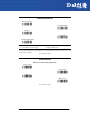
POWER SAVE...........................................................................................51
Scan Rate........................................................................................................................ 52
Sleep State/USB Suspend ......................................................................................... 52
Enter Sleep Timeout ................................................................................................... 52
Standby .......................................................................................................................... 53
READING PARAMETERS .........................................................................54
Hand-Held Operation ................................................................................................ 55
Stand Operation .......................................................................................................... 55
Hardware Trigger Signal ........................................................................................... 56
Trigger-off Timeout .................................................................................................... 56
Flash Mode .................................................................................................................... 57
Reads per Cycle ............................................................................................................ 57
Safety Time .................................................................................................................... 58
Beeper Intensity........................................................................................................... 58
Beeper Tone .................................................................................................................. 59
Beeper Type .................................................................................................................. 59
Beeper Length .............................................................................................................. 59
Good Read Spot Duration ........................................................................................ 59
Stand Recognition Beep ........................................................................................... 60
Automatic Operation Aiming Light ...................................................................... 61
Aiming System ............................................................................................................. 61
DECODING PARAMETERS ......................................................................62
Ink Spread ...................................................................................................................... 63
Overflow Control ......................................................................................................... 63
Interdigit Control......................................................................................................... 64
Decoding Safety .......................................................................................................... 64
Puzzle Solver™ .............................................................................................................. 65
CODE SELECTION ...................................................................................66
EAN/UPC Family .......................................................................................................... 68
2/5 Family ...................................................................................................................... 72
Code 39 Family ............................................................................................................ 73
Code 128 Family .......................................................................................................... 75
Code 93........................................................................................................................... 76
Codabar Family ............................................................................................................ 77
MSI.................................................................................................................................... 79
Plessey ............................................................................................................................ 80
Telepen ........................................................................................................................... 81
Delta IBM ........................................................................................................................ 82
Code 11........................................................................................................................... 83
iv
Code 16K ........................................................................................................................ 84
Code 49........................................................................................................................... 84
RSS Codes ...................................................................................................................... 85
ADVANCED FORMATTING .....................................................................86
Concatenation.............................................................................................................. 87
Advanced Formatting ............................................................................................... 90
4
REFERENCES ........................................................................................ 105
A
HOST CONFIGURATION STRINGS ........................................................ 120
B
CODE IDENTIFIER TABLE ......................................................................... 131
v
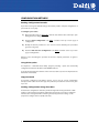
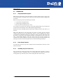
CONFIGURATION METHODS
Reading Configuration Barcodes
If you wish to change the default settings, this manual provides complete configuration of
your reader in an easy way:
To configure your reader:
1) Open the folded page in Appendix C with the hex-numeric table and keep it open
during the device configuration.
2) Read the Enter Configuration code ONCE, available at the top of each page of
configuration.
3) Modify the desired parameters in one or more sections following the procedures
given for each group.
4) Read the Exit and Save Configuration code ONCE, available at the top of each
page of configuration.
Reference notes describing the operation of the more complex parameters are given in
chapter 4.
Using DL Sm@rtSet
DL Sm@rtSet is a Windows-based utility program providing a quick and user-friendly
configuration method via the RS232 or USB-COM interfaces.
It also allows upgrading the software of the connected device (see the DL Sm@rtSet User’s
Manual for more details).
Copy Command
A previously configured reader (Master device), can be used to send its configuration
directly to other readers of the same type. The particular procedure for each device is given
in par. 4.7.
Sending Configuration Strings from Host
An alternative configuration method is provided in Appendix A using the RS232 or USB
interfaces. This method is particularly useful when many devices need to be configured
with the same settings. Batch files containing the desired parameter settings can be
prepared to configure devices quickly and easily.
vi
INTRODUCTION
1
INTRODUCTION
This manual provides all the necessary information for complete software configuration of
DelfiScan C80.
Your reader contains a built-in decoder and multi-standard interface.
It is designed for use in a wide variety of applications and environments including
commercial, office automation, retail, and light industrial applications where large
quantities of information need to be collected rapidly, easily and reliably.
It has several status indicator functions which are described in the next paragraph.
1
DELFISCAN C80
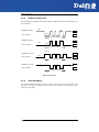
1.1
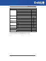
STATUS INDICATORS
Several status indicators are available depending on the type of reader: LEDs, Beeper, and
Good Read Spot (for CCD Long Range readers only). They signal several operating
conditions which are described in the tables below.
H = high tone
L = low tone
READER START-UP
Beeper
1
LLLL
Meaning
Parameters loaded correctly
H H H H
long tones
HLHL
OFF
Parameter loading error, reading or writing error in the non volatile
memory
Hardware error in EEPROM
No beeper performed when illuminator line is kept high at power on.
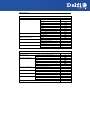
READER CONFIGURATION
Beeper
1
HHHH
L
Meaning
correct entry in Configuration mode
good read of a command
LLL
command read error
LHHHH
exit from Configuration mode
READER DATA ENTRY
Beeper
1
one beep2
LED
Good Read Spot
Meaning
ON
ON
correct read of a code in normal mode
OFF
OFF
ready to read a code
1
only the Beeper Intensity command can modify these signals.
2
the data entry good read tone is user-configurable with all the Beeper commands in the
Reading Parameters section.
2
INITIAL SETUP
2
INITIAL SETUP
2.1
INTERFACE SELECTION
Follow the procedure to configure the interface required by your application
•
•
•
•
USB Interface
RS232 Interface
Wedge Interface
Pen Emulation Interface
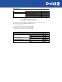
2.1.1
USB Interface Configuration
The USB interface is compatible with:
-
Windows 98 (and later)
Mac OS 8.0 (and later)
IBM POS for Windows
4690 Operating System
The USB interface is compatible with:
Windows 98 (and later)
Mac OS 8.0 (and later)
IBM POS for Windows
4690 Operating System
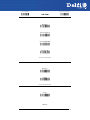
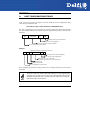
START-UP
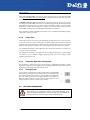
As with all USB devices, upon connection, the Host performs several checks by
communicating with the USB device. During this phase the LED on the device blinks and
normal operations are suspended. Two basic conditions must be met before the USB
device is ready to read codes, the correct USB driver must be loaded and sufficient power
must be supplied to the reader.
For all systems, the correct USB driver for the default USB-KBD interface is included in the
Host Operating System and will either be loaded automatically or will be suggested by the
O.S. and should therefore be selected from the dialog box (the first time only).
If the Host supplies sufficient power to the reader, the start-up phase ends correctly, the
LED stops blinking and the reader emits the beep OK signal.
If the Host does not supply sufficient power to the reader, a dialog box will appear on the
Host and the reader will be blocked (LED continues blinking). In this case, disconnect the
USB device cable at the Host (LED stops blinking), connect and power-up an external
supply to the USB device cable then reconnect the USB device cable to the Host and close
the dialog box. The reader emits the beep OK signal. You can now read codes. At this point
you can read the USB interface configuration code according to your application. Load
drivers from the O.S. (if requested). When configuring the USB-COM interface, the relevant
files and drivers must be installed from the USB Device Installation software which can be
downloaded from the web site: http://www.delfi.com.
The reader is ready.
3
DELFISCAN C80
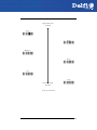
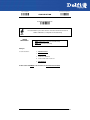
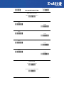
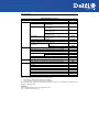
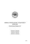
First Start-Up
Connect device to
Host with USB c able
LED blin ks
Load driver s
(if r eque st ed)
LED off
Disconnect r eader at
Host
Connect external
power supply to cable
and power up
BEEP O K
Reconnect reader
cable to Host and
close dialog box
YES
Does a dialog
box appear
ask ing w hether
Bus power is
sufficient?
NO
LED o ff - BEEP O K
Select desir ed USB
int er fac e code
L oad drivers
(if re queste d)
Read test codes.
R eader is READY
4
INITIAL SETUP
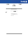
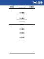
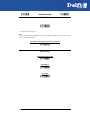
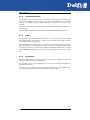
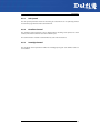
Successive start-ups will automatically recognize the previously loaded drivers. If external
power is used, verify that external power is already supplied.
Successive Start-Ups
C onnect device to
Host with USB cable
Disc on nect reader at
Host
C onn ect external
power supply to c able
and pow er up
YES
LED b links
Does a dialog
box appear
asking whether
Bus power is
sufficient?
NO
LED off - B EEP OK
BEEP OK
Reconnect reader
cable to Host and
close dialog box
Read t est codes.
Reader is R EADY
5
DELFISCAN C80
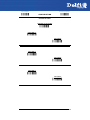
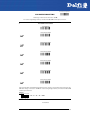
USB INTERFACE
USB-KBD
Ì$+UA03$-:Î
USB-KBD-ALT-MODE
Ì$+UA04$-@Î
USB-KBD-APPLE
Ì$+UA05$-FÎ
USB-COM*
Ì$+UA02$-4Î
USB-IBM-Table Top
Ì$+UA00$-(Î
USB-IBM-Hand Held
Ì$+UA01$-.Î
*
When configuring USB-COM, the relevant files and drivers must be installed from the
USB Device Installation software which can be downloaded from the web site: (see
http://www.delfi.com).
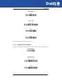
2.1.2
RS232 Interface Selection
Read the restore default code, then read the interface selection code for your application:
RESTORE DEFAULT
Ì$+$*oÎ
6
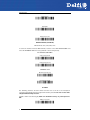
INITIAL SETUP
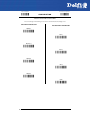
RS232 INTERFACE
Standard
Ì$+CP0$-$Î
POS SYSTEMS
Nixdorf Mode A
Ì$+CM2EC0$->Î
Fujitsu
Ì$+CM1$-ÈÎ
ICL Mode
Ì$+CM0$-ÃÎ
For POS system default settings refer to par. 4.8.
2.1.3
Wedge Interface Selection
Read the restore default code, then read the interface selection code for your application:
RESTORE DEFAULT
Ì$+$*oÎ
WEDGE INTERFACE
IBM AT or PS/2 PCs
Ì$+CP500$-aÎ
IBM XT
Ì$+CP503$-vÎ
7
DELFISCAN C80
PC Notebook
Ì$+CP505$-ÈÎ
IBM SURE1
Ì$+CP506$-$Î
IBM Terminal 3153
Ì$+CP504$-}Î
WEDGE INTERFACE (CONTINUED)
IBM Terminals 31xx, 32xx, 34xx, 37xx:
To select the interface for these IBM Terminals, read the correct KEY TRANSMISSION code.
Select the KEYBOARD TYPE if necessary (default = advanced keyboard).
KEY TRANSMISSION MODE
make-only keyboard
Ì$+CP502$-oÎ
make-break keyboard
Ì$+CP501$-hÎ
KEYBOARD TYPE
advanced keyboard
Ì$+FK1$-ÉÎ
typewriter keyboard
Ì$+FK0$-ÄÎ
ALT MODE
The following interface selection allows barcodes sent to the PC to be interpreted
correctly independently from the Keyboard Nationality used. You do not need to make
a Keyboard Nationality selection.
(default = Num Lock Unchanged). Make sure the Num Lock key on your keyboard is
ON.
IBM AT - ALT mode
Ì$+CP507$-+Î
8
INITIAL SETUP
PC Notebook - ALT mode
Ì$+CP508$-2Î
WEDGE INTERFACE (CONTINUED)
WYSE TERMINALS
ANSI Keyboard
Ì$+CP509$-9Î
PC Keyboard
Ì$+CP510$-gÎ
ASCII Keyboard
Ì$+CP511$-nÎ
VT220 style Keyboard
Ì$+CP514$-ÇÎ
DIGITAL TERMINALS
VT2xx/VT3xx/VT4xx
Ì$+CP512$-uÎ
APPLE
APPLE ADB Bus
Ì$+CP513$-|Î
2.1.4
Pen Emulation Interface Selection
Read the restore default code, then read the Pen Emulation interface selection code.
RESTORE DEFAULT
Ì$+$*oÎ
9
DELFISCAN C80
PEN EMULATION
Ì$+CP6$-BÎ
10
CONFIGURATION
3
CONFIGURATION
3
Once your reader is setup, you can change the default parameters to meet your
application needs. Refer to chapter 2 for initial configuration in order to set the default
values and select the interface for your application.
In this manual, the configuration parameters are divided into logical groups making it easy
to find the desired function based on its reference group.
The first four groups are for Standard Interface parameter configuration:
•
USB
•
RS232
•
WEDGE
•
PEN EMULATION
The following parameter groups are common to all interface applications:
DATA FORMAT parameters regard the messages sent to the Host system for all interfaces
except Pen Emulation.
POWER SAVE manages overall current consumption in the reading device.
READING PARAMETERS control various operating modes and indicator status
functioning.
DECODING PARAMETERS maintain correct barcode decoding in certain special reading
conditions.
CODE SELECTION parameters allow configuration of a personalized mix of codes, code
families and their options.
ADVANCED FORMATTING PARAMETERS allow code concatenation and advanced
formatting of messages towards the Host. It cannot be used with Pen Emulation.
11
USB PARAMETERS
~
USB-COM
~
Handshaking, Ack/Nack protocol, FIFO, Intercharacter delay, Rx timeout, Serial trigger lock
~
USB-KBD
~
Keyboard nationality, FIFO, Inter-character
delay, Inter-code delay, Control character
emulation
~
USB-IBM
~
No parameter selection required.
1.
Read the Enter Configuration code ONCE, available at the top of each page.
2.
Read configuration codes from the desired groups.
= Read the code and follow the procedure given
3.
12
= Default value
Read the Exit and Save Configuration code ONCE, available at the top of each
page.
Enter Configuration
Ì$+;Î
Exit and Save Configuration
USB-COM
Ì$-?Î
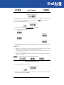
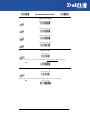
HANDSHAKING
disable
ÌCE0WÎ
hardware (RTS/CTS)
ÌCE1ZÎ
software (XON/XOFF)
ÌCE2]Î
RTS always ON
ÌCE3`Î
See par. 4.1.1 for details.
ACK/NACK PROTOCOL
disable
ÌER0sÎ
enable
ÌER1vÎ
See par. 4.1.2 for details.
FIFO
disable
ÌEC0UÎ
enable
13
Enter Configuration
Ì$+;Î
Exit and Save Configuration
USB-COM
ÌEC1XÎ
See par. 4.1.3 for details.
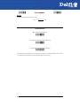
INTER-CHARACTER DELAY
delay between characters transmitted to Host
ÌCK3Î
Read 2 numbers from the table where:
00 = DELAY disabled
01-99 = DELAY from 1 to 99 milliseconds
delay disabled
14
Ì$-?Î
Enter Configuration
Ì$+;Î
Exit and Save Configuration
USB-COM
Ì$-?Î
RX TIMEOUT
timeout control in reception from Host
ÌCL5Î
Read 2 numbers from the table where:
00 = TIMEOUT disabled
01-99 = TIMEOUT from .1 to 9.9 seconds
rx timeout 5 seconds
See par. 4.1.4 for details.
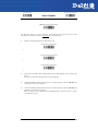
SERIAL TRIGGER LOCK
disabled
ÌCR0qÎ
enable and select characters
ÌCR1tÎ
Read 2 characters from the Hex/Numeric table in the range 00-FE where:
−
First Character enables device trigger
−
Second Character inhibits device trigger until the first character is received again.
15
Enter Configuration
Ì$+;Î
Exit and Save Configuration
USB-KBD
Ì$-?Î
KEYBOARD NATIONALITY
Not Available for USB-KBD-ALT-MODE Interface
This parameter default value is restored through the Interface Selection code and not Restore Default.
Belgian
ÌFJ7yÎ
English
ÌFJ4pÎ
French
ÌFJ2jÎ
German
ÌFJ3mÎ
Italian
ÌFJ1gÎ
Japanese
ÌFJ8|Î
Spanish
ÌFJ6vÎ
Swedish
ÌFJ5sÎ
USA
ÌFJ0dÎ
FIFO
disable
ÌEC0UÎ
enable
ÌEC1XÎ
See par. 4.1.3 for details.
16
Enter Configuration
Ì$+;Î
Exit and Save Configuration
USB-KBD
Ì$-?Î
INTER-CHARACTER DELAY
delay between characters transmitted to Host
ÌCK3Î
Read 2 numbers from the table where:
00 = DELAY disabled
01-99 = DELAY from 1 to 99 milliseconds
delay disabled
INTER-CODE DELAY
delay between codes transmitted to Host
ÌFG.Î
Read 2 numbers from the table where:
00 = DELAY disabled
01-99 = DELAY from 1 to 99 seconds
delay disabled
17
Enter Configuration
Ì$+;Î
Exit and Save Configuration
USB-KBD
CONTROL CHARACTER EMULATION
CTRL+ Shift + Key
ÌFO0nÎ
CTRL + Key
ÌFO1qÎ
18
Ì$-?Î
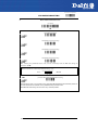
RS232 PARAMETERS
~
BAUD RATE
~
~
PARITY
~
~
DATA BITS
~
~
STOP BITS
~
~
HANDSHAKING
~
~
ACK/NACK PROTOCOL
~
~
FIFO
~
~
INTER-CHARACTER DELAY
~
~
RX TIMEOUT
~
~
SERIAL TRIGGER LOCK
~
1.
Read the Enter Configuration code ONCE, available at the top of each page.
2.
Read configuration codes from the desired groups.
= Read the code and follow the procedure given
3.
= Default value
Read the Exit and Save Configuration code ONCE, available at the top of each
page.
19
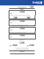
Enter Configuration
Ì$+;Î
Exit and Save Configuration
RS232
Ì$-?Î
BAUD RATE
300 baud
ÌCD1XÎ
600 baud
ÌCD2[Î
1200 baud
ÌCD3^Î
2400 baud
ÌCD4aÎ
4800 baud
ÌCD5dÎ
9600 baud
ÌCD6gÎ
19200 baud
ÌCD7jÎ
38400 baud
ÌCD8mÎ
20
Enter Configuration
Ì$+;Î
Exit and Save Configuration
RS232
Ì$-?Î
PARITY
none
ÌCC0SÎ
even parity
ÌCC1VÎ
odd parity
ÌCC2YÎ
DATA BITS
7 bits
ÌCA0OÎ
8 bits
ÌCA1RÎ
9 bits
ÌCA2UÎ
STOP BITS
1 stop bit
ÌCB0QÎ
2 stop bits
ÌCB1TÎ
21
Enter Configuration
Ì$+;Î
Exit and Save Configuration
RS232
HANDSHAKING
disable
ÌCE0WÎ
hardware (RTS/CTS)
ÌCE1ZÎ
software (XON/XOFF)
ÌCE2]Î
RTS always ON
ÌCE3`Î
See par. 4.1.1 for details.
ACK/NACK PROTOCOL
disable
ÌER0sÎ
enable
ÌER1vÎ
See par. 4.1.2 for details.
22
Ì$-?Î
Enter Configuration
Ì$+;Î
Exit and Save Configuration
RS232
Ì$-?Î
FIFO
disable
ÌEC0UÎ
enable
ÌEC1XÎ
See par. 4.1.3 for details.
23
Enter Configuration
Ì$+;Î
Exit and Save Configuration
RS232
INTER-CHARACTER DELAY
delay between characters transmitted to Host
ÌCK3Î
Read 2 numbers from the table where:
00 = DELAY disabled
01-99 = DELAY from 1 to 99 milliseconds
delay disabled
RX TIMEOUT
timeout control in reception from Host
ÌCL5Î
Read 2 numbers from the table where:
00 = TIMEOUT disabled
01-99 = TIMEOUT from .1 to 9.9 seconds
rx timeout 5 seconds
See par. 4.1.4 for details.
24
Ì$-?Î
Enter Configuration
Ì$+;Î
Exit and Save Configuration
RS232
Ì$-?Î
SERIAL TRIGGER LOCK
disabled
ÌCR0qÎ
enable and select characters
ÌCR1tÎ
Read 2 characters from the Hex/Numeric table in the range 00-FE where:
−
First Character enables device trigger
−
Second Character inhibits device trigger until the first character is received again.
25
WEDGE PARAMETERS
~
KEYBOARD NATIONALITY
~
~
CAPS LOCK
~
~
CAPS LOCK
AUTO-RECOGNITION
~
~
NUM LOCK
~
~
INTER-CHARACTER DELAY
~
~
INTER-CODE DELAY
~
~
CONTROL CHARACTER
EMULATION
~
~
KEYBOARD SETTING
~
1.
Read the Enter Configuration code ONCE, available at the top of each page.
2.
Read configuration codes from the desired groups.
= Read the code and follow the procedure given
3.
.
26
= Default value
Read the Exit and Save Configuration code ONCE, available at the top of
each page.
Enter Configuration
Ì$+;Î
Exit and Save Configuration
Ì$-?Î
WEDGE
KEYBOARD NATIONALITY
This parameter default value is restored through the Interface Selection code and not Restore Default.
Belgian
ÌFJ7yÎ
English
ÌFJ4pÎ
French
ÌFJ2jÎ
German
ÌFJ3mÎ
Italian
ÌFJ1gÎ
Spanish
ÌFJ6vÎ
Swedish
ÌFJ5sÎ
USA
ÌFJ0dÎ
The Japanese Keyboard Nationality selection is valid only for IBM AT compatible PCs.
Japanese
ÌFJ8|Î
27
Enter Configuration
Ì$+;Î
Exit and Save Configuration
WEDGE
Ì$-?Î
CAPS LOCK
caps lock OFF
ÌFE0ZÎ
caps lock ON
ÌFE1]Î
Select the appropriate code to match your keyboard caps lock status.
Note:
Caps lock manual configuration is ignored when Caps Lock Auto-Recognition is enabled.
For PC Notebook interface selections, the caps lock status is automatically recognized,
therefore this command is not necessary.
CAPS LOCK AUTO-RECOGNITION (IBM AT COMPATIBLE ONLY)
disable
ÌFP0pÎ
enable
ÌFP1sÎ
28
Enter Configuration
Ì$+;Î
Exit and Save Configuration
WEDGE
Ì$-?Î
NUM LOCK
toggle num lock
ÌFL1kÎ
num lock unchanged
ÌFL0hÎ
This selection is used together with the Alt Mode interface selection for AT or Notebook PCs.
It changes the way the Alt Mode procedure is executed, therefore it should be set as follows:
•
if your keyboard Num Lock is normally on use num lock unchanged
•
if your keyboard Num Lock is normally off use toggle num lock
In this way the device will execute the Alt Mode procedure correctly for your application.
INTER-CHARACTER DELAY
delay between characters transmitted to Host
ÌCK3Î
Read 2 numbers from the table where:
00 = DELAY disabled
01-99 = DELAY from 1 to 99 milliseconds
delay disabled
INTER-CODE DELAY
delay between codes transmitted to Host
ÌFG.Î
Read 2 numbers from the table where:
00 = DELAY disabled
01-99 = DELAY from 1 to 99 seconds
29
Enter Configuration
Ì$+;Î
Exit and Save Configuration
WEDGE
delay disabled
CONTROL CHARACTER EMULATION
CTRL+ Shift + Key
ÌFO0nÎ
CTRL + Key
ÌFO1qÎ
30
Ì$-?Î
Enter Configuration
Exit and Save Configuration
Ì$+;Î
WEDGE
Ì$-?Î
KEYBOARD SETTING
ALPHANUMERIC KEYBOARD SETTING
The reader can be used with terminals or PCs with various keyboard types and nationalities through a
simple keyboard setting procedure.
The type of computer or terminal must be selected before activating the keyboard setting command.
Keyboard setting consists of communicating to the reader how to send data corresponding to the
keyboard used in the application. The keys must be set in a specific order.
Press and release a key to set it.
Some characters may require more than one key pressed simultaneously during normal use (refer to
the manual of your PC or terminal for keyboard use). The exact sequence must be indicated to the
reader in this case pressing and releasing the different keys.
Example:
If one has to press the "Shift" and "4" keys simultaneously on the keyboard to transmit the character
"$" to the video, to set the "$", press and release "Shift" then press and release "4".
Each pressed and released key must generate an acoustic signal on the reader, otherwise repress the
key. Never press more than one key at the same time, even if this corresponds to the normal use of
your keyboard.
Press "Backspace" to correct a wrong key entry. In this case the reader emits 2 beeps.
Note: "CAPS LOCK" and "NUM LOCK" must be off before starting the keyboard setting
procedure. "SHIFT" must be repressed for each character and cannot be substituted by "CAPS
LOCK".
setting the alphanumeric keyboard
ÌFB0TÎ
Read the code above.
Press the keys shown in the following table according to their numerical order:
31
Enter Configuration
Exit and Save Configuration
Ì$+;Î
Ì$-?Î
WEDGE
Some ASCII characters may be missing as this depends on the type of keyboard: these are generally
particular characters relative to the various national symbologies. In this case:
•
The first 4 characters (Shift, Alt, Ctrl, and Backspace) can only be substituted with keys not
used, or substituted with each other.
•
characters can be substituted with other single symbols (e.g. "SPACE") even if not included in the
barcode set used.
•
characters can be substituted with others corresponding to your keyboard.
The reader signals the end of the procedure with 2 beeps indicating the keys have been
registered.
01 : Shift
02 : Alt
03 : Ctrl
04 : Backspace
05 : SPACE
06 : !
07 : "
08 : #
09 : $
10 : %
11 : &
12 : '
13 : (
14 : )
15 : *
16 : +
17 : ,
18 : 19 : .
20 : /
21 : 0
22 : 1
23 : 2
24 : 3
25 : 4
26 : 5
27 : 6
32
28 : 7
29 : 8
30 : 9
31 : :
32 : ;
33 : <
34 : =
35 : >
36 : ?
37 : @
38 : A
39 : B
40 : C
41 : D
42 : E
43 : F
44 : G
45 : H
46 : I
47 : J
48 : K
49 : L
50 : M
51 : N
52 : O
53 : P
54 : Q
55 : R
56 : S
57 : T
58 : U
59 : V
60 : W
61 : X
62 : Y
63 : Z
64 : [
65 : \
66 : ]
67 : ^
68 : _ (underscore)
69 : `
70 : {
71 : |
72 : }
73 : ~
74 : DEL
PEN EMULATION
~
OPERATING MODE
~
~
MINIMUM OUTPUT PULSE
~
~
CONVERSION TO CODE 39
~
~
OVERFLOW
~
~
OUTPUT LEVEL
~
~
IDLE LEVEL
~
~
INTER-BLOCK DELAY
~
1.
Read the Enter Configuration code ONCE, available at the top of each page.
2.
Read configuration codes from the desired groups.
3.
= Default value
Read the Exit and Save Configuration code ONCE, available at the top of each
page.
33
PEN EMULATION
The operating mode parameters are complete commands and do not require reading the Enter
and Exit configuration codes.
OPERATING MODE
interpret mode
Ì$]8Î
Interprets commands without sending them to the decoder.
transparent mode
Ì$[4Î
Sends commands to the decoder without interpreting them.
34
MINIMUM OUTPUT PULSE
high resolution code
emulation
200 μs
ÌDG0\Î
400 μs
ÌDG1_Î
600 μs
ÌDG2bÎ
800 μs
ÌDG3eÎ
1 ms
ÌDG4hÎ
1.2 ms
low resolution code
emulation
ÌDG5kÎ
See par. 4.2.1 for details.
35
Enter Configuration
Ì$+;Î
Exit and Save Configuration
PEN EMULATION
CONVERSION TO CODE 39
► disable conversion to Code 39
ÌDA0PÎ
Transmits codes in their original format.
enable conversion to Code 39
ÌDA1SÎ
Converts codes read into Code 39 format.
See par. 4.2.2 for details.
OVERFLOW
narrow
ÌDH0^Î
medium
ÌDH1aÎ
wide
ÌDH2dÎ
See par. 4.2.3 for details.
36
Ì$-?Î
OUTPUT LEVEL
normal
(white = logic level 0)
ÌDD0VÎ
inverted
(white = logic level 1)
ÌDD1YÎ
See par. 4.2.4 for details.
IDLE LEVEL
normal
(black level)
ÌDE0XÎ
inverted
(white level)
ÌDE1[Î
See par. 4.2.4 for details.
37
Enter Configuration
Ì$+;Î
Exit and Save Configuration
PEN EMULATION
INTER-BLOCK DELAY
delay between character blocks transmitted to Host
ÌCK3Î
Read 2 numbers from the table where:
00 = DELAY disabled
01-99 = DELAY from .1 to 9.9 seconds
delay disabled
See par. 4.2.5 for details.
38
Ì$-?Î
DATA FORMAT
NOT FOR PEN INTERFACES
~
CODE IDENTIFIER
~
~
CUSTOM CODE IDENTIFIER
~
~
HEADER
~
~
TERMINATOR
~
~
FIELD ADJUSTMENT
~
~
FIELD ADJ. CHARACTER
~
~
CODE LENGTH TX
~
~
CHARACTER REPLACEMENT
~
1.
Read the Enter Configuration code ONCE, available at the top of each page.
2.
Read configuration codes from the desired groups.
= Read the code and follow the procedure given
3.
= Default value
Read the Exit and Save Configuration code ONCE, available at the top of each
page.
39
DATA FORMAT
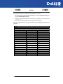
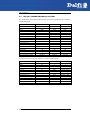
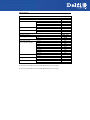
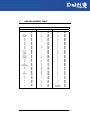
CODE IDENTIFIER TABLE
CODE
2/5 interleaved
2/5 industrial
2/5 normal 5 bars
2/5 matrix 3 bars
EAN 8
EAN 13
UPC A
UPC E
EAN 8 with 2 ADD ON
EAN 8 with 5 ADD ON
EAN 13 with 2 ADD ON
EAN 13 with 5 ADD ON
UPC A with 2 ADD ON
UPC A with 5 ADD ON
UPC E with 2 ADD ON
UPC E with 5 ADD ON
Code 39
Code 39 Full ASCII
CODABAR
ABC CODABAR
Code 128
EAN 128
ISBT 128
Code 93
CIP/39
CIP/HR
Code 32
MSI
Plessey Standard
Plessey Anker
Telepen
Delta IBM
Code 11
Code 16K
Code 49
RSS Expanded Linear and Stacked
RSS Limited
RSS 14 Linear and Stacked
40
AIM STANDARD
DATALOGIC STANDARD
]Iy
]Xy
]Sy
]Xy
]E4
]E0
]Xy
]Xy
]E5
]E6
]E1
]E2
]Xy
]Xy
]Xy
]Xy
]Ay
]Ay
]Fy
]Xy
]Cy
]Cy
] C4
]Gy
]Xy
]Xy
]Xy
]My
]P0
]P1
]X0
]X0
]Hy
]K0
]Ty
]e0
]e0
]e0
N
P
O
Q
A
B
C
D
J
K
L
M
F
G
H
I
V
W
R
S
T
k
f
U
Y
e
X
Z
a
o
d
c
b
p
q
t
v
u
Custom
DATA FORMAT
AIM standard identifiers are not defined for all codes: the X identifier is assigned to the code for which
the standard is not defined. The y value depends on the selected options (check digit tested or not,
check digit tx or not, etc.).
•
When customizing the Datalogic Standard code identifiers, 1 or 2 identifier characters can be
defined for each code type. If only 1 identifier character is required, the second character must
be selected as FF (disabled).
•
The code identifier can be singly disabled for any code by simply selecting FF as the first
identifier character.
•
Write in the Custom character identifiers in the table above for your records.
41
Enter Configuration
Ì$+;Î
Exit and Save Configuration
DATA FORMAT
CODE IDENTIFIER
disable
ÌEB0SÎ
Datalogic standard
ÌEB1VÎ
AIM standard
ÌEB2YÎ
custom
ÌEB3\Î
42
Ì$-?Î
Enter Configuration
Ì$+;Î
Exit and Save Configuration
Ì$-?Î
DATA FORMAT
CUSTOM CODE IDENTIFIER
define custom code identifier(s)
ÌEH/Î
c Read the above code.
(Code Identifiers default to Datalogic standard, see table on previous page).
d
Select the code type from the code table in Appendix B for the identifier you want to change.
e You can define 1 or 2 identifier characters for each code type. If only 1 identifier character is
required, the second character must be selected as FF (disabled). Read the hexadecimal value
corresponding to the character(s) you want to define as identifiers for the code selected in step d:
valid characters are in the range 00-FD.
Example:
To define Code 39 Code Identifier = @
define custom code identifier(s)
Read
ÌEH/Î
Code 39
+
ÌVWÎ
+
40
+
FF
43
Enter Configuration
Ì$+;Î
Exit and Save Configuration
Ì$-?Î
DATA FORMAT
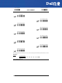
HEADER
no header
ÌEA00*Î
one character header
ÌEA01.Î
two character header
ÌEA022Î
three character header
ÌEA036Î
four character header
ÌEA04:Î
five character header
ÌEA05>Î
six character header
ÌEA06BÎ
seven character header
ÌEA07FÎ
eight character header
ÌEA08JÎ
After selecting one of the desired Header codes, read the character(s) from the HEX table. Valid characters are in the
range 00-FE.
Example:
four character header
+ 41 + 42 + 43 + 44 = Header ABCD
For more details see par. 4.2.6.
44
Enter Configuration
Ì$+;Î
Exit and Save Configuration
DATA FORMAT
Ì$-?Î
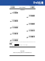
TERMINATOR
no terminator
ÌEA10-Î
one character terminator
ÌEA111Î
two character terminator
ÌEA125Î
three character terminator
ÌEA139Î
four character terminator
ÌEA14=Î
five character terminator
ÌEA15AÎ
six character terminator
ÌEA16EÎ
seven character terminator
ÌEA17IÎ
eight character terminator
ÌEA18MÎ
After selecting one of the desired Header codes, read the character(s) from the HEX table. Valid characters are in the
range 00-FE.
Example:
two character terminator
+ 0D + 0A = Terminator CR LF
For more details see par. 4.2.6.
SPECIAL KEYS
Available only for Wedge IBM AT-PS/2 and USB-KBD Interfaces
45
Enter Configuration
Ì$+;Î
Exit and Save Configuration
DATA FORMAT
Ì$-?Î
It is necessary to define each Special Key by following the procedure given in par. Fejl!
Henvisningskilde ikke fundet..
NOTE
Select one or more of the following Special Keys according to your needs.
Special Key 1
Ì9CÄÎ
Special Key 2
Ì9DÆÎ
Special Key 3
Ì9EÈÎ
Special Key 4
Ì9FÊÎ
Special Key 5
ÌA0bÎ
46
Enter Configuration
Exit and Save Configuration
Ì$+;Î
Ì$-?Î
DATA FORMAT
FIELD ADJUSTMENT
disable field adjustment
ÌEF0[Î
Field adjustment allows a number of characters n, to be added to or subtracted from the barcode
read. The adjustment can be different for each enabled code type. To define the field adjustment:
c Read the enable field adjustment code:
enable field adjustment
ÌEF+Î
d Select the code type from the Code Identifier Table in Appendix B.
e Select the type of adjustment to perform:
right addition
Ì01Î
left addition
Ì12Î
right deletion
Ì23Î
left deletion
Ì34Î
f Read a number in the range 01 - 32 from the Hex/Numeric Table to define how many characters
to add or delete:
Conditions:
•
Adjustment is only performed on the barcode data, the Code Identifier and Code Length
Transmission fields are not modified by the field adjustment parameter.
•
If the field setting would subtract more characters than exist in the barcode, the subtraction will
take place only to code length 0.
•
You can set up to a maximum of 10 different field adjustments on the same barcode family or on
different barcode families.
Example: To add 4 characters to the right of Standard Code 39 Codes:
enable field adjustment
Read
ÌEF+Î
Code 39
+
ÌVWÎ
right addition
+
Ì01Î
+
04
FIELD ADJUSTMENT CHARACTER
c Read the field adjustment character code:
field adjustment character
ÌEG-Î
d Read the hexadecimal value corresponding to the character you want to use for field adjustment.
Valid characters are in the range 00-FE.
47
Enter Configuration
Ì$+;Î
Exit and Save Configuration
DATA FORMAT
Ì$-?Î
Example:
To define the field adjustment character = A:
field adjustment character
Read
+ 41
CODE LENGTH TX
code length not transmitted
ÌEE0YÎ
code length transmitted in variable-digit format
ÌEE1\Î
code length transmitted in fixed 4-digit format
ÌEE2_Î
The code length is transmitted in the message after the Headers and Code Identifier characters. The
code length is calculated after performing any field adjustment operations.
48
Enter Configuration
Ì$+;Î
Exit and Save Configuration
DATA FORMAT
Ì$-?Î
CHARACTER REPLACEMENT
disable character replacement
ÌEO0mÎ
This parameter allows up to three characters to be replaced from the barcode read. These
substitutions are stored in memory. To define each character replacement:
c
Read one of the following character replacement codes:
first character replacement
ÌEO1pÎ
second character replacement
ÌEO2sÎ
third character replacement
ÌEO3vÎ
d
From the Code Identifier Table in Appendix B, read the Code Identifier for the desired code
family.
0 = character replacement will be effective for all code families.
e
From the Hex/Numeric Table read two characters corresponding to the Hex value (00-FE) which
identifies the character to be replaced.
f
From the Hex/Numeric Table read two characters corresponding to the Hex value (00-FE) which
identifies the new character to replace.
FF = the character to be replaced will be substituted with no character, that is, it will be
removed from the code.
49
Enter Configuration
Exit and Save Configuration
Ì$+;Î
Ì$-?Î
DATA FORMAT
Example:
The following strings define:
1.
First Character Replacement: substitution in Code 39 barcodes of all occurrences of the 0 character
with the 1 character.
2.
Second Character Replacement: substitution in Code 39 barcodes of all occurrences of the A
character with the B character.
first character replacement
Code 39
ÌEO1pÎ + ÌVWÎ +
ASCII characters corresponding to
the HEX value for character 0
30
ASCII characters corresponding to
the HEX value for character 1
+
31
For Code 39 codes containing the string "0123", the contents transmitted will be "1123".
second character
replacement
Code 39
ÌEO2sÎ + ÌVWÎ +
ASCII characters corresponding to
the HEX value for character A
41
ASCII characters corresponding to
the HEX value for character B
+
42
For Code 39 codes containing the string "ABCD", the contents transmitted will be "BBCD".
50
POWER SAVE
~
SCAN RATE
~
~
SLEEP STATE/USB SUSPEND
~
~
ENTER SLEEP TIMEOUT
~
~
STANDBY
~
1.
Read the Enter Configuration code ONCE, available at the top of each page.
2.
Read configuration codes from the desired groups.
= Read the code and follow the procedure given
3.
= Default value
Read the Exit and Save Configuration code ONCE, available at the top of each
page.
51
Enter Configuration
Ì$+;Î
Exit and Save Configuration
POWER SAVE
Ì$-?Î
SCAN RATE
CCD Readers ONLY
quarter
ÌBT0tÎ
half
ÌBT1wÎ
maximum
ÌBT2zÎ
A lower scan rate reduces power consumption but can lengthen reading response time.
SLEEP STATE/USB SUSPEND
ONLY Devices with Button/Trigger
disable
ÌBQ0nÎ
enable
ÌBQ1qÎ
See par. 4.3.1 for details.
ENTER SLEEP TIMEOUT
ONLY Devices with Button/Trigger
enter sleep timeout
ÌBR@Î
Read 2 numbers in the range 00-99:
00 = Enter Sleep state immediately
01-99 = corresponds to a max. 9.9 sec. delay before entering the
Sleep state.
See par. 4.3.2 for details.
52
Enter Configuration
Ì$+;Î
Exit and Save Configuration
POWER SAVE
Ì$-?Î
STANDBY
ONLY for CCD Devices
disable
ÌBM1iÎ
optimize for reading speed
enable
ÌBM0fÎ
optimize for low power consumption
See par. 4.3.3 for details.
53
READING PARAMETERS
~
HAND-HELD OPERATION
~
~
STAND OPERATION
~
~
TRIGGER SIGNAL
~
~
TRIGGER-OFF TIMEOUT
~
~
FLASH MODE
~
~
READS PER CYCLE
~
~
SAFETY TIME
~
~
BEEPER INTENSITY
~
~
BEEPER TONE
~
~
BEEPER TYPE
~
~
BEEPER LENGTH
~
~
GOOD READ SPOT DURATION
~
~
STAND RECOGNITION BEEP
~
~
AUTOMATIC OPERATION AIMING
LIGHT
~
~
AIMING SYSTEM
~
1.
Read the Enter Configuration code ONCE, available at the top of each page.
2.
Read configuration codes from the desired groups.
= Read the code and follow the procedure given
3.
54
= Default value
Read the Exit and Save Configuration code ONCE, available at the top of each
page.
HAND-HELD OPERATION
hardware trigger
ÌBK1eÎ
software trigger
ÌBK0bÎ
always on
ÌBK3kÎ
♣ automatic
ÌBK2hÎ
* hardware trigger ready
ÌBK4nÎ
= default value for devices with trigger
= default value for devices without trigger
* = only for CCD readers with trigger
♣ = only for CCD readers
For Automatic Hand-Held or Stand Operation, the Safety Time parameter is forced to no code
consecutive reading (00).
See par. 4.4.1 for details
STAND OPERATION
ONLY Devices with Stand Recognition Beep
hardware trigger
ÌBU3ÃÎ
software trigger
ÌBU1yÎ
always on
ÌBU2|Î
♣ automatic
ÌBU0vÎ
See par. 4.4.1 for details
55
Enter Configuration
Ì$+;Î
Exit and Save Configuration
READING PARAMETERS
Ì$-?Î
HARDWARE TRIGGER SIGNAL
ONLY Devices with Button/Trigger
trigger active level
ÌBA0NÎ
trigger active pulse
ÌBA1QÎ
See par. 4.4.2 for details
TRIGGER-OFF TIMEOUT
ONLY Devices with Button/Trigger
trigger-off timeout
ÌBD$Î
Read 2 numbers in the range 00-99:
00 = disables the trigger-off timeout
01-99 = corresponds to a max. 99-sec. delay after the trigger press to
allow the reader to turn off automatically.
trigger-off timeout disabled
See par. 4.4.3 for details.
56
Enter Configuration
Ì$+;Î
Exit and Save Configuration
READING PARAMETERS
Ì$-?Î
FLASH MODE
"FLASH" ON duration
ÌBB0PÎ
"FLASH" OFF duration
ÌBB1SÎ
Read 2 numbers in the range 01-99:
01 to 99 = from .1 to 9.9 seconds.
Flash-ON = 1 sec. Flash-OFF = 0.6 sec
READS PER CYCLE
one read per cycle
ÌBC0RÎ
multiple reads per cycle
ÌBC1UÎ
See par. 4.4.4 for details.
57
Enter Configuration
Ì$+;Î
Exit and Save Configuration
READING PARAMETERS
Ì$-?Î
SAFETY TIME
safety time
ÌBE&Î
Limits same code consecutive reading.
Read 2 numbers in the range 00-99:
00 = no same code consecutive reading until reader is removed
(no decoding) for at least 400 ms.
01-99 = timeout from .1 to 9.9 seconds before a consecutive read on
same code.
safety time = 0.5 sec
See par. 4.4.5 for details.
BEEPER INTENSITY
beeper off *
ÌBG0ZÎ
low intensity
ÌBG1]Î
medium intensity
ÌBG2`Î
high intensity
ÌBG3cÎ
*
58
This sets the beeper OFF for data entry, while for all other beeper signals it has the meaning “very
low intensity”. The Beeper Intensity parameter is effective for all operating conditions described in
par. 1.1.
Enter Configuration
Ì$+;Î
Exit and Save Configuration
READING PARAMETERS
Ì$-?Î
BEEPER TONE
tone 1
ÌBH0\Î
tone 2
ÌBH1_Î
tone 3
ÌBH2bÎ
tone 4
ÌBH3eÎ
BEEPER TYPE
monotone
ÌBJ0`Î
bitonal
ÌBJ1cÎ
BEEPER LENGTH
long
ÌBI0^Î
short
ÌBI1aÎ
GOOD READ SPOT DURATION
CCD Long Range Readers ONLY
disable
ÌBV0xÎ
short
59
Enter Configuration
Ì$+;Î
Exit and Save Configuration
READING PARAMETERS
Ì$-?Î
ÌBV1{Î
medium
ÌBV2~Î
long
ÌBV3ÅÎ
STAND RECOGNITION BEEP
ONLY Readers with Stand Recognition
disable
ÌBa0'Î
enable
ÌBa1*Î
60
Enter Configuration
Ì$+;Î
Exit and Save Configuration
READING PARAMETERS
Ì$-?Î
AUTOMATIC OPERATION AIMING LIGHT
CCD Long Range Readers ONLY
disable
ÌBb0)Î
enable
ÌBb1,Î
See par. 4.4.6 for details.
AIMING SYSTEM
Laser Readers ONLY
disable
ÌBX0|Î
300 ms
ÌBX1ÃÎ
500 ms
ÌBX2ÆÎ
1 sec
ÌBX3ÉÎ
See par. 4.4.7 for details.
61
DECODING PARAMETERS
~
INK SPREAD
~
~
OVERFLOW CONTROL
~
~
INTERDIGIT CONTROL
~
~
DECODING SAFETY
~
~
PUZZLE SOLVER™
~
Before changing these parameter values read the descriptions in
par. 4.5.
CAUTION
1.
2.
3.
62
Read the Enter Configuration code ONCE, available at the top of each page.
Read configuration codes from the desired groups.
= Default value
Read the Exit and Save Configuration code ONCE, available at the top of each
page.
Enter Configuration
Ì$+;Î
Exit and Save Configuration
DECODING PARAMETERS
Ì$-?Î
INK SPREAD
disable
ÌAX0{Î
enable
ÌAX1~Î
See par. 4.5.1 for details.
OVERFLOW CONTROL
disable
ÌAW1|Î
enable
ÌAW0yÎ
See par. 4.5.2 for details.
63
Enter Configuration
Exit and Save Configuration
Ì$+;Î
Ì$-?Î
DECODING PARAMETERS
INTERDIGIT CONTROL
disable
ÌAV0wÎ
enable
ÌAV1zÎ
See par. 4.5.3 for details.
DECODING SAFETY
one read
ÌED0WÎ
(decoding safety disabled)
two reads
ÌED1ZÎ
three reads
ÌED2]Î
four reads
ÌED3`Î
Required number of good reads before accepting code.
64
Enter Configuration
Exit and Save Configuration
Ì$+;Î
DECODING PARAMETERS
Ì$-?Î
PUZZLE SOLVER™
disable
ÌAU0uÎ
enable
ÌAU1xÎ
In the case of damaged or poorly printed codes, this parameter allows reading multiple parts of the
single code to reconstruct it.
To read codes using this technology, simply move the reader over the code so that each line of the
code is scanned.
Conditions:
•
This parameter is only valid for the following codes:
EAN 8
without Add-on
EAN 13
without Add-on
Code 128
Code 39
UPC A
without Add-on
•
For Code 39, Check digit control without transmission is forced.
•
PuzzleSolver™ is disabled when code ISBT 128 is enabled.
65
CODE SELECTION
~
~
~
~
~
~
~
~
~
~
~
~
~
~
EAN/UPC FAMILY
2/5 FAMILY
CODE 39 FAMILY
CODE 128 FAMILY
CODABAR FAMILY
CODE 93
MSI
PLESSEY
TELEPEN
DELTA IBM
CODE 11
CODE 16K
CODE 49
RSS CODES
~
~
~
~
~
~
~
~
~
~
~
~
~
~
1.
Read the Enter Configuration code ONCE, available at the top of each page.
2.
Read configuration codes from the desired groups.
= Read the code and follow the procedure given
3.
66
= Default value
Read the Exit and Save Configuration code ONCE, available at the top of each
page.
Enter Configuration
Exit and Save Configuration
Ì$+;Î
CODE SELECTION
Ì$-?Î
DISABLES ALL CODE FAMILIES
ÌAZ0ÃÎ
The reader allows up to 5 code selections. This does not limit the number of
CODES enabled to 5, as it depends on the code family.
NOTE
SINGLE
SELECTIONS =
•
ONE combination code from the EAN family
•
ONE code from the 2/5 family
Example
5 code selections:
1. 2/5 Interleaved
2. 2/5 Industrial
3. Code 128 + EAN 128
4. Code 39 Full ASCII + Code 32
5. UPC A/UPC E
In this section all SINGLE code selections are underlined and in bold.
67
Enter Configuration
Exit and Save Configuration
Ì$+;Î
CODE SELECTION
Ì$-?Î
EAN/UPC FAMILY
disable the family
ÌAA0MÎ
c Read the desired family code
Note:
Since the EAN/UPC without ADD ON code selection is enabled by default, to correctly enable another
selection, first disable the family.
EAN 8/EAN 13/UPC A/UPC E with and without ADD ON
ÌAA8eÎ
WITHOUT ADD ON
EAN 8/EAN 13/UPC A/UPC E
ÌAA1PÎ
EAN 8/EAN 13
ÌAA3VÎ
UPC A/UPC E
ÌAA4YÎ
68
Enter Configuration
Ì$+;Î
Exit and Save Configuration
CODE SELECTION
Ì$-?Î
WITH ADD ON 2 AND 5
EAN 8/EAN 13/UPC A/UPC E
ÌAA5\Î
EAN 8/EAN 13
ÌAA6_Î
UPC A/UPC E
ÌAA7bÎ
WITH ADD ON 2 ONLY
EAN 8/EAN 13
ÌAAK7Î
UPC A/UPC E
ÌAAM=Î
WITH ADD ON 5 ONLY
EAN 8/EAN 13
ÌAAL:Î
UPC A/UPC E
ÌAAN@Î
69
Enter Configuration
Exit and Save Configuration
Ì$+;Î
Ì$-?Î
CODE SELECTION
EAN/UPC CHECK DIGIT TX SELECTIONS
For each code type in this family you can choose to transmit the check digit or not
CHECK DIGIT TRANSMISSION
NO CHECK DIGIT TRANSMISSION
EAN 8
ÌAAG1oÎ
EAN 8
ÌAAG0kÎ
EAN 13
ÌAAH1rÎ
EAN 13
ÌAAH0nÎ
UPC A
ÌAAI1uÎ
UPC A
ÌAAI0qÎ
UPC E
ÌAAJ1xÎ
UPC E
ÌAAJ0tÎ
70
Enter Configuration
Ì$+;Î
Exit and Save Configuration
CODE SELECTION
Ì$-?Î
CONVERSION OPTIONS
UPC E to UPC A conversion
ÌAAAÄÎ
UPC E to EAN 13 conversion
ÌAABÇÎ
UPC A to EAN 13 conversion
ÌAACÊÎ
EAN 8 to EAN 13 conversion
ÌAAD"Î
Enable only ISBN conversion
ÌAP1nÎ
Enable only ISSN conversion
ÌAP2qÎ
Enable both ISBN and ISSN conversion
ÌAP3tÎ
Disable both ISBN and ISSN conversion
ÌAP0kÎ
71
Enter Configuration
Ì$+;Î
Exit and Save Configuration
Ì$-?Î
CODE SELECTION
2/5 FAMILY
disables the family
ÌAC0QÎ
c Read the desired family code
d Read a check digit selection
Interleaved 2/5
ÌAC1TÎ
CHECK DIGIT TABLE
no check digit control
Ì12Î
Normal 2/5 (5 Bars)
ÌAC2WÎ
check digit control and transmission
Ì23Î
Industrial 2/5 (IATA)
ÌAC3ZÎ
check digit control without transmission
Ì34Î
Matrix 2/5 (3 Bars)
ÌAC4]Î
The pharmaceutical code below is part of
the 2/5 family but has no check digit or code
length selections.
Code CIP/HR
ÌAC5`Î
French pharmaceutical code
72
e Read 4 numbers for the code length
where:
−
First 2 digits = minimum code length.
−
Second 2 digits = maximum code
length.
The maximum
characters.
code
length
is
99
The minimum code length must always be
less than or equal to the maximum.
Examples:
0199 = variable from 1 to 99 digits in
the code.
1010 = 10 digit code length only.
Enter Configuration
Exit and Save Configuration
Ì$+;Î
CODE SELECTION
Ì$-?Î
CODE 39 FAMILY
disables the family
ÌAB0OÎ
c Read the desired family code
d Read a check digit selection
CHECK DIGIT TABLE
Standard Code 39
ÌAB1RÎ
Full ASCII Code 39
ÌAB2UÎ
no check digit control
Ì12Î
check digit control
and transmission
Ì23Î
check digit control
without transmission
Ì34Î
The pharmaceutical codes below are part of the Code 39 family but have no check digit selections.
Code CIP39
ÌAB3XÎ
French pharmaceutical code
Code 32
ÌAB4[Î
Italian pharmaceutical code
73
Enter Configuration
Ì$+;Î
Exit and Save Configuration
CODE SELECTION
Ì$-?Î
CODE LENGTH (optional)
The code length selection is valid for the entire Code 39 family
Read the code + 4 numbers for the code length where:
First 2 digits = minimum code length.
Second 2 digits = maximum code length.
set code length
ÌAB*=Î
The maximum code length is 99 characters.
The minimum code length must always be less than or equal to the maximum.
Examples: 0199 = variable from 1 to 99 digits in the code. 1010 = 10 digit code length only.
74
Enter Configuration
Ì$+;Î
Exit and Save Configuration
CODE SELECTION
Ì$-?Î
CODE 128 FAMILY
disables the family
ÌAI0]Î
c Read the desired family code
Code 128
ÌAI11=Î
control without transmission
of check digit
EAN 128
ÌAI21@Î
control without transmission
of check digit
Transmit GS Before Code
Code EAN 128 uses the ASCII <GS> character to separate a variable length code field from the next
code field. This character can also be transmitted before the code.
disable
ÌEQ0qÎ
enable
ÌEQ1tÎ
If the <GS> character has been modified in the Character Replacement parameter, the new character
is affected by this command.
ISBT 128
ÌAI31CÎ
Enabling ISBT 128 automatically disables Puzzle Solver™.
CODE LENGTH (optional)
The code length selection is valid for the entire Code 128 family.
75
Enter Configuration
Ì$+;Î
Exit and Save Configuration
CODE SELECTION
Ì$-?Î
set code length
Read the code + 4 numbers for the code length where:
First 2 digits = minimum code length
ÌAILJÎ
Second 2 digits = maximum code length
The maximum code length is 99 characters. The minimum code length must always be less than or
equal to the maximum.
Examples:
0199 = variable from 1 to 99 digits in the code.
The length is calculated on the output string.
CODE 93
disables the code
ÌAK0aÎ
Code 93
ÌAK1dÎ
control without transmission
of check digit
76
1010= 10 digit code length only.
Enter Configuration
Exit and Save Configuration
Ì$+;Î
Ì$-?Î
CODE SELECTION
CODABAR FAMILY
disables the family
ÌAD0SÎ
d
c Read the desired equality control code
Read a start/stop transmission
selection
START/STOP CHARACTER
TRANSMISSION
Standard Codabar
ÌAD113Î
no start/stop character equality control
no transmission
Ì12Î
Standard Codabar
ÌAD127Î
start/stop character equality control
transmission
Ì23Î
The Codabar ABC code below uses a fixed start/stop character transmission selection.
Codabar ABC
ÌAD212)Î
no start/stop character equality control but transmission.
77
Enter Configuration
Ì$+;Î
Exit and Save Configuration
CODE SELECTION
Ì$-?Î
Codabar ABC Forced Concatenation
enable Codabar ABC with forced concatenation
ÌAD2321Î
non start/stop character equality control but transmission
CODE LENGTH (optional)
The code length selection is valid for the entire Codabar family
Read the code + 4 numbers for the code length where:
First 2 digits = minimum code length.
Second 2 digits = maximum code length.
set code length
ÌAD*AÎ
The maximum code length is 99 characters.
The minimum code length must always be less than or equal to the maximum.
Examples: 0199 = variable from 1 to 99 digits in the code. 1010 = 10 digit code length only.
START/STOP CHARACTER CASE IN TRANSMISSION
The start/stop character case selections below are valid for the entire Codabar family:
transmit start/stop characters in lower case
ÌADA0_Î
transmit start/stop characters in upper case
ÌADA1cÎ
78
Enter Configuration
Ì$+;Î
Exit and Save Configuration
CODE SELECTION
Ì$-?Î
MSI
disables the family
ÌAE0UÎ
Enable the code by selecting one of the check digit selections.
no check digit control
ÌAE1XÎ
MOD10 check digit control
no check digit transmission
ÌAE2[Î
MOD10 check digit control
check digit transmission
ÌAE3^Î
MOD11 - MOD10 check digit control
no check digit transmission
ÌAE4aÎ
MOD11 - MOD10 check digit control
check digit transmission
ÌAE5dÎ
MOD10 - MOD10 check digit control
no check digit transmission
ÌAE6gÎ
MOD10 - MOD10 check digit control
check digit transmission
ÌAE7jÎ
79
Enter Configuration
Ì$+;Î
Exit and Save Configuration
CODE SELECTION
Ì$-?Î
PLESSEY
disables the family
ÌAF0WÎ
Enable the code by selecting one of the check digit selections.
Standard Plessey
no check digit control
ÌAF117Î
check digit control
check digit transmitted
ÌAF12;Î
check digit control
check digit not transmitted
ÌAF13?Î
Anker Plessey
no check digit control
ÌAF21:Î
check digit control
check digit transmitted
ÌAF22>Î
check digit control
check digit not transmitted
ÌAF23BÎ
80
Enter Configuration
Ì$+;Î
Exit and Save Configuration
CODE SELECTION
Ì$-?Î
TELEPEN
disables the family
ÌAL0cÎ
Enable the code by selecting one of the check digit selections.
Numeric Telepen
no check digit control
ÌAL11CÎ
check digit control
check digit transmitted
ÌAL12GÎ
check digit control
check digit not transmitted
ÌAL13KÎ
Alphanumeric Telepen
no check digit control
ÌAL21FÎ
check digit control
check digit transmitted
ÌAL22JÎ
check digit control
check digit not transmitted
ÌAL23NÎ
81
Enter Configuration
Ì$+;Î
Exit and Save Configuration
CODE SELECTION
DELTA IBM
disables the family
ÌAH0[Î
Enable the code by selecting one of the check digit selections.
no check digit control
ÌAH1^Î
Type 1 check digit control
ÌAH2aÎ
Type 2 check digit control
ÌAH3dÎ
82
Ì$-?Î
Enter Configuration
Ì$+;Î
Exit and Save Configuration
CODE SELECTION
Ì$-?Î
CODE 11
disables the family
ÌAG0YÎ
Enable the code by selecting one of the check digit selections.
no check digit control
ÌAG1\Î
Type C check digit control
check digit transmitted
ÌAG21<Î
Type C check digit control
check digit not transmitted
ÌAG22@Î
Type K check digit control
check digit transmitted
ÌAG31?Î
Type K check digit control
check digit not transmitted
ÌAG32CÎ
Type C and Type K
check digit control
check digits transmitted
ÌAG41BÎ
Type C and Type K
check digit control
check digits not transmitted
ÌAG42FÎ
83
Enter Configuration
Ì$+;Î
Exit and Save Configuration
CODE SELECTION
Ì$-?Î
CODE 16K
disables the code
ÌAJ0_Î
Code 16K
ÌAJ1bÎ
To read stacked codes, simply move the reader over the code so that each line of the code is scanned.
CODE 49
disables the code
ÌAM0eÎ
Code 49
ÌAM1hÎ
To read stacked codes, simply move the reader over the code so that each line of the code is scanned.
84
Enter Configuration
Ì$+;Î
Exit and Save Configuration
CODE SELECTION
Ì$-?Î
RSS CODES
disables the family
ÌAQ0mÎ
DISABLE CODE
ENABLE CODE
disable RSS Expanded Linear and Stacked
ÌAQ10IÎ
enable RSS Expanded Linear and Stacked
ÌAQ11MÎ
disable RSS Limited
ÌAQ20LÎ
enable RSS Limited
ÌAQ21PÎ
disable RSS 14 Linear and Stacked
ÌAQ30OÎ
enable RSS 14 Linear and Stacked
ÌAQ31SÎ
To read the stacked version of these codes, simply move the reader over the code so that each line of
the code is scanned.
85
ADVANCED FORMATTING
~
CONCATENATION
~
~
ADVANCED FORMATTING
~
Please follow the setup procedure carefully for these parameters.
NOTE
1.
Read the Enter Configuration code ONCE, available at the top of page .
2.
Read configuration codes precisely following the numbered procedure given.
= Read the code and follow the procedure given
3.
86
= Default value
Read the Exit and Save Configuration code ONCE, available at the top of page.
Enter Configuration
Ì$+;Î
Exit and Save Configuration
ADVANCED FORMATTING
Ì$-?Î
CONCATENATION
disable
ÌEI0aÎ
enable
ÌEI1dÎ
Permits the concatenation of two codes defined by code type and length. It is possible to set a
timeout for the second code reading and to define code transmission if the timeout expires.
The order of transmission is CODE 1-CODE 2.
Define Concatenation
1
Code 1
code ID
ÌEK0eÎ
Read the code type from the Code Identifier Table beginning in Appendix B.
code length
ÌEL0gÎ
Read a number in the range 01-99 from the Hex/Numeric Table.
87
Exit and Save Configuration
ADVANCED FORMATTING
2
Ì$-?Î
Code 2
code ID
ÌEK1hÎ
Read the code type from the Code Identifier Table beginning in Appendix B.
code length
ÌEL1jÎ
Read a number in the range 01-99 from the Hex/Numeric Table.
3
Concatenation Result Code ID
use code 1 ID
ÌEN0kÎ
use code 2 ID
ÌEN1nÎ
Since you can concatenate codes from different families, you must select the Code ID character of the
resulting code. The Code ID character will be sent in the output message only if it is enabled according
to the Code Identifier selection (Datalogic, AIM, or Custom).
4
Concatenation Timeout
timeout
ÌEJ3Î
Read two numbers in the range 00 to 99
00= no timeout
01-99 = timeout from 1 to 99 seconds
Define the timeout, which determines the valid waiting period between the two codes, in order to
accept concatenation. If the timeout expires, the resulting action will be based on the following
selection.
5
Transmission after Timeout
no code transmitted
after timeout
ÌEM0iÎ
only code 1 transmitted
(if read) after timeout
88
Exit and Save Configuration
ADVANCED FORMATTING
Ì$-?Î
ÌEM1lÎ
only code 2 transmitted
(if read) after timeout
ÌEM2oÎ
either code 1 or code 2 transmitted
after timeout
ÌEM3rÎ
89
ADVANCED FORMATTING
ADVANCED FORMATTING
Advanced formatting has been designed to offer you complete flexibility in changing the format of
barcode data before transmitting it to the host system. This formatting will be performed when the
barcode data meets certain criteria which you will define in the following procedure.
Up to 4 advanced code management formats can be defined and saved in memory. For each format
you must complete the entire configuration procedure:
Read the Enter
Configuration Command
Step 1
Begin Format Definition
1, 2, 3, or 4
Steps 2 - 4
Define Match Code Conditions
Step 5
Divide Code into Fields
Step 6
Define Code Fields
Steps 7 - 8
Add up to 2 Additional Fields
Step 9
Define Field Transmission
Step 10
Apply or Not
Standard Message Formatting
Step 11
End Format Definition
1, 2, 3, or 4
YES
Define another?
NO
Enable Advanced Formats
1, 2, 3, 4
Define No Match Result
Read the Exit and Save
Configuration Command
90
Enter Configuration
Ì$+;Î
1
Exit and Save Configuration
ADVANCED FORMATTING
Ì$-?Î
Begin Format Definition
begin Format 1 definition
ÌHA0TÎ
begin Format 2 definition
ÌHA1WÎ
begin Format 3 definition
ÌHA2ZÎ
begin Format 4 definition
ÌHA3]Î
2
Match Code Type
match code type
ÌHB&Î
Read the above code + the code type to match from the Code Identifier Table in Appendix B.
OR
any code type
ÌHB0VÎ
3
Match Code Length
match code length
ÌHC(Î
Read the above code + two numbers in the range 01 to 99 for the exact code length.
OR
any code length
ÌHC001Î
91
Exit and Save Configuration
ADVANCED FORMATTING
4
Ì$-?Î
Match with Predefined Characters
no match
ÌHD0HE00ÄÎ
OR
match with 1 character
ÌHD1]Î
match with a 2-character string
ÌHD2`Î
match with a 3-character string
ÌHD3cÎ
match with a 4-character string
ÌHD4fÎ
After selecting the predefined match code, read the character(s) from the HEX table. Range of
characters = 01-FE.
Example:
Match code with the 2-character predefined string = "@@".
Match with a 2-character string
Read
AND
+ 40 + 40
position of first character in predefined string
ÌHE,Î
Read the above code + two numbers in the range 01 to 99 representing the character position in
the code where the first character of the predefined string must be found.
Read 00 if the match string can be found in any character position.
92
Exit and Save Configuration
ADVANCED FORMATTING
Ì$-?Î
Divide Code into Fields
divide code into fields
ÌHF.Î
Read one number in the range 1 to 5 to divide the code into fields.
6
Define Code Fields
define code fields
Each code field length can be set by either:
a) defining a field separator character to be found in the code itself. In this case you can choose to
discard the code separator character or include it as the last character of the field.
OR BY
b) defining a match character to be found consecutively repeated in the code itself. In this case the
field ends with the first character that does not match.
OR BY
c) specifying a specific character length up to the maximum of 99 characters.
OR BY
d) selecting the last field as variable length (if any).
You must define the same number of fields as selected in step 5, including fields that will not be
transmitted.
93
Exit and Save Configuration
Ì$-?Î
ADVANCED FORMATTING
DEFINE FIELD 1 BY:
EITHER
field separator
ÌHG0`Î
a
Read the field separator character from the HEX table. Range of characters = 01-FE.
discard separator
include separator
Ì01Î
Ì12Î
OR
match character
ÌHG3iÎ
b)
Read the match character from the HEX table. Range of characters = 01-FE.
OR
field length
ÌHG1cÎ
c)
Read two numbers in the range 01 to 99 to define the field length.
OR
this is the last field (variable length)
ÌHG2fÎ
d)
AND
Field 1 Terminators
no field terminators
ÌHH0bÎ
1 field terminator
2 field terminators
ÌHH1eÎ
ÌHH2hÎ
Read the field terminator character(s) from the HEX table.
Valid range of characters for all readers = 01-FE.
For readers using Wedge interface, all values from 9C to FE send the Space character.
DEFINE FIELD 2 BY:
94
Exit and Save Configuration
Ì$-?Î
ADVANCED FORMATTING
EITHER
field separator
ÌHG0`Î
a)
Read the field separator character from the HEX table. Range of characters = 01-FE.
discard separator
include separator
Ì01Î
Ì12Î
OR
match character
ÌHG3iÎ
b)
Read the match character from the HEX table. Range of characters = 01-FE.
OR
field length
ÌHG1cÎ
c)
Read two numbers in the range 01 to 99 to define the field length.
OR
this is the last field (variable length)
ÌHG2fÎ
d)
AND
Field 2 Terminators
no field terminators
ÌHH0bÎ
1 field terminator
2 field terminators
ÌHH1eÎ
ÌHH2hÎ
Read the field terminator character(s) from the HEX table.
Valid range of characters for all readers = 01-FE.
For readers using Wedge interface, all values from 9C to FE send the Space character.
DEFINE FIELD 3 BY:
EITHER
95
Exit and Save Configuration
Ì$-?Î
ADVANCED FORMATTING
field separator
ÌHG0`Î
a)
Read the field separator character from the HEX table. Range of characters = 01-FE.
discard separator
include separator
Ì01Î
Ì12Î
OR
match character
ÌHG3iÎ
b)
Read the match character from the HEX table. Range of characters = 01-FE.
OR
field length
ÌHG1cÎ
c)
Read two numbers in the range 01 to 99 to define the field length.
OR
this is the last field (variable length)
ÌHG2fÎ
d)
AND
Field 3 Terminators
no field terminators
ÌHH0bÎ
1 field terminator
2 field terminators
ÌHH1eÎ
ÌHH2hÎ
Read the field terminator character(s) from the HEX table.
Valid range of characters for all readers = 01-FE.
For readers using Wedge interface, all values from 9C to FE send the Space character.
96
Exit and Save Configuration
Ì$-?Î
ADVANCED FORMATTING
DEFINE FIELD 4 BY:
EITHER
field separator
ÌHG0`Î
a)
Read the field separator character from the HEX table. Range of characters = 01-FE.
discard separator
include separator
Ì01Î
Ì12Î
OR
match character
ÌHG3iÎ
b)
Read the match character from the HEX table. Range of characters = 01-FE.
OR
field length
ÌHG1cÎ
c)
Read two numbers in the range 01 to 99 to define the field length.
OR
this is the last field (variable length)
ÌHG2fÎ
d)
AND
Field 4 Terminators
no field terminators
ÌHH0bÎ
1 field terminator
2 field terminators
ÌHH1eÎ
ÌHH2hÎ
97
Exit and Save Configuration
Ì$-?Î
ADVANCED FORMATTING
Read the field terminator character(s) from the HEX table.
Valid range of characters for all readers = 01-FE.
For readers using Wedge interface, all values from 9C to FE send the Space character.
DEFINE FIELD 5 BY:
EITHER
field separator
ÌHG0`Î
a)
Read the field separator character from the HEX table. Range of characters = 01-FE.
discard separator
include separator
Ì01Î
Ì12Î
OR
match character
ÌHG3iÎ
b)
Read the match character from the HEX table. Range of characters = 01-FE.
OR
field length
ÌHG1cÎ
c)
Read two numbers in the range 01 to 99 to define the field length.
OR
this is the last field (variable length)
ÌHG2fÎ
d)
AND
Field 5 Terminators
no field terminators
ÌHH0bÎ
1 field terminator
2 field terminators
ÌHH1eÎ
ÌHH2hÎ
Read the field terminator character(s) from the HEX table.
98
Exit and Save Configuration
ADVANCED FORMATTING
Ì$-?Î
Valid range of characters for all readers = 01-FE.
For readers using Wedge interface, all values from 9C to FE send the Space character.
7
First Additional Fixed Field
no fixed field
ÌHI0dÎ
1 character fixed field
ÌHI1gÎ
2 character fixed field
ÌHI2jÎ
3 character fixed field
ÌHI3mÎ
4 character fixed field
ÌHI4pÎ
5 character fixed field
ÌHI5sÎ
6 character fixed field
ÌHI6vÎ
After selecting one of the Additional Fixed Field codes, read the corresponding character(s) from the
HEX table. Range of characters = 01-FE. For readers using Wedge interface, all values from 9C to FE
send the Space character.
Example:
4 Character Fixed Field
+ 4D + 41 + 49 + 4E = MAIN
8
Second Additional Fixed Field
no fixed field
99
Exit and Save Configuration
ADVANCED FORMATTING
Ì$-?Î
ÌHJ0fÎ
1 character fixed field
ÌHJ1iÎ
2 character fixed field
ÌHJ2lÎ
3 character fixed field
ÌHJ3oÎ
4 character fixed field
ÌHJ4rÎ
5 character fixed field
ÌHJ5uÎ
6 character fixed field
ÌHJ6xÎ
After selecting one of the Additional Fixed Field codes, read the corresponding character(s) from the
HEX table. Range of characters = 01-FE. For readers using Wedge interface, all values from 9C to FE
send the Space character.
Example:
3 Character Fixed Field
+ 53 + 45 + 54 = SET
9
Field Transmission
number of fields to transmit
ÌHK8Î
Read one number in the range 1 to 7 for the number of fields to transmit. Include only fields to be
transmitted.
100
Exit and Save Configuration
ADVANCED FORMATTING
Ì$-?Î
Field Order Transmission
Read the codes corresponding to the fields to transmit in the order in which they are to be
transmitted. A field can be transmitted more than once. See example.
field 1
Ì12Î
field 2
Ì23Î
field 3
Ì34Î
field 4
Ì45Î
field 5
Ì56Î
additional field 1
Ì67Î
additional field 2
Ì78Î
Example:
The barcode is divided into 3 defined fields plus 1 additional fixed field.
Transmit in the order: Field 2, Additional Field 1, Field 1, Field 2.
Number of Fields
to Transmit
Field 2
+4+
10
Additional Field 1
+
Field 1
+
Field 2
+
Standard Formatting
do not apply standard formatting
ÌHL0jÎ
apply standard formatting
ÌHL1mÎ
After performing Advanced Formatting on the barcode read, Standard Formatting (Headers, Code
Length, Code ID, Terminators) can be applied to the message to be transmitted.
11
End Format Definition
end Format 1 definition
ÌHM0lÎ
101
Exit and Save Configuration
ADVANCED FORMATTING
end Format 2 definition
ÌHM1oÎ
end Format 3 definition
ÌHM2rÎ
end Format 4 definition
ÌHM3uÎ
102
Ì$-?Î
Enter Configuration
Ì$+;Î
Exit and Save Configuration
ADVANCED FORMATTING
Ì$-?Î
Enable Advanced Format
no Advanced Formats enabled
ÌHN0nÎ
Advanced Format 1
enable
ÌHN11NÎ
disable
ÌHN10JÎ
Advanced Format 2
enable
ÌHN21QÎ
disable
ÌHN20MÎ
Advanced Format 3
enable
ÌHN31TÎ
disable
ÌHN30PÎ
Advanced Format 4
enable
ÌHN41WÎ
disable
ÌHN40SÎ
No Match Result
clear data - no transmission
ÌHO0pÎ
transmit data using standard format
ÌHO1sÎ
103
Enter Configuration
Ì$+;Î
Exit and Save Configuration
ADVANCED FORMATTING
Ì$-?Î
This selection determines the action to be taken when codes read do not conform to the advanced
format requisites (no match).
104
•
Codes not matching can be ignored, cleared from memory and not transmitted.
•
Codes not matching can be transmitted using the Standard formatting (Headers, Code
Length, Code ID, Terminators).
REFERENCES
4
REFERENCES
4.1
4.1.1
USB-COM AND RS232 PARAMETERS
Handshaking
Hardware handshaking: (RTS/CTS)
The RTS line is activated by the decoder before transmitting a character. Transmission is
possible only if the CTS line (controlled by the Host) is active.
Signals at
EIA levels
RTS
TX
Transmitted data
Transmitted data
Host busy
CTS
RTS/CTS handshaking
Software handshaking: (XON/XOFF)
During transmission, if the Host sends the XOFF character (13 Hex), the decoder interrupts
the transmission with a maximum delay of one character and only resumes when the XON
character (11 Hex) is received.
Transmitted data
Transmitted data
TX
RX
XOFF
Host busy
XON
Host ready
XON/XOFF handshaking
105
DELFISCAN C80
4.1.2
ACK/NACK Protocol
This parameter sets a transmission protocol in which the Host responds to the reader after
every code transmitted. The Host sends an ACK character (06 HEX) in the case of good
reception or the NACK character (15 HEX) requesting re-transmission, in the case of bad
reception.
If the reader does not receive an ACK or NACK, transmission is ended after the RX Timeout
(see par. 4.1.4).
Selection of the ACK/NACK protocol automatically disables FIFO buffering see par. 4.1.3.
4.1.3
FIFO
This parameter determines whether data (barcodes) are buffered on a First In First Out
basis allowing faster data collection in certain cases for example when using slow baud
rates and/or hardware handshaking.
If the FIFO buffering is enabled, codes are collected and sent out on the serial line in the
order of acquisition. Several hundred characters can be collected (buffer full), after which
the reader signals an error and discards any further codes until the transmission is restored.
If the FIFO buffering is disabled, each code must be transmitted before another one can be
read.
4.1.4
RX Timeout
When the RS232 interface is selected, the Host can be used to configure the device by
sending it command strings (see appendix A).
This parameter can be used to automatically end data reception from the Host after the
specified period of time.
If no character is received from the Host, after the timeout expires, any incomplete string
(any string not terminated by <CR>) is flushed from the device buffer.
106
REFERENCES
4.2
PEN PARAMETERS
4.2.1
Minimum Output Pulse
This parameter sets the duration of the output pulse corresponding to the narrowest
element in the barcode. In this way the code resolution is controlled by the signal sent to
the decoder, independently of the physical resolution of the code read.
The shortest pulse (200 μs) corresponds to high-resolution code emulation and therefore a
shorter transfer speed to the decoder (for decoders able to work on high-resolution codes).
Likewise, longer pulses correspond to low-resolution code emulation and therefore a
longer transfer time to the decoder.
4.2.2
Conversion to Code 39
When using these readers it is possible to convert all codes to Code 39. By disabling this
option the decoded codes will be transmitted in their original format; except for the
following codes which are ALWAYS converted into Code 39 format:
MSI, Plessey, Telepen, Delta IBM, Code 11, Code 16K, Code 49 and RSS Codes.
4.2.3
Overflow
This parameter generates a white space before the first bar and after the last bar of the
code. The selections are as follows:
narrow
medium
wide
= space 10 times the minimum output pulse.
= space 20 times the minimum output pulse.
= space 30 times the minimum output pulse.
107
DELFISCAN C80
4.2.4
Output and Idle Levels
The following state diagrams describe the different output and idle level combinations for
Pen emulation:
idle
bar
OUTPUT: Normal
space
IDLE: Normal
black
white
barcode output
bar
OUTPUT: Normal
idle
IDLE: Inverted
space
black
white
barcode output
space
OUTPUT: Inverted
white
idle
bar
IDLE: Normal
black
barcode output
OUTPUT: Inverted
idle
white
space
bar
IDLE: Inverted
black
barcode output
Output and Idle Levels
4.2.5
Inter-Block Delay
For the PEN Emulation interface, data are sent to the Host in fixed size blocks of 20
characters each. The inter-block delay parameter allows setting a delay between each
block sent to the Host.
108
REFERENCES
DATA FORMAT
4.2.6
Header/Terminator Selection
The header/terminator selection is not affected by the reading of the restore default code.
In fact, header and terminator default values depend on the interface selection:
RS232 and USB-COM:
WEDGE and USB-KBD:
WEDGE ALT-MODE and USB-KBD-ALT-MODE:
no header, terminator CR-LF
no header, terminator ENTER
no header, terminator CR
These default values are always restored through the reading of the relative interface
selection code, see chapter 2.
For the WEDGE interface, the following extended keyboard values can also be configured:
EXTENDED KEYBOARD TO HEX CONVERSION TABLE
IBM AT
IBM 3153
APPLE ADB
IBM XT
IBM 31xx, 32xx,
34xx, 37xx
Digital
HEX
KEY
83
84
85
86
87
88
89
8A
8B
8C
8D
8E
8F
90
91
92
93
94
95
96
97
98
99
9A
9B
ENTER
TAB
F1
F2
F3
F4
F5
F6
F7
F8
F9
F10
F11
F12
HOME
END
PG UP
PG DOWN
↑
↓
←
→
ESC
CTRL (Right)
Euro
KEY
KEY
KEY
ENTER
TAB
F1
F2
F3
F4
F5
F6
F7
F8
F9
F10
ESC
BACKSPACE
HOME
END
PG UP
PG DOWN
↑
↓
←
→
ESC
CTRL (Right)
Space
FIELD EXIT
TAB
F1
F2
F3
F4
F5
F6
F7
F8
F9
F10
F11
F12
ENTER
RESET
INSERT
DELETE
FIELD FIELD +
ENTER (Paddle)
PRINT
RETURN
TAB
F1
F2
F3
F4
F5
F6
F7
F8
F9
F10
F11
F12
F13
F14
F15
F16
UP
DOWN
LEFT
RIGHT
ESC
CTRL (Right)
Space
Space
Wyse
For all readers using Wedge interface, all values from 9C to FE send the Space character.
109
DELFISCAN C80
4.2.7
Set Custom Extended Header/Terminator Keys
The extended Header/Terminator keys for Wedge Interface users can be customized by
defining them through a simple keyboard setting procedure.
For example, the Numeric Keypad keys can be set for use as Headers or Terminators by
substituting the default extended keys using this procedure.
The type of computer or terminal must be selected before activating the keyboard setting
command.
Press and release a key to set it.
Some characters may require more than one key pressed simultaneously during normal
use (refer to the manual of your PC or terminal for keyboard use). The exact sequence must
be indicated to the reader in this case pressing and releasing the different keys.
Example:
If one has to press the "Shift" and "4" keys simultaneously on the keyboard to transmit the
character "$" to the video, to set the "$", press and release "Shift" then press and release "4".
Each pressed and released key must generate an acoustic signal on the reader, otherwise
repress the key. Never press more than one key at the same time, even if this corresponds
to the normal use of your keyboard.
Press "Backspace" to correct a wrong key entry. In this case the reader emits 2 beeps.
Note: "CAPS LOCK" and "NUM LOCK" must be off before starting the keyboard
setting procedure. "SHIFT" must be repressed for each character and cannot be
substituted by "CAPS LOCK".
110
Enter Configuration
Exit and Save Configuration
Ì$+;Î
Ì$-?Î
Set Custom Extended Header/Terminator Keys
ÌFB1WÎ
Read the code above.
•
•
If the first 4 KEYS (Shift, Alt, Ctrl, and Backspace) are not available on your keyboard, you
can only substitute them with keys not used, or substitute them with each other.
Keys 5 to 28 must be defined
Press the desired keys in the following order:
The reader signals the end of the procedure with 2 beeps indicating the keys have been
registered.
CUSTOM EXTENDED KEYBOARD SETTING TABLE
Custom
Order
HEX
KEY
01
02
03
04
05
06
07
08
09
10
11
12
13
14
15
16
17
18
19
20
21
22
23
24
25
26
27
28
83
84
85
86
87
88
89
8A
8B
8C
8D
8E
8F
90
91
92
93
94
95
96
97
98
99
9A
Shift
Alt
Ctrl
Backspace
111
DELFISCAN C80
4.3
POWER SAVE
4.3.1
Sleep State/USB Suspend
When using standard devices, this mode allows the P in the reader to enter a “Sleep” state
for minimum power consumption. This command is only valid when hardware trigger type
is selected.
Before entering Sleep mode, the following are verified:
•
no commands coming from Host
•
no data being transmitted to Host
•
Enter Sleep Timeout ended (see par. 4.3.2)
It is possible to exit Sleep mode either by pressing the button/trigger or by inserting the
reader into the Stand (only for devices with Stand Recognition Beep).
Enabling the Sleep State/USB Suspend implements Standby mode for CCD devices, see
par. 4.3.3.
When using USB devices, this mode allows the device to manage Selective Suspend
conditions generated by the Host Operating System in which optimizing low power
consumption (ex. Windows Stand-by). It is possible to exit the Suspend mode either from
the Host (ex. moving the mouse during Stand-by) or through the barcode reader. The
latter, called Remote Wakeup, makes the device wake up the Host restoring the
communication. Remote Wakeup is possible either by pressing the button/trigger or by
putting the reader into the stand (only for devices with Stand Recognition Beep).
4.3.2
Enter Sleep Timeout
For readers that have the Sleep state enabled, this timeout determines when the reader
will enter this state.
4.3.3
Standby (only for CCD devices)
If this command is enabled, part of the CCD circuitry shuts down (Standby), in order to
optimize low power consumption when not reading. When the trigger is pressed this
circuitry powers up. This mode causes a minor delay before the reader is ready.
112
REFERENCES
4.4
READING PARAMETERS
4.4.1
Hand-Held and Stand Operation
These parameter groups allow setting different reading modes for Hand-Held Operation
and Stand Operation:
•
•
SoftwareTrigger: the reader is set in FLASH MODE. Code reading takes place during
the flash on time;
Hardware Trigger: the code reading is started with a trigger press (ON);
•
Hardware Trigger Ready: the illuminator is switched ON when the reader sees a
code. It functions as a pointer aiming at the code to be read. The reading phase starts
only when the trigger is pressed. In this mode the reader is automatically set to
trigger active level and one read per cycle parameters. (Only for Hand-Held
Operation).
•
Automatic: the illuminator is switched ON when the reader sees a code. The reading
phase starts automatically.
•
Always ON: the illuminator/laser is always ON and the reader always ready for code
reading.
4.4.2
Hardware Trigger Signal
This parameter determines how the reader ON state is controlled for readers with
button/trigger when Hardware Trigger is selected:
•
trigger level: the reader goes ON when the trigger is pressed and goes OFF when it is
released
•
trigger pulse: the reader goes ON at the first trigger press and goes OFF only at a
second press
4.4.3
Trigger-Off Timeout
When this timeout is selected, the reader turns OFF automatically after the desired period
of time.
4.4.4
Reads per Cycle
In general, a reading cycle corresponds to the ON + OFF times of a device. The resulting
effects of this parameter on code reading depend on other related configuration
conditions. Here are the definitions of ON and OFF times.
•
For readers using the software trigger parameter (FLASH MODE), a reading cycle
corresponds to the flash on + flash off times. Code reading takes place during the
flash on time.
•
For readers using the hardware trigger parameter, a reading cycle corresponds to a
trigger press (ON) + one of the following OFF events:
trigger release (for trigger active level)
a second trigger press (for trigger active pulse)
trigger-off timeout (see par. 4.4.3).
113
DELFISCAN C80
When one read per cycle is selected, the device decodes only one code during the ON
period and immediately turns the reader OFF. It is only possible to read another code when
the next ON time occurs.
In multiple reads per cycle, the ON period is extended so that the device can continue
decoding codes until an OFF event occurs. For software trigger mode, the flash on period is
immediately reset after each read and therefore extended. If another code is decoded
before the reset flash on period expires, it is again reset and the effect is that the device
remains ON, decoding codes until the flash on or timeout period expires.
The Safety Time parameter should be used in this case to avoid unwanted multiple reading
of the same code, see par. 4.4.5.
4.4.5
Safety Time
Safety time prevents the device from immediately decoding the same code more than
once. Same code consecutive reading can be disabled requiring the reader to be removed
from the code (no decoding) for at least 400 ms, or a timeout can be set up to 9.9 seconds
before the decoder will accept the same code. Reading is immediate if the code changes.
For Automatic Hand-Held or Stand Operation, the Safety Time parameter is forced to no
code consecutive reading (00).
The safety time parameter is not applicable when reading stacked codes or when setting
one read per cycle in hardware trigger operating mode, since these settings require
voluntary action by the user.
4.4.6
Automatic Operation Aiming Light
This parameter is valid for CCD long range devices in Automatic Hand-Held or Stand
Operation and allows an aiming light to be continuously emitted in front of the reader to
facilitate the positioning of the barcode to be read.
4.4.7
Aiming System
This parameter is valid for laser readers and provides a programmable
timeout for the aiming system. If enabled, the scan line emitted from
the reading window is preceded by a red spot which must illuminate
the code center to get the best reading performance (see figure, c).
Once the defined timeout is reached, the red spot disappears and is
followed by the scan line to start the code scanning.
4.5
DECODING PARAMETERS
CAUTION
114
These parameters are intended to enhance the decoding capability of the
reader for particular applications. Used incorrectly, they can degrade the
reading performance or increase the possibility of a decoding error.
REFERENCES
4.5.1
Ink-Spread
The ink-spread parameter allows the decoding of codes which are not perfectly printed
because the page texture tends to absorb the ink.
4.5.2
Overflow Control
The overflow control parameter can be disabled when decoding codes printed on small
surfaces, which don’t allow the use of an overflow space.
This command does not effect code families 2/5, Code 128 and Code 93.
4.5.3
Interdigit Control
The interdigit control parameter verifies the interdigit spacing for code families Code 39
and Codabar.
115
DELFISCAN C80
4.6
CONFIGURATION EDITING COMMANDS
The following commands carry out their specific function and then exit the configuration
environment.
Command
Ì$+$*oÎ
Ì$+$!KÎ
Ì$+$&_Î
116
Description
Restore system default configuration (see the relative
Quick Reference Manual for default settings)
Transmit the Software release. This command is not
effective with the Pen emulation interface.
Transmit the device configuration in ASCII format. This
command is not effective with the Pen emulation
interface.
REFERENCES
4.7
CONFIGURATION COPY COMMAND
Procedure:
c
Connect the master (correctly configured reader) and the slave (reader to be
configured) together through two RS232 serial interface cables and external power
supply. Accessory cables and power supply are available from your Delfi distributor
to provide this connection.
RS232 Cables: CAB363 & CAB364 or CAB320 & CAB328
Power Supply: PG5
d
Using the slave device, read the Restore Default barcode and then the RS232
interface barcode from par. 2.1.2 of this manual or from the Quick Reference Manual.
e
With the master device, read the Configuration Copy barcode below.
Copy Configuration
Ì$+ZZ0$-*Î
The configuration will be copied from the master to the slave device. The slave device
signals the end of the procedure with a series of beeps.
Note: The master device can be configured for any interface.
117
DELFISCAN C80
4.8
DEFAULT PARAMETERS FOR POS SYSTEMS
The default values for the RS232 and Data Format parameters for POS systems are listed in
the following table:
RS232 Group
Baud Rate
Parity
Data Bits
Stop Bits
Handshaking
ACK/NACK Protocol
FIFO
Inter-Character Delay
RX Timeout
Serial Trigger Lock
Data Format Group
Code Identifier
Header
Terminator
Field Adjustment
Code Length TX
Character Replacement
NIXDORF Mode A
FUJITSU
ICL Mode
9600
Odd
8
1
Hardware (RTS/CTS)
Disabled
Disabled
Disabled
9.9 sec
Disabled
9600
None
8
1
None
Disabled
Enabled
Disabled
2 sec
Disabled
9600
Even
8
1
RTS always on
Disabled
Enabled
Disabled
9.9 sec
Disabled
Custom
No Header
CR
Disabled
Not Transmitted
Disabled
Custom
No Header
CR
Disabled
Not Transmitted
Disabled
Custom
No Header
CR
Disabled
Not Transmitted
Disabled
The table below lists all the Code Identifiers available for POS systems:
CODE
UPC-A
UPC-E
EAN-8
EAN-13
Code 39
Codabar
Code 128
Interleaved 2 of 5
Code 93
Industrial 2 of 5
UCC/EAN 128
MSI/Plessey
Code 11
118
NIXDORF Mode A
FUJITSU
ICL Mode
A0
C0
B
A
M
N
K
I
L
H
P
O
None
A
E
FF
F
None
None
None
None
None
None
None
None
None
A
E
FF
F
C [code length]
N [code length]
L [code length]
I [code length]
None
H [code length]
L [code length]
None
None
REFERENCES
4.9
FIRMWARE UPGRADES
Device firmware upgrades can be performed using the DL Sm@rtSet external Downloader
utility tool from your PC either through RS232 or USB communications. The procedure for
downloading is described in the DL Sm@rtSet User's Manual and in the Help window.
A special case occurs when using USB communications to upgrade devices without
button/trigger.
Procedure:
For devices WITHOUT button/trigger
c
Launch the Downloader tool from the DL Sm@rtSet folder on your PC.
d
Connect the device to the PC via USB interface.
e
Read the code given below to emulate the trigger press:
Trigger Press
Ì#+UpgradexÎ
The device will automatically be reset.
f
Proceed with the firmware upgrade (see the DL Sm@rtSet User's Manual for details).
119
DELFISCAN C80
A
HOST CONFIGURATION STRINGS
In this section we provide a description of how to modify the device configuration using
serial strings sent from the Host.
This method requires either the RS232 or USB-COM interface.
The device configuration can be changed by receiving commands from the Host through
the serial interface. When this method is used, the programming sequence format is the
following:
$+
Command
$-
CR
Carriage return character (0D Hex.)
Exit and Save configuration
Character sequence in following tables
Enter configuration environment
Example:
Multiple command programming sequence:
$+
BG1 BH0
AC410132
$-
CR
Carriage return character (0D Hex.)
Exit and save new configuration
Matrix 2/5 3 bars: no check digit,
variable length code from 1 to 32 characters
Beeper tone 1
Beeper low intensity
Enter configuration environment
Each configuration parameter setting removes the condition previously active for that
parameter.
NOTE
The device buffer can contain about 400 characters. If your programming
string goes over this value, you must split it into separate groups and send each
group after a delay of at least 3 seconds to give the reader time to empty the
buffer and interpret the commands.
SERIAL CONFIGURATION STRINGS
HOST CONFIGURATION STRINGS
ENTER/EXIT CONFIGURATION COMMANDS
DESCRIPTION
Enter Configuration
Exit and Save Configuration
Restore Default
Transmit Software Release (not for PEN emulation)
Transmit Configuration (not for PEN emulation)
STRING
$+
$$+$*
$+$!
$+$&
INTERFACE SELECTION
DESCRIPTION
USB
USB-KBD
USB-KBD-ALT-MODE
USB-KBD-APPLE
USB-COM
USB-IBM-Table Top
USB-IBM-Hand Held
RS232
Standard
ICL Mode
Fujitsu
Nixdorf Mode A
WEDGE
for IBM AT
for IBM Terminals: 31xx, 32xx, 34xx, 37xx; make-break keyboard
for IBM Terminals: 31xx, 32xx, 34xx, 37xx; make-only keyboard
Keyboard Type for IBM Terminals 31xx, typewriter
32xx, 34xx, 37xx
advanced
for IBM XT
for IBM Terminal 3153
for IBM PC Notebook
for IBM SURE1
for IBM AT - ALT mode
for IBM PC Notebook - ALT mode
for Wyse Terminal - ANSI Keyboard
for Wyse Terminal - PC Keyboard
for Wyse Terminal - ASCII Keyboard
for Wyse Terminal - VT220 style Keyboard
for Digital Terminals VT2xx/3xx/4xx
for Apple ADB Bus
PEN EMULATION
STRING
UA03
UA04
UA05
UA02
UA00
UA01
CP0
CM0
CM1
CM2EC0
CP500
CP501
CP502
FK0
FK1
CP503
CP504
CP505
CP506
CP507
CP508
CP509
CP510
CP511
CP514
CP512
CP513
CP6
121
DELFISCAN C80
USB
DESCRIPTION
USB-COM
Handshaking
ACK/NACK Protocol
FIFO
Inter-character delay (ms)
RX Timeout (100 ms)
Serial Trigger Lock
USB-KBD
Keyboard nationality
(not for USB-KBD-ALT-MODE)
FIFO
Delays
Control Character Emulation
STRING
disable
RTS/CTS
XON/XOFF
RTS always ON
disable
enable
disable
enable
disable
enable
CE0
CE1
CE2
CE3
ER0
ER1
EC0
EC1
CK00 - CK99
CL00 - CL99
CR0
CR1ab
Belgian
English
French
German
Italian
Spanish
Swedish
USA
Japanese
disable
enable
Inter-Character (ms)
Inter-Code (s)
CTRL +Shift + Key
Ctrl + Key
FJ7
FJ4
FJ2
FJ3
FJ1
FJ6
FJ5
FJ0
FJ8
EC0
EC1
CK00 - CK99
FG00 - FG99
FO0
FO1
a = Hex value of the ASCII character from 00 to FE enabling the device trigger;
b = Hex value of the ASCII character from 00 to FE disabling the device trigger;
HOST CONFIGURATION STRINGS
RS232
DESCRIPTION
Baud rate
Parity
Data bits
Stop bits
Handshaking
ACK/NACK Protocol
FIFO
300
600
1200
2400
4800
9600
19200
38400
none
even
odd
7
8
9
1
2
disable
RTS/CTS
XON/XOFF
RTS always ON
disable
enable
disable
enable
Inter-character delay (ms)
RX Timeout (100 ms)
Serial Trigger Lock
disable
enable
STRING
CD1
CD2
CD3
CD4
CD5
CD6
CD7
CD8
CC0
CC1
CC2
CA0
CA1
CA2
CB0
CB1
CE0
CE1
CE2
CE3
ER0
ER1
EC0
EC1
CK00 - CK99
CL00 - CL99
CR0
CR1ab
a = Hex value of the ASCII character from 00 to FE enabling the device trigger;
b = Hex value of the ASCII character from 00 to FE disabling the device trigger;
123
DELFISCAN C80
WEDGE
DESCRIPTION
Keyboard nationality
Caps Lock
Caps Lock Auto-Recognition
(IBM AT compatible only)
Num Lock
Delays
Control Character Emulation
Belgian
English
French
German
Italian
Spanish
Swedish
USA
Japanese (IBM AT compatible only)
caps Lock ON
caps Lock OFF
disable
enable
Toggle Num Lock
Num Lock Unchanged
Inter-Character (ms)
Inter-Code (s)
CTRL +Shift + Key
Ctrl + Key
STRING
FJ7
FJ4
FJ2
FJ3
FJ1
FJ6
FJ5
FJ0
FJ8
FE1
FE0
FP0
FP1
FL1
FL0
CK00 - CK99
FG00 - FG99
FO0
FO1
PEN
DESCRIPTION
Operating mode
Minimum output pulse
Conversion to Code 39
Output level
Idle level
Overflow
Inter-Block Delay (100 ms)
interpret (does not require $+ or $-)
transparent (does not require $+ or $-)
200μs
400μs
600μs
800μs
1 ms
1.2 ms
disable conversion to Code 39
enable conversion to Code 39
normal
inverted
normal
inverted
narrow overflow
medium overflow
wide overflow
STRING
$]
$[
DG0
DG1
DG2
DG3
DG4
DG5
DA0
DA1
DD0
DD1
DE0
DE1
DH0
DH1
DH2
CK00-CK99
HOST CONFIGURATION STRINGS
DATA FORMAT
NOT FOR PEN EMULATION INTERFACES
DESCRIPTION
Code Identifier
disable
Datalogic standard
AIM standard
Custom
Custom Code Identifier
Headers
Terminators
a=
b, c, x =
no header
one character
two characters
three characters
four characters
five characters
six characters
seven characters
eight characters
no terminator
one character
two characters
three characters
four characters
five characters
six characters
seven characters
eight characters
STRING
EB0
EB1
EB2
EB3
EHabc
EA00
EA01x
EA02xx
EA03xxx
EA04xxxx
EA05xxxxx
EA06xxxxxx
EA07xxxxxxx
EA08xxxxxxxx
EA10
EA11x
EA12xx
EA13xxx
EA14xxxx
EA15xxxxx
EA16xxxxxx
EA17xxxxxxx
EA18xxxxxxxx
ASCII character.
HEX values representing an ASCII character.
a = ASCII character of the DATALOGIC STANDARD Code Identifier from the table on page 40.
b = Hex value of the first Custom Code Identifier character from 00 to FE;
FF = disable Code Identifier
c = Hex value of the second Custom Code Identifier character from 00 to FE;
FF = disable second character of Custom Code Identifier
x = Hex value from 00 to FE
DATA FORMAT (continued)
NOT FOR PEN EMULATION INTERFACES
DESCRIPTION
Code Length Tx
Field Adjustment
not transmitted
transmitted
transmitted in 4-digit format
disabled
right addition
left addition
right deletion
STRING
EE0
EE1
EE2
EF0
EFa0d
EFa1d
EFa2d
125
DELFISCAN C80
left deletion
Field Adjustment Character
Character Replacement
disable character replacement
first character replacement
second character replacement
third character replacement
EFa3d
EGe
EO0
EO1afg
EO2afg
EO3afg
a=
ASCII character.
d = a number from the Hex/Numeric Table.
e, f, g = HEX values representing an ASCII character.
a = ASCII character of the DATALOGIC STANDARD Code Identifier from the table on page 40.
d = a number in the range 01 – 32 from the Hex/Numeric Table
e = Hex value from 00 to FE
f = Hex value of the character to be replaced from 00 to FE
g= Hex value of the new character to insert from 00 to FE
FF = replace with no new character (remove character)
POWER SAVE
DESCRIPTION
Scan Rate
Sleep State/USB Suspend
Enter Sleep Timeout (100 ms)
Standby
Quarter
Half
Maximum
disable
enable
enable
disable
STRING
BT0
BT1
BT2
BQ0
BQ1
BR00-BR99
BM0
BM1
HOST CONFIGURATION STRINGS
READING PARAMETERS
DESCRIPTION
Hand-Held Operation
Stand Operation
Hardware Trigger Signal
Trigger-off Timeout (s)
FLASH ON (100 ms)
FLASH OFF (100 ms)
Reads per Cycle
Safety Time (100 ms)
Beeper Intensity
Beeper Tone
Beeper Type
Beeper Length
Good Read Spot Duration
Stand Recognition Beep
Automatic Operation Aiming Light
Aiming System
software trigger
hardware trigger
automatic
always on
hardware trigger ready
software trigger
hardware trigger
automatic
always on
trigger active level
trigger active pulse
one read
multiple reads
beeper off
low intensity
medium intensity
high intensity
tone 1
tone 2
tone 3
tone 4
monotone
bitonal
long
short
disable
short
medium
long
disable
enable
disable
enable
disable
300 ms
500 ms
1 sec
STRING
BK0
BK1
BK2
BK3
BK4
BU1
BU3
BU0
BU2
BA0
BA1
BD00 - BD99
BB001 - BB099
BB101 - BB199
BC0
BC1
BE00 - BE99
BG0
BG1
BG2
BG3
BH0
BH1
BH2
BH3
BJ0
BJ1
BI0
BI1
BV0
BV1
BV2
BV3
Ba0
Ba1
Bb0
Bb1
BX0
BX1
BX2
BX3
127
DELFISCAN C80
DECODING PARAMETERS
DESCRIPTION
Ink-spread
Overflow control
Interdigit control
Decoding Safety
PuzzleSolverTM
disable
enable
disable
enable
disable
enable
one read
two reads
three reads
four reads
disable
enable
CODE SELECTION
DESCRIPTION
DISABLE ALL FAMILY CODES
EAN/UPC
disable EAN/UPC family
EAN 8/EAN 13/UPC A/UPC E
without ADD ON
with ADD ON
with and without ADD ON
EAN 8/EAN 13
without ADD ON
with ADD ON 2 ONLY
with ADD ON 5 ONLY
with ADD ON 2 AND 5
UPC A/UPC E
without ADD ON
with ADD ON 2 ONLY
with ADD ON 5 ONLY
with ADD ON 2 AND 5
EAN 8 check digit transmission
disable
enable
EAN 13 check digit transmission
disable
enable
UPC A check digit transmission
disable
enable
UPC E check digit transmission
disable
enable
conversions
UPC E to UPC A
UPC E to EAN 13
UPC A to EAN 13
EAN 8 to EAN 13
STRING
AX0
AX1
AW1
AW0
AV0
AV1
ED0
ED1
ED2
ED3
AU0
AU1
STRING
AZ0
AA0
AA1
AA5
AA8
AA3
AAK
AAL
AA6
AA4
AAM
AAN
AA7
AAG0
AAG1
AAH0
AAH1
AAI0
AAI1
AAJ0
AAJ1
AAA
AAB
AAC
AAD
HOST CONFIGURATION STRINGS
CODE SELECTION (continued)
DESCRIPTION
ISBN Conversion codes
Code 39
2/5
enable ISBN
enable ISSN
enable ISBN and ISSN
disable ISBN and ISSN
disable Code 39 family
Standard
no check digit control
check digit control and transmission
check digit control without transmission
Full ASCII
no check digit control
check digit control and transmission
check digit control without transmission
CIP 39
Code 32
code length
disable Code 2/5 family
Interleaved 2/5
no check digit control
check digit control and transmission
check digit control without transmission
Normal 2/5 5 bars
no check digit control
check digit control and transmission
check digit control without transmission
Industrial 2/5 (IATA)
no check digit control
check digit control and transmission
check digit control without transmission
Matrix 2/5 3 bars
no check digit control
check digit control and transmission
check digit control without transmission
CIP/HR
STRING
AP1
AP2
AP3
AP0
AB0
AB11
AB12
AB13
AB21
AB22
AB23
AB3
AB4
AB*xxxx
AC0
AC11xxxx
AC12xxxx
AC13xxxx
AC21xxxx
AC22xxxx
AC23xxxx
AC31xxxx
AC32xxxx
AC33xxxx
AC41xxxx
AC42xxxx
AC43xxxx
AC5
xxxx = ASCII numbers that define the code length where:
•
•
First 2 digits = minimum acceptable code length.
Second 2 digits = maximum acceptable code length.
The minimum code length must always be less than or equal to the maximum. The maximum code
lengths are 99 characters.
Examples:
0132 = variable length from 1 to 32 digits in the code.
1010 = 10 digit code length only.
129
DELFISCAN C80
CODE SELECTION (continued)
DESCRIPTION
Codabar
disable Codabar family
Standard
no start/stop character equality control
nor transmission
no start/stop character equality control
but transmission
start/stop character equality control
but no transmission
start/stop character equality control
and transmission
ABC Codabar
no start/stop character equality control
but transmission
Codabar ABC forced concatenation
code length
start/stop character case in lower case
transmission
upper case
Code 128
disable Code 128 family
enable Code 128 - control without transmission of check digit
enable EAN 128 - control without transmission of check digit
add GS before Code
disable
enable
ISBT 128
enable ISBT 128
code length
Code 93
disable Code 93 family
enable Code 93 - control without transmission of check digit
MSI
disable the family
no check
MOD10 no tx
MOD10 with tx
MOD11-MOD10 no tx
MOD11-MOD10 with tx
MOD10-MOD10 no tx
MOD10-MOD10 with tx
STRING
AD0
AD111
AD112
AD121
AD122
AD212
AD232
AD*xxxx
ADA0
ADA1
AI0
AI11
AI21
EQ0
EQ1
AI31
AILxxxx
AK0
AK1
AE0
AE1
AE2
AE3
AE4
AE5
AE6
AE7
xxxx = ASCII numbers that define the code length where:
• First 2 digits = minimum acceptable code length.
• Second 2 digits = maximum acceptable code length.
The minimum code length must always be less than or equal to the maximum. The maximum code
lengths are 99 characters.
Examples:
0132 = variable length from 1 to 32 digits in the code.
1010 = 10 digit code length only.
HOST CONFIGURATION STRINGS
CODE SELECTION (continued)
DESCRIPTION
Plessey
Telepen
Delta IBM
Code 11
Code 16K
Code 49
RSS Codes
B
STRING
AF0
AF11
AF12
AF13
AF21
AF22
AF23
disable the family
Standard no check
Standard check - with tx
Standard check - no tx
Anker no check
Anker check - with tx
Anker check - no tx
disable the family
Numeric no check
Numeric check - with tx
Numeric check - no tx
Alpha no check
Alpha check - with tx
Alpha check - no tx
disable the family
no check
Type 1 check
Type 2 check
disable the family
no check
Type C with tx
Type C no tx
Type K with tx
Type K no tx
Type C and K with tx
Type C and K no tx
disable
enable
disable
enable
disable the family
disable RSS Expanded Linear and Stacked
enable RSS Expanded Linear and Stacked
disable RSS Limited
enable RSS Limited
disable RSS 14 Linear and Stacked
enable RSS 14 Linear and Stacked
AL0
AL11
AL12
AL13
AL21
AL22
AL23
AH0
AH1
AH2
AH3
AG0
AG1
AG21
AG22
AG31
AG32
AG41
AG42
AJ0
AJ1
AM0
AM1
AQ0
AQ10
AQ11
AQ20
AQ21
AQ30
AQ31
CODE IDENTIFIER TABLE
2/5 Interleaved
ÌNOÎ
2/5 Industrial
131
DELFISCAN C80
ÌPQÎ
2/5 normal 5 bars
ÌOPÎ
2/5 matrix 3 bars
ÌQRÎ
EAN 8
ÌABÎ
EAN 13
ÌBCÎ
UPC A
ÌCDÎ
UPC E
ÌDEÎ
EAN 8 with 2 ADD ON
ÌJKÎ
EAN 8 with 5 ADD ON
ÌKLÎ
EAN 13 with 2 ADD ON
ÌLMÎ
EAN 13 with 5 ADD ON
ÌMNÎ
UPC A with 2 ADD ON
ÌFGÎ
UPC A with 5 ADD ON
ÌGHÎ
UPC E with 2 ADD ON
ÌHIÎ
UPC E with 5 ADD ON
ÌIJÎ
Code 39
ÌVWÎ
Code 39 Full ASCII
ÌWXÎ
CODABAR
ÌRSÎ
ABC CODABAR
ÌSTÎ
Code 128
ÌTUÎ
EAN 128
ÌklÎ
ISBT 128
ÌfgÎ
CIP/HR
ÌefÎ
CIP/39
ÌYZÎ
Code 32
ÌXYÎ
Code 93
ÌUVÎ
MSI
ÌZ[Î
Plessey Standard
ÌabÎ
Plessey Anker
ÌopÎ
Delta IBM
ÌcdÎ
Telepen
ÌdeÎ
Code 16K
ÌpqÎ
Code 11
ÌbcÎ
Code 49
ÌqrÎ
RSS Expanded Linear and Stacked
133
DELFISCAN C80
ÌtuÎ
RSS Limited
ÌvwÎ
RSS 14 Linear and Stacked
ÌuvÎ
C
HEX AND NUMERIC TABLE
CHARACTER TO HEX CONVERSION TABLE
char
hex
char
hex
char
hex
€
80
81
82
83
84
85
86
87
88
89
8A
8B
8C
8D
8E
8F
90
91
92
93
94
95
96
97
98
99
9A
9B
9C
9D
9E
9F
A0
A1
A2
A3
A4
A5
A6
A7
A8
A9
ª
«
¬
®
¯
°
±
²
³
´
µ
¶
·
¸
¹
º
»
¼
½
¾
¿
À
Á
Â
Ã
Ä
Å
Æ
Ç
È
É
Ê
Ë
Ì
Í
Î
Ï
Ð
Ñ
Ò
Ó
Ô
AA
AB
AC
AD
AE
AF
B0
B1
B2
B3
B4
B5
B6
B7
B8
B9
BA
BB
BC
BD
BE
BF
C0
C1
C2
C3
C4
C5
C6
C7
C8
C9
CA
CB
CC
CD
CE
CF
D0
D1
D2
D3
D4
Õ
Ö
×
Ø
Ù
Ú
Û
Ü
Ý
Þ
ß
à
á
â
ã
ä
å
æ
ç
è
é
ê
ë
ì
í
î
ï
ð
ñ
ò
ó
ô
õ
ö
÷
ø
ù
ú
û
ü
ý
Reserved
Reserved
D5
D6
D7
D8
D9
DA
DB
DC
DD
DE
DF
E0
E1
E2
E3
E4
E5
E6
E7
E8
E9
EA
EB
EC
ED
EE
EF
F0
F1
F2
F3
F4
F5
F6
F7
F8
F9
FA
FB
FC
FD
FE
FF
‚
ENTER
TAB
F1
F2
F3
F4
F5
F6
F7
F8
F9
F10
F11
F12
HOME
END
Pg UP
Pg Down
Ç
È
Å
Æ
ESC
CTRL(Right)
€
œ
ž
Ÿ
NBSP
¡
¢
£
¤
¥
¦
§
¨
©
135
HEX AND NUMERIC TABLE
Ì01Î
0
Ì23Î
2
Ì45Î
4
Ì67Î
6
Ì89Î
8
ÌABÎ
A
ÌCDÎ
C
ÌEFÎ
E
Ì12Î
1
Ì34Î
3
Ì56Î
5
Ì78Î
7
Ì9:Î
9
ÌBCÎ
B
ÌDEÎ
D
ÌFGÎ
F
Denmark
Galoche Alle 1
4600 Køge
Tel. +45 70 222 555
Fax + 45 70 222 666
Sweden
Solkraftsvägen 25
135 70 Stockholm
Tel. +46 8 742 20 55
Fax +46 8 742 21 56
Norway
Rugdetrekket 2
3370 Vikersund
Tel. +47 32 78 12 11
Fax +45 70 222 666
www.delfi.com
[email protected]
© 2009 Delfi Technologies A/S. All rights reserved.
07/09