1
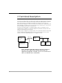
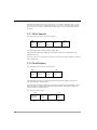
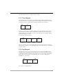
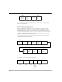
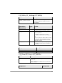
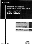
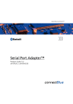
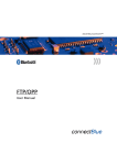
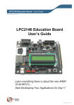
INDUSTRIAL BLUETOOTH™
Bluetooth I2C Bus Adapter™
User Manual 3.0
Bluetooth I2C Bus Adapter™
User Manual 3.0
Copyright © 2003 connectBlue AB
The contents of this document can be changed by connectBlue AB without prior notice and
do not constitute any binding undertakings from connectBlue AB. connectBlue AB is not
responsible under any circumstances for direct, indirect, unexpected damage or consequent
damage that is caused by this document.
All rights reserved.
Release: 0711
Document version: 3.0
Document number: cBProduct-0710-09 (5)
Printed in Sweden.
Trademarks
Registered trademarks from other companies are: Bluetooth is a trademark owned by the
Bluetooth SIG, Inc. Microsoft™, Windows™, Windows NT™, Windows 2000™, Windows
CE™, Windows ME™, Windows XP™ are registered trademarks from Microsoft
Corporation.
Contents
1
INTRODUCTION ..................................................................................... 7
1.1
2
RELATED DOCUMENTS ........................................................................... 7
FUNCTIONAL DESCRIPTION ............................................................. 8
2.1 SERIAL INTERFACE ................................................................................. 9
2.2 IO PINS ................................................................................................... 9
2.3 PROTOCOL OVER AIR .............................................................................. 9
2.3.1 Write Request ................................................................................ 10
2.3.2 Read Request................................................................................. 10
2.3.3 Time Request ................................................................................. 11
2.3.4 Tag Request................................................................................... 11
2.3.5 Combined Requests ....................................................................... 12
2.4 EVENTS ................................................................................................. 13
AT COMMANDS REFERENCE .................................................................. 14
2.5 MISCELLANEOUS COMMANDS ............................................................. 14
2.5.1 Read_I2C_Setttings (AT*AMIS?) ................................................. 14
2.5.2 Write_I2C_Setttings (AT*AMIS=) ................................................ 15
2.5.3 Read_I2C_Events (AT*AMRIE=)................................................. 15
2.5.4 Write_I2C_Event (AT*AMWIE=)................................................. 16
5
6
1 Introduction
This document describes the functionality of the Bluetooth I2C Bus Adapter. The Bluetooth
I2C Bus Adapter is a variant of the standard Serial Port Adapter (SPA) that implements the
master side of the I2C bus interface. It is configured, using AT commands, in exactly the
same way as the standard Serial Port Adapter. The Bluetooth I2C Bus Adapter firmware is
available for the following products:
•
cB-OEMSPA311
•
cB-OEMSPA331
1.1 Related Documents
•
The Serial Port Adapter AT Commands document, contains a description of the
AT commands supported in the standard Serial Port Adapter. It also contains
information on how to use the AT commands to create Bluetooth applications.
The command line format and data types used for the AT commands are defined
in this document.
•
OEM Serial Port Adapter Electrical & Mechanical Datasheet
•
I2C-Bus Specification, version 2.1, January 2000
7
2 Functional Description
The Bluetooth I2C Bus Adapter is a variant of the standard SPA that implements the master
side of the I2C interface. It provides functionality to Bluetooth enable a number of slaves on
an I2C bus. Instead of connecting the I2C master device directly to the I2C bus, the
Bluetooth I2C Bus Adapter is connected. If the previous “master device” supports Bluetooth
and a simple I2C “look-alike” protocol over air, the previous “master device” can access all
I2C slaves available on the I2C bus over Bluetooth.
The Bluetooth I2C Bus Adapter is configured using the same AT commands as for the
standard Serial Port Adapter (see Serial Port Adapter AT Commands document) with some
additions described later in this document.
Typically it is pre-configured once using a toolbox or AT commands, and then mounted and
used for reading and writing data to/from the slaves on the I2C bus. 0f course it is also
possible to use it more dynamically and/or to re-configure it over air.
Device with
Bluetooth
SPP or DUN
Profile
Simple I2C “lookalike” protocol over
air.
Bluetooth
Bluetooth
I2C Bus
Adapter
I2C Bus
I2C
Slave
I2C
Slave
Figure 1 The Bluetooth I2C Bus Adapter is connected to the I2C bus.
The remote device supports either the SPP or DUN profile and
implements the simple I2C “look-alike” protocol over air. The host can
then access all the I2C slaves on the I2C bus.
8
2.1
Serial Interface
The serial port of the Bluetooth I2C Bus Adapter is only used to execute AT commands.
Hence, it is not possible to transmit data transparently over air as with the normal serial port
adapter.
Please note that HW flow control is not supported. The CTS pin is instead used as an
external trig signal.
2.2 IO Pins
The following pins differ from the normal serial port adapter.
•
Serial Select 0: I2C Serial Data (SDA). The SDA pin has a 47kΩ internal pull-up to
VCC (2.9-3.1V). Normally, a 2.2kΩ is more common in I2C applications and a
2.2kΩ external pull-up could be used if necessary.
•
Serial Select 1: I2C clock (SCL). The SCL pin has a 47kΩ internal pull-up to VCC
(2.9-3.1V). Normally, a 2.2kΩ is more common in I2C applications and a 2.2kΩ
external pull-up could be used if necessary.
•
UART-CTS: External trig input.
•
UART-RTS: Not used.
See Electrical and Mechanical data sheet for details.
2.3 Protocol over air
To communicate with the Bluetooth I2C Bus Adapter over air, a simple I2C “look-alike”
protocol must be used.
The following request packets are defined:
•
Write: Writes data to I2C bus.
•
Read: Reads data from I2C bus.
•
Time: Special packet to timestamp response packets.
•
Tag: Special packet to set an identifier to a request packet. The identifier is
included in the response packet. Hence, it is possible to identify what response
that is associated with what request.
Each packet consists of a start byte and a stop byte. The start byte is also used as the
request packet identifier. Hence, there are several actual values of a start byte depending on
what packet type it is. The stop byte can be replaced by the start byte of a new packet. A
combined packet is then created. Typically, for I2C, this means a repeated write or a
repeated read.
There are also two types of response packets defined.
•
ACK: Response to a successfully performed request.
•
NAK: Response to an unsuccessfully performed request.
9
Note that these packets are only received if there is some data to transmit from e.g. a read
request. If the request only contained an I2C write, no response is sent. One way to always
get a response is to create a combined packet with a tag in it. At least the tag will then be
sent back.
2.3.1 Write Request
The write packet executes an I2C write operation.
MSB
LSB
Data
Write:
I2C Slave
Data
0xA1
Address
Length
1 byte
1 byte
Stop:
0xA3
1 byte
1 byte
The data length is specified by the “Data Length” byte.
When the Bluetooth I2C Bus Adapter gets the packet it writes the included data to the
addressed I2C slave.
There is no response to this packet. If a response is needed, the request should be combined
with a tag request.
2.3.2 Read Request
The read packet executes an I2C read operation.
MSB
LSB
Read:
I2C Slave
Data
Stop:
0xA2
Address
Length
0xA3
1 byte
1 byte
1 byte
1 byte
The data length specifies how many bytes the Bluetooth I2C Bus Adapter should expect
when performing the read operation.
When the Bluetooth I2C Bus Adapter gets the packet it reads the specified number of bytes
and sends an ACK or NAK packet back with the included data. Note that the application
must keep track on what the data is.
The response to this request is.
MSB
Data
NAK: 0xA9
Length
1 byte
10
LSB
ACK: 0xA8
1 byte
Data
Stop:
0xA3
1 byte
The “Data Length” byte is the number of bytes in “Data”.
2.3.3 Time Request
The time packet does not execute any I2C operations at all. Instead an ACK/NAK packet is
sent back with the time read by the Bluetooth I2C Bus Adapter. Normally, this is only useful
if the packet is part of a combined packet with I2C read and/or write operations.
MSB
LSB
Time:
Stop:
0xA4
0xA3
1 byte
1 byte
To measure time, the Bluetooth I2C Bus Adapter must continuously keep a timer running.
This affects the stop mode and may not be desirable. Therefore, the time tracking is by
default disabled. If a time request is sent to the module when the time tracking is disabled,
it will return four bytes set to zero.
The response to the time request is.
MSB
LSB
Time
ACK: 0xA8
Data
NAK: 0xA9
Length
1 byte
1 byte
Stop:
0xA3
4 bytes
1 byte
The time is represented as four bytes (Big Endian) and the measured time is the number of
milliseconds since power on. The “Data Length” byte is 4 for a time response. The timer will
reset after 1 week.
2.3.4 Tag Request
The tag packet does not execute any I2C operations at all. Instead an ACK/NAK packet is
sent back with the included tag value. Normally, this is only useful if the packet is part of a
combined packet with I2C read and/or write operations. It provides a way to identify what
request that a received response is associated with. Also, it is a way to always get an
ACK/NAK for a write request.
MSB
Tag:
LSB
Tag Value
0xA5
1 byte
Stop:
0xA3
1 byte
1 byte
The response to the tag request is.
11
MSB
LSB
ACK: 0xA8
Data
NAK: 0xA9
Length
Tag Value
0xA3
1 byte
1 byte
Stop:
1 byte
1 byte
The returned tag value has the same value as the tag in the request. The “Data Length”
byte is 1 for a tag response.
2.3.5 Combined Requests
Instead of transmitting a separate e.g. write or read request it is possible to combine
different packets into one packet over air. The Bluetooth I2C Bus Adapter will perform
repeated read and write operations on the I2C bus for a combined read/write request.
To create combined requests the stop byte of the previous packet is left out and instead the
start byte of the next packet acts as both the stop byte and start byte. It is only the last
request in a combined request that has a stop byte.
For example, assume that a combined request with a tag, I2C write, I2C read, and time
request shall be created. It then looks like.
MSB
Tag Value
Tag:
0xA5
1 byte
1 byte
Data
Write:
I2C Slave
Data
0xA1
Address
Length
1 byte
1 byte
1 byte
LSB
Read:
I2C Slave
Data
Time:
Stop:
0xA2
Address
Length
0xA4
0xA3
1 byte
1 byte
1 byte
1 byte
1 byte
The response to the above combined packet will be.
MSB
LSB
ACK: 0xA8
Data
Tag
Read
NAK: 0xA9
Length
Value
Data
1 byte
1 byte
1 byte
”Data
Length”
from read
packet
12
Time
Stop:
0xA3
4 bytes
1 byte
The response “Data Length” is the added number of bytes of the tag value, read data and
the time.
Please note that the device that made the request must keep track on what the response
must look like.
2.4 Events
It is possible to store request packets, in the Bluetooth I2C Bus Adapter, associated with
specific events. A request is then executed when its associated event occurs.
Possible events are:
•
Power on
•
Bluetooth connection is setup
•
Bluetooth connection is terminated
•
Periodic – only executed if there is an active Bluetooth connection or if the
Bluetooth I2C Bus Adapter is configured for I2C interface always enabled.
•
External Trig (CTS pin) – only executed if there is an active Bluetooth connection
or if the Bluetooth I2C Bus Adapter is configured for I2C interface always enabled.
•
Best Effort – continuously executed if there is no other events or data available.
Hence, the event will execute as fast as possible with the shortest possible time in
between as long as there are no other events or incoming I2C data over air.
When an event is triggered e.g. a Bluetooth connection is setup, the associated request is
executed. The request is a number of bytes that complies to the protocol over air (see
Section 2.3.
For example, assume that a Bluetooth I2C Bus Adapter is connected to a sensor on an I2C
bus. One configuration could then be:
1.
Power on event: The request writes to the control register of the sensor to initialize the
sensor.
2.
Bluetooth connection is setup: The request writes to the control register of the sensor
to make the sensor leave sleep mode and enter online mode.
3.
Bluetooth connection is terminated: The request writes to the control register of the
sensor to make the sensor leave online mode and enter sleep mode.
4.
Periodic: The request, that is periodically being executed, reads the sensor value, which
is then sent back to the remote device currently connected.
Hence, by using the I2C events it is possible to pre-configure the Bluetooth I2C Bus Adapter
to completely control an I2C slave without the need for the host device to send a lot of
requests.
13
AT Commands Reference
This section describes only the differences in AT commands compared to the standard serial
port adapter.
2.5 Miscellaneous Commands
2.5.1 Read_I2C_Setttings (AT*AMIS?)
AT Command
Description
AT*AMIS?<CR>
This command reads the I2C settings.
Responses
Description
<CR><LF>*AMIS:<bit_rate>,<enable_time>,
<disable_on_disconnect><CR><LF>OK<CR><LF>
Successful response.
<CR><LF>ERROR<CR><LF>
Error response.
Response
Parameters
Type
Value
bit_rate
Enumerator
1: Bit rate on I2C bus of 100 kbits/s
2: Bit rate on I2C bus of 400 kbits/s (default)
enable_time
Enumerator
Enables the Bluetooth I2C Bus Adapter to track
time since power on.
0: Disabled – Returns time = 0 (default)
1: Enabled – Returns milliseconds since power
on.
Please note that when enabled a timer is running
in the module. This means that the module will
never enter stop mode when there is an active
Bluetooth connection.
disable_on_disconnect
14
Enumerator
0: Always let the I2C interface be enabled (default)
1: Disable I2C interface if there is no Bluetooth
connection.
2.5.2 Write_I2C_Setttings (AT*AMIS=)
AT Command
Description
AT*AMIS=<bit_rate>, <enable_time>,
<disable_on_disconnect><CR>
Writes the I2C bus interface configuration.
Note that the configuration is always stored in the
startup database.
Command
Parameters
Type
Value
bit_rate
Enumerator
1: Bit rate on I2C bus of 100 kbits/s
2: Bit rate on I2C bus of 400 kbits/s (default)
enable_time
Enumerator
Enables the Bluetooth I2C Bus Adapter to track
time since power on.
0: Disabled -> Returns time of 0 (default)
1: Enabled -> Returns milliseconds since power
on.
Please note that when enabled a timer is running
in the module. This means that the module will
never enter stop mode when there is an active
Bluetooth connection.
disable_on_disconnect
Enumerator
0: The I2C bus is always enabled (default)
1: Disable I2C interface if there is no Bluetooth
connection.
Responses
Description
<CR><LF>OK<CR><LF>
Successful response.
<CR><LF>ERROR<CR><LF>
Error response.
2.5.3 Read_I2C_Events (AT*AMRIE=)
AT Command
Description
AT*AMRIE=<event><CR>
This command reads a pre-configured I2C request associated
with an event.
If a pre-configured event is triggered, the associated I2C request is executed.
Responses
Description
15
<CR><LF>*AMRIE: <period>, <i2c_request_length>,
<i2c_request><CR><LF>OK<CR><LF>
Successful response.
<CR><LF>ERROR<CR><LF>
Error response.
Response
Parameters
Type
Value
event
Enumerator
1: Power On
2: Bluetooth connection up
3: Bluetooth connection down
4: Timer (periodic)
5: External Trig (CTS pin activated)
6: Best effort (continuously executed as quickly
as possible if no other I2C commands are available)
Note that the Timer and External Trig events are
only executed if there is an active Bluetooth
connection or if the Bluetooth I2C Bus Adapter is
configured for I2C interface always enabled.
period
Enumerator
The Timer event is periodically executed (if configured) with this period in milliseconds.
I2c_request_length
Enumerator
Number of bytes of the I2C request.
I2c_request
Enumerator
I2C request where the byte code must apply to
the protocol specified in Section 2.3.
Please note that the <i2c_request> of the read
command (AT*AMRIE) is not coded. This will
change in future versions of the I2C adapter. See
<i2c_request> of the write command
(AT*AMWIE).
2.5.4 Write_I2C_Event (AT*AMWIE=)
AT Command
Description
AT*AMWIE=<event>, <period>,
<i2c_request_length>,
<i2c_request><CR>
This command configures an I2C request.
If a pre-configured event is triggered, the associated
I2C request is executed.
Note that the configuration is always stored in the
startup database.
Response
Parameters
16
Type
Value
event
Enumerator
1: Power On
2: Bluetooth connection up
3: Bluetooth connection down
4: Timer (periodic)
5: External Trig (CTS pin activated)
6: Best effort (continuously executed as quickly
as possible if no other I2C commands are available)
Note that the Timer and External Trig events are
only executed if there is an active Bluetooth
connection or if the Bluetooth I2C Bus Adapter is
configured for I2C interface always enabled.
period
Enumerator
The Timer event is periodically executed (if configured) with this period in milliseconds.
I2c_request_length
Enumerator
Number of bytes of the I2C request.
I2c_request
Enumerator
I2C request where the byte code must apply to
the protocol specified in Section 2.3.
Since the I2C request is a byte stream, which
may contain control characters part of the AT
command, some bytes need to be coded.
Symbol
\
BS
LF
CR
,
Hex
0x5C
0x08
0x0A
0x0D
0x2C
Coded (3 bytes)
0x5C 0x35 0x43 (“\5C”)
0x5C 0x30 0x38 (“\08”)
0x5C 0x30 0x41 (“\0A”)
0x5C 0x30 0x44 (“\0D”)
0x5C 0x32 0x43 (“\2C”)
For example:
“0xA1 0x08 0x01 0x15 0xA3” must be coded to
“0xA1 0x5C 0x30 0x38 0x01 0x15 0xA3”
Please note that the <i2c_request> of the read
command (AT*AMRIE) is not coded. This will
change in future versions of the I2C adapter.
Responses
Description
<CR><LF>OK<CR><LF>
Successful response.
<CR><LF>ERROR<CR><LF>
Error response.
17