1
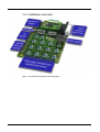
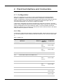
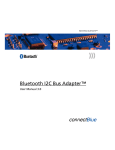
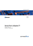
INDUSTRIAL BLUETOOTH™
Bluetooth IO Development Board
cB-0911
User Guide
Bluetooth IO Development Board
cB-0911
User Guide
Copyright © 2006 connectBlue AB.
The contents of this document can be changed by connectBlue AB without prior
notice and do not constitute any binding undertakings from connectBlue AB.
connectBlue AB is not responsible under any circumstances for direct, indirect,
unexpected damage or consequent damage that is caused by this document.
All rights reserved.
Release: 2006-12
Document version: 1.0
Document number: cBProduct-0611-03
Trademarks
Registered trademarks from other companies are: Bluetooth is a trademark owned
by the Bluetooth SIG, Inc., Microsoft™, Windows™, Windows NT™,
Windows 2000™, Windows CE™, Windows ME™, are registered trademarks from
Microsoft Corporation.
Contents
1 Introduction
1.1
1.2
1.3
1.4
1.5
5
Bluetooth IO Development Kit............................................................5
Related Documents ...........................................................................5
Quick start ..........................................................................................5
Hardware overview ............................................................................6
Block Diagram....................................................................................7
2 Electrical Interface and Connectors
2.1
2.2
2.3
2.4
2.5
2.6
8
Configuration......................................................................................8
I/Os.....................................................................................................8
Serial Port Adapter Functionality .......................................................9
Serial Port ..........................................................................................9
Bluetooth IO Module ..........................................................................9
Power Supply .....................................................................................9
Version 1.0 - 2006-12
4
1 Introduction
This documents describes the user functionality of the Bluetooth IO Development Board,
which is used to verify applications based on the Bluetooth IO Module. See Related
Documents below for more info about the functionality of the Bluetooth IO.
The Bluetooth IO Development Board is equipped with LEDs, switches and pin-lists for each
IO. It is also possible to connect external LEDs and switches to some of the IOs (see section
2.2 for more info).
1.1 Bluetooth IO Development Kit
The Bluetooth IO Development Kit contains:
-
Two Bluetooth IO Development Boards
-
Two Bluetooth IO Modules mounted on the Development Boards.
-
One serial null modem cable
Used for configuring the modules.
-
Two USB power supply cables
Used to power supply the boards from a USB port.
-
One CD
Containing manuals, firmware and software tools.
1.2 Related Documents
-
The Bluetooth IO Module Functional Description and AT Commands Specification
describes the functionality of the Bluetooth IO Module. The Bluetooth IO functionality is
implemented using a simple protocol on top of the Bluetooth Serial Port Profile (SPP).
Much of the functionality remains the same as for the standard SPA but additionally to
this it is possible to use some of the connectors as inputs or outputs.
-
The Serial Port Adapter AT Commands document contains a description of the AT
commands supported in the Serial Port Adapter. It also contains information on how to
use the AT commands to create Bluetooth applications.
-
The OEM Serial Port Adapter Electrical & Mechanical Datasheet contains important
information about Bluetooth OI hardware. The hardware is the same as the OEM Serial
Port Adapter. Read this document if you are interested in the mechanical and electrical
specification of the Bluetooth IO.
1.3 Quick start
The boards are factory configured with one board as a client and one as a server. The client
is configured to connect to the server, the client module can be detected by power-on only
one device at a time and the client module should turn the Status LED (see section 2.3) blue
for 5 seconds.
The client board is also factory configured with the 6 first IOs as outputs and the 6 last IOs
as inputs and the reverse configuration on the server board (see Table 1).
To test the functionality on the Development Board follow the simple steps below:
1. Connect the power cable to the Development Board.
2. Press on the buttons SW1 - SW6 (IO-0, IO-1, IO-4, IO-6, IO-8, IO-9) on the server
board, which is configured as input on the server board. The LEDs on client will light
according the button presses.
3. Test the inputs on the client board SW9-SW14 (IO-10 – IO-15) in the same way.
Version 1.0 - 2006-12
5
1.4 Hardware overview
Figure 1 - The Bluetooth IO Development Board disposition.
Version 1.0 - 2006-12
6
1.5 Block Diagram
Figure 2 - Block diagram of the Bluetooth IO Development Board. Notice that this is only a symbolic
diagram and all components are not included.
Version 1.0 - 2006-12
7
2 Electrical Interface and Connectors
2.1 Configuration
Each IO is configured to be an input or output. The Bluetooth IO Development Board
hardware configuration needs to match the software configuration of the Bluetooth IO
module. The Bluetooth IO Development Board is configured with the DIP switches SW7 and
SW8 (see Table 1) and see the “Bluetooth IO Module Functional Description and AT
Commands Specification” for info how to configure the module.
In the factory configuration one board is configured as a client one as a server. The client
board is factory configured with the 6 first IOs as outputs and the 6 last IOs as inputs and the
reverse configuration on the server board (see Table 1). The client module can also be
detected by powering only one device at a time and the client module should turn the Status
LED (see section 2.3) blue for 5 seconds.
2.2 IOs
The Bluetooth IO Development Board is equipped with LEDs, switches and pin-lists for each
IO. It is also possible to connect external LEDs and switches to some of the IOs (see Table
1).
Table 1: Signals on J2
Signal
Configuration
DIP switch
LED
Switch
Signal pin External
number J6 LED/SW pin
number J7
Factory
configuration
IO-0
SW8-6
LD1
SW1
1
LED: 9
SW: 1
Conf: 10
Client: Output
Server: Intput
IO-1
SW8-5
LD2
SW2
2
LED: 11
SW: 3
Conf: 12
Client: Output
Server: Intput
IO-2
Used for Green LED / Restore Default Settings and not available as IO*
IO-3
Used for Blue LED and not available as IO*
IO-4
IO-5
IO-6
IO-7
SW8-4
LD3
SW3
5
LED: 13
SW: 5
Conf: 14
Client: Output
Server: Intput
7
LED: 15
SW: 7
Conf: 16
Client: Output
Server: Intput
Used for UART-TxD and not available as IO*
SW8-3
LD4
SW4
Used for UART-RxD and not available as IO*
IO-8
SW8-2
LD5
SW5
9
-
Client: Output
Server: Intput
IO-9
SW8-1
LD6
SW6
10
-
Client: Output
Server: Intput
Version 1.0 - 2006-12
8
Signal
Configuration
DIP switch
LED
Switch
Signal pin External
number J6 LED/SW pin
number J7
Factory
configuration
IO-10
SW7-6
LD7
SW9
11
-
Client: Input
Server: Output
IO-11
SW7-5
LD8
SW10
12
-
Client: Input
Server: Output
IO-12
SW7-4
LD9
SW11
13
-
Client: Input
Server: Output
IO-13
SW7-3
LD10
SW12
14
-
Client: Input
Server: Output
IO-14
SW7-2
LD11
SW13
15
-
Client: Input
Server: Output
IO-15
SW7-1
LD12
SW14
16
-
Client: Input
Server: Output
RESET
-
-
SW15
17
-
VCC_3V3
-
-
-
20
2, 4, 6, 8, 20
GND
-
-
-
19
19
* Possible to use as IO with alternative mounting, please contact connectBlue for more info
2.3 Serial Port Adapter Functionality
The Bluetooth IO modules are based on the connectBlue OEM Serial Port Adapter (cBOEMSPA) products and the IO functionality is added on top of the cB-OEMSPA (see the
Serial Port Adapter AT Commands document). The serial settings can be restored to factory
settings (57600bits/s, 8 data bits, 1 stop bit, no parity) with the Restore switch (SW16) and
the status is indicted with Status RGB LED (the red LED is not used).
2.4 Serial Port
The serial port of the Bluetooth IO module is accessible via a D-Sub9 male connector on the
Development Board to be able to configure the module and upgrade the firmware. Only the
data signals (RxD and TxD) are available. The flow control and modem signals are crossed
on the Development Board (see Figure 2).
2.5 Bluetooth IO Module
The Bluetooth IO module should be mounted with two M2 screws on the J5 connector. See
Figure 1 for the orientation of the module.
2.6 Power Supply
The development board can be supplied with the delivered USB to 2.1mm power jack cable.
The USB connector should be connected to a USB port that can deliver 100mA. The
Development Board requires 5.0±0.5 VDC, 100mA power supply.
Version 1.0 - 2006-12
9