1
1331 USER MANUAL AND PROGRAMMING INSTRUCTIONS - UM1331/E/3-3-2005
- 16 -
Bottom Left we see the N Store and its decoders, IC's 20 (store) and IC's 1, 2
and 3. The N Store is clocked by W4 and its output is enabled by AFGO, a version
of Dataway BUSY. The N value from the store is fed to the decoders and also OUT
onto the ACB EN lines while it is doing a CAMAC cycle. At all other times it
accepts EN data from the ACB and feeds it to its decoders. Thus, if it is Master
(Stations 24 and 25) then the 1331 will decode any valid ACB EN given to it.
When it is not Master, the decoders are disabled anyway.
Just to the right of the N Store we see the Subaddress Store/Counter. This is
normally simply loaded with the desired subaddress value which is output onto
the Dataway as usual. If, however, the Software LAM is set (remember that it
should be Masked OFF to avoid an Interrupt), then the Count Enable pin of the
chip, pin 7, will be high allowing the End Pulse from the CAMAC cycle generator
to increment the subaddress, provided, of course, that Switch 1D is open to
enable IC43 pins 4,5,6. This is intended for applications where a lot of
subaddresses need to be scanned in turn, for example a 16 channel ADC, to save
having to reload the subaddress each time.
Top Right we see the Function Code latch, IC22, and its decoding PROM, IC26 "IBM
V2". After the new F Code has been latched in, a 100nS pulse delayed by 100nS
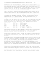
strobes the PROM via pin 15. The outputs of the PROM function as follows:
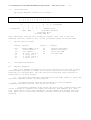
Function Code
0-7
16-23
40-41
48-49
32-37
0-31, 34-37
Action
pulse pin
pulse pin
pulse pin
pulse pin
pulse pin
pulse pin
2
1
6
4
7
5
Result
generate READS2
generate WRITE
set or clear INTEN
set or clear SLAM
set/clear I, generate C/Z
set START FF = CAMAC cycle
Notice how the flip-flops for READS2, WRITE, C and Z, set by the various pulses
from the PROM are all knocked down by End Pulse from the CAMAC cycle generator.
Note also that if either the C or the Z flip-flop is set, then NOBUSY is
generated, IC45 pins 13,12,11, to inhibit all the A,F and N outputs.
At the bottom of this section of the circuit, on the right, we see the Q and X
latches, which sample these lines at S1 time. The outputs of these latches go to
the SR buffer (Status Register), IC24, whose outputs are enabled onto the Data
Bus by R3.
Bottom Right we see the CAMAC cycle generator, set in motion as described above
by the START signal, and clocked by the 10MHz master oscillator, IC40, RV1. The
operation of this state machine is beyond the scope of this manual, but suffice
it to say that it conforms to all the specifications of EUR6500, including
aborting on ACL etc. and can operate in either R/G or ACL modes.
The monostable IC46 and flip-flop IC47 act to ensure that End Pulse is only
generated on the trailing edge of a complete BUSY pulse, and therefore that ACL
aborted cycles are ignored from the point of view in particular of resetting the
START latch.
Also in this corner of the circuit is the power-on-reset system which generates
active low and active high reset pulses for all parts of the circuit for about
200mSec after power-on and also in response to the front panel reset button and
the reset line from the computer.
The rather complicated system of zener and transistor etc. ensures that even a
brief interruption of the supply will be recognised and mal-operation avoided.