1
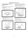
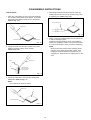
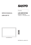
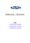
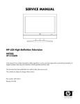
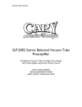
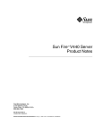
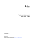
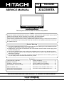
DISASSEMBLY INSTRUCTIONS
3. When IC starts moving back and forth easily after
desoldering completely, pickup the corner of the IC using
tweezers and remove the IC by moving with the IC
desoldering machine. (Refer to Fig. 1-3.)
1. REMOVAL AND INSTALLATION OF
FLAT PACKAGE IC
REMOVAL
NOTE
1. Put Masking Tape (cotton tape) around the Flat Package
IC to protect other parts from any damage.
(Refer to Fig. 1-1.)
Some ICs on the PCB are affixed with glue, so be
careful not to break or damage the foil of each IC
leads or solder lands under the IC when removing it.
NOTE
Masking is carried out on all the parts located within
10 mm distance from IC leads.
Masking Tape
(Cotton Tape)
Blower type IC
desoldering
machine
IC
Tweezers
Fig. 1-1
IC
Fig. 1-3
2. Heat the IC leads using a blower type IC desoldering
machine. (Refer to Fig. 1-2.)
4. Peel off the Masking Tape.
NOTE
5. Absorb the solder left on the pattern using the Braided
Shield Wire. (Refer to Fig. 1-4.)
Do not rotate or move the IC back and forth , until IC
can move back and forth easily after desoldering the
leads completely.
NOTE
Do not move the Braided Shield Wire in the vertical
direction towards the IC pattern.
Blower type IC
desoldering machine
Braided Shield Wire
Soldering Iron
IC
IC pattern
Fig. 1-2
11
Fig. 1-4