1
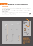
1
Congratulations on your purchase.
The Twenty10 model has been designed and tested to the European standard for
city bikes: EN14764: 2005
(a)
Foreword
The intended usage of this product is for personal transportation within an
urban environment. Strong merits are derived from what has been
excluded from the simple design: i.e. suspension or multiple gears.
The bike is tested inline with the EU standard for city bikes. Whilst it is
entitled to be called a BMX bike, people who purchase the bike must
acknowledge that competitive or extreme riding is not covered by the
warranty because stresses on the bike can exceed the test conditions. The
original components were selected on acceptable compromises between
value for money, strength, weight and corrosion resistance, so the bike
offers many years of efficient service if ridden sensibly and maintained
according the this instruction manual.
Enjoy your bike at every opportunity.
2
Contents
Page
a
Type of use for which the bicycle has been designed
2
b
Preparation for riding
4
c
Minimum saddle height
4
d
Suspension system adjustment
4
e
Recommendations for safe riding
4
f
Permissible total weight
5
g
National legal requirements on public roads
5
h
Recommended tightening of fasteners
5
i
Quick-release devices
5
j
Self Assembly of the bike
6
k
Lubrication
8
l
Correct chain tension
8
m
Adjustments of gears
8
n
Adjustment of brakes
9
o
General maintenance
10
p
Replacement parts for safety-critical components
10
q
Care of the wheel-rims
10
r
Appropriate spares
10
s
Accessories
11
t
A note on child seats and incompatible saddles
11
u
An advisory note for your safety
11
3
(b) Preparation for riding:
Saddle Height Adjustment: Ensure that the both feet can touch the ground
whilst seated upon the saddle. There is a ‘minimum insertion’ mark on the
seat post that should not be exposed above the frame. So long as this
marking is tightened fully within the seat tube the bicycle is being operated
within the tested range.
Brake Configuration: The bike should be set-up with the right brake lever
operating the front brake and the left brake lever operating the rear brake.
Ensure that you are familiar with the configuration. It is customary for
continental bikes to have the brake controls in the opposite configuration. If
the opposite configuration is more familiar or instinctive to you [the rider] then
it could be advantageous to unhook the caliper arms and swap the cables to
the opposite levers (through the slots in the barrel adjusters – see part ‘n’).
(c) Minimum saddle height: Ensure that you can pedal safely through a
complete rotation of the pedals.
(d) Suspension Adjustment: No suspension components are fitted to the
bicycle to minimise maintenance and weight and for optimal energy
efficiency within an urban environment.
(e) Recommendations for safe riding: Always use a bicycle helmet,
Ensure that regular checks on brake cable adjustment and brake block wear
are carried out by a qualified bicycle technician. Be aware of possible
increased braking distances in wet weather and periodically apply the brakes
to clear water from the rim braking surfaces. Be sure that the tyres are
correctly inflated and that they have sufficient remaining tread. Avoid ice
patches when riding in winter. Always use lights at night. Never approach a
road junction on the inside of lorries or busses where they may be turning
across your path – they may not see you. Always ride well clear of parked
cars where doors may be opened into your path. Be alert; keep your eyes
out for any potential dangers throughout every ride.
4
f) Permissible total weight: The maximum combined weight of the bicycle,
rider and luggage should not exceed 100kg mass or 1000N. Mass of rider
and luggage being equal to this figure with the bike’s mass subtracted.
g) Requirements for the public Highway: Ensure that the bicycle complies
with BS6102 at the point of purchase. The bicycle must have front and rear
reflectors, a bell and a chain guard. Tyres should have sound remaining
tread and wheels should also have reflectors. Both front and rear brakes
should function independently. It is the responsibility of the rider to ensure
that they do not compromise their own safety or the safety of other road
users around them.
h) Recommended tightening of fasteners:
Handlebar binder on stem: 17Nm
Handlebar stem onto fork steerer tube: 12Nm
Saddle to seat post (lateral bolt): 14Nm
Seat-pillar binder: 5Nm
Front wheel spindle Nuts: 20Nm
Rear wheel spindle Nuts: 30Nm
i) No Quick-Release clamps are used on the bike as an anti-theft
precaution. This increases security when locked up in public places.
5
j) The Big BMX is normally supplied fully assembled by the retailer. In
cases where the bike has arrived with the end user in an incomplete state of
assembly, always ensure that an experienced and qualified bicycle
technician completes the assembly process. Failure to comply with this
recommendation may invalidate the warranty of the product.
The following steps are required to fully assemble the bicycle as it is
removed from the original packaging:
i)
Create a clean and tidy work space in which to assemble the bike. You will
require a simple toolkit with a narrow adjustable wrench and 5 & 6mm Allen
keys. Use the shipping carton as a bin for the inner packaging.
ii)
Carefully open the cardboard shipping carton and lift out the Saddle assembly
and the other small box which contains the pedals and reflectors. Lift out the
bicycle together with the wheels which may be attached with tie-wraps and tape
as shown in photo 1:
6
Carefully separate each part and dispose of all packaging. Arrange the components as
shown in Photo 2 to ensure that all necessary contents are present. Note: Take special
care not to stretch or kink the outer cable of the rear brake which is pre-attached to the
handlebar and the frame.
iii)
Attach the handlebars to the stem by removing the handle bar binder plate from
the front of the stem and re-fitting with the handlebars in place. Ensure that the
handlebar is centrally located within the clamp and at a similar vertical angle to
the fork blades whilst tightening the four bolts:
iv)
Insert the seat post into the frame beyond the minimum insertion mark and
tighten the clamp. Also ensure that the saddle clamp at the top of the seat tube is
fully tightened with the saddle angled to the rider’s preferred orientation. For
reasons of comfort, some people prefer the rear end of the saddle to be slightly
lower than the front. The new owner of this bike may find a preferred position
through trial and error.
v)
Insert the front wheel. Ensure that the hook washers engage with the holes in the
fork dropouts. Tighten the wheel nuts whilst ensuring that the wheel rim is
centrally located at the top of the fork blades. Sometimes the wheel rim can
move off centre whilst tightening the wheel nuts so be prepared to loosen the
nuts and retighten several times over to achieve a central position. A well centred
rim is vital when setting up the front brakes.
vi)
Thread the front brake cable into the respective V-brake caliper arm and follow
the instructions for brake adjustment under part (n) within this owner’s manual.
vii)
Tighten the pedals into the cranks. Note that there are left and right handed
pedals because the left hand pedal has a reversed thread.
viii)
Finally, fit the chain guard, bell and reflectors and adjust the tyre pressures.
Check that the handlebars are aligned to the wheel, use a spoke key to true the
rims and follow the instructions under parts (o), (n), (b), (c), (h) and (q) in this
user manual to ensure that the bike is safe, reliable and comfortable to ride.
7
k) Lubrication – Regularly lubricate the chain with a suitable product. Do not
attempt to lubricate the brake components as this may contaminate the
reaction surfaces. Periodically take the bike to a qualified bicycle technician
to have the bottom bracket, headset, hubs and brake components suitably
greased.
l) Correct chain tension is achieved by loosening the rear axle nuts and
adjusting the longitudinal axle adjusters within the dropouts. Re-tighten the
axle nuts whilst holding the wheel centrally between the chain stays and
rotate the cranks through a complete rotation. If during the rotation the chain
becomes tight or excessively loose, repeat the adjustment procedure as
above. Assessment of chain tension should be done by measuring the
maximum vertical deflection at the midpoint of the chain (half way between
the front chain-ring and the rear sprocket). No more than 40mm of vertical
movement should be attainable at this midpoint within a full crank rotation.
m) No gear system is fitted to the bike, in order to reduce weight,
maintenance and initial purchase cost.
8
n) Adjustment of brakes: The brake levers have barrel adjusters threaded
into the lever assembly. For both front and rear brakes, ensure that the cable
is adjusted to a position within the v-brake caliper that enables the
aforementioned barrel adjuster to prevent the brake lever from touching the
handlebar grips when the brake is fully applied. Seven recommended steps
for initial set-up are as follows:
1: Loosen off the cable clamp on the V-Brake caliper arm.
2: Unscrew the lever assembly’s barrel adjuster so that 50% of the full travel
is available in or out of the brake lever assembly.
3: Align each brake block correctly to the wheel rim surface and tighten.
4: Hold the brake blocks tightly against the rim surfaces and pull the cable
through the cable clamp.
5: Tighten the cable clamp in this position with the cable fully pulled through
as described in step 4, above.
6: Screw the barrel adjuster into the lever assembly to release the brake
blocks from the wheel. Approximately 50% of lever travel should fully apply
the brake (set the barrel adjuster accordingly).
7: Ensure that both of the v-brake caliper arms move away from the wheel
rim simultaneously and by an equal distance when the brake lever is
released. This can be achieved by adjusting the spring tension screws that
are located near the pivots.
handlebar grip
handlebar
lever travel
cable clamp
brake lever
tyre
wheel
rim
adjuster
V-brake
calliper
arm
pivot
brake
block
barrel
cable
spring
tension
adjustment
screw
9
V-Brake
System
o) General maintenance: Ensure that an experienced bicycle mechanic
regularly checks over the bicycle with safety in mind. Ensure that both front
and rear brakes function correctly and that cables are not frayed of loose.
Ensure that the brake blocks are not worn below the minimum. Ensure that
each nut and bolt throughout the bicycle is sufficiently tight to facilitate sound
function. Ensure that the tyres have good remaining tread and that they are
inflated to the correct pressures. Ensure that reflectors are kept clean.
Ensure that the bell functions. Ensure that each component with a
mechanical movement is regularly greased or lubricated for a long life span.
Ensure that the chain is sufficiently tensioned and lubricated
p) Only use genuine replacement parts for safety-critical components. A
qualified Bicycle technician can advise on the correct choice of replacement
parts.
q) The rims of the bicycle should be kept straight and true by a qualified
bicycle technician. Periodically check that the wheels have not become
buckled by testing for a free rotation through a complete revolution. If at any
point during the rotation the wheel rim makes contact with a brake block,
either have the wheel straightened by a professional technician or replace
with a new 26” wheel as appropriate. Note: If the bike is ridden with an
excessively worn brake block, the metal substructure of the worn out brake
block can score the rim surface causing dangerous weakening of the wheel.
In this case, do not ride the bike until a replacement wheel has been fitted
and the brakes correctly adjusted to the new rim.
r) Appropriate spares. For general city riding no specific spare parts are
recommended. In the event of a puncture or component failure, walk the bike
to the nearest convenient repair shop, secure locking point, or public
transport facility. Call a taxi, walk or use public transport to complete your
journey. If left locked up in a non-functioning state, be sure to collect the bike
by car when a repair shop is open and take the bike to them. Do not leave
the bike locked up in areas where thieves may consider defeating your
security device.
10
s) Accessories – Minimal accessories are fitted to the bike as original
equipment. See general maintenance in clause (o) above.
t) Do not disregard the importance of suitably covering any coil springs under
your chosen saddle if a child-seat is fitted - to prevent painful trapping of the
child’s fingers.
u) Advisory note - to draw the attention of the rider to possible damage due
to intensive use and to recommend periodic inspections of the frame and
fork:
WARNING: As with all mechanical components, the bicycle is
subjected to wear and high stresses. Different materials and
components may react to wear or stress fatigue in different
ways. If the design life of a component has been exceeded, it
may suddenly fail possibly causing injuries to the rider. Any
form of crack, scratches or change of colouring in highly
stressed areas indicate that the life of the component has been
reached and it should be replaced.
11
290310
12