1
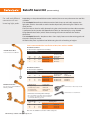
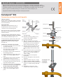
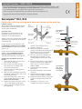
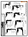
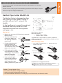
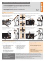
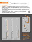
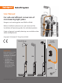
Retrofit System
User Manual
For safe and efficient conversion of
non-lowering light poles.
Range to suit existing pole sizes DN32 to DN80.
Before installation please ensure you have read the
Installation & Operation guides for individual products.
Copies of general assembly drawings are available online
www.swivelpole.com
Copyright © Swivelpole™ Group Pty Ltd 2013
Retrofit Range
Retrofit
Assist Kit
Applications
Allows replacement of faulty
luminaires, upgrades to
new lighting technology and
replacement of corroded or
oversized pole tops.
• Swivelpole™ R11
Conversions reusing
existing pole
• Swivelpole™ R12, R13
Conversion renewing
pole top while utilising
existing pole base
SP-IEC-Retrofit System User Manual-20140724
R11
R12
R13
Retrofit Assist Kit (Patent Pending)
For safe and efficient
conversion of nonlowering light poles.
Depending on the preferred disconnection method, there are two pole conversion tool kits
available.
The Swivelpole™ Retrofit Assist Pole Conversion Tool clamps to and safely supports the
light pole, which is then cold cut with a Ratchet Pipe Cutter, eliminating the need for hot
work permits.
The luminaire can then be safely lowered using the swivel mechanism where disconnection
is performed at the junction box (Retrofit Assist Kit 1) or alternatively by using the Mid
Hinge (Retrofit Assist Kit 2) which allows lowering the luminaire without the need to
disconnect.
The Swivelpole™ Retrofit – R11, R12 or R13 - then simply fastens onto the existing pole and
the pole is ready for service.
All work takes place at platform level eliminating the risks of working at heights.
Tools recommended for installation of R11, R12 and R13 models
Retrofit Assist Kit 1*
For disconnection at junction box or T-fitting
Retrofit Assist Kit 1
Pole Conversion Tool RA-PCT
Ordering Information
To suit Pole Size
Retrofit Assist Kit 1
Includes Pole
Conversion Tool
NPS
DN
OD
Ordering Code
Product Code
11/4”
32
42.4
RAK1-PCT-32
RA-PCT-32
11/2”
40
48.3
RAK1-PCT-40
RA-PCT-40
2”
50
60.3
RAK1-PCT-50
RA-PCT-50
Retrofit Assist Kit 2*
For disconnection at luminaire
Ordering Information
To suit Pole Size
Retrofit Assist Kit 2
Pole Conversion Tool RA-MH-PCT
Mid Hinge RA-MH
Retrofit Assist Kit 2
Includes Pole
Conversion Tool
Includes Mid
Hinge
NPS
DN
OD
Ordering Code
Product Code
Product Code
11/4”
32
42.4
RAK2-PCT-32
RA-MH-PCT-32
RA-MH-32
11/2”
40
48.3
RAK2-PCT-40
RA-MH-PCT-40
RA-MH-40
2”
50
60.3
RAK2-PCT-50
RA-MH-PCT-50
RA-MH-50
* All Kits include
Product Code
1 x Riggers Bag
RA-RGB-01
1 x Ratchet Pipe Cutter
RA-RPC-01
3 x Spare blades
RA-RPC-01-SB
1 x Socket wrench
RA-SKWR
Retrofit Assist - Ratchet Pipe Cutter
Retrofit Assist - Socket Wrench
Retrofit Assist - Interchangeable Pole Clamps
Kits come with the pole clamp sizes as indicated in
the ordering code. Other sizes can be ordered to
accommodate different pipe sizes.
Ordering Information
To suit Pole Size
Ordering Code
Pole Conversion Tool
Mid Hinge
42.4
RA-IPC-32
MH-IPC-32
40
48.3
RA-IPC-40
MH-IPC-40
50
60.3
RA-IPC-50
MH-IPC-50
NPS
DN
OD
11/4”
32
11/2”
2”
Note: Tools are available for conversion of PVC coated poles.
CAD drawings available online: swivelpole.com
Retrofit System - USER GUIDE
Before installation please ensure you have read Swivelpole™ Installation & Operation Guide –
Importance of Safe Swivel™ joint orientation and Operation and safety information. This guide
should be followed to ensure the Swivelpole™ is assembled and installed safely and correctly.
Copies of general assembly drawings are available online www.swivelpole.com
Copyright and Patent Pending Swivelpole™ Group Pty Ltd 2013
Swivelpole™ R11
Conversion reusing the existing pole
Isolation of power
Onsite safety working procedures should be
followed to locate and isolate power circuits
at the switchboard.
Existing pole top
Conversion Tools
Swivelpole™ recommends the use of
its Retrofit Assist Tools to ensure safe
conversion of non-lowering poles.
Swivelpole™ R11
There are two pole conversion kits available
depending on the preferred disconnection
method selected.
For disconnection at the luminaire, refer to
Swivelpole™ Retrofit Assist Kit 2 User Guide
(see overleaf) and follow steps 1 to 6.
For disconnection at the Junction Box, refer
to Swivelpole™ Retrofit Assist Kit 1 User
Guide (see overleaf) and follow steps 1
through to 6.
Installing the Swivelpole™ R11 Retrofit
1. Fit the Retrofit cable protectors into the
cut ends of the pole.
2. Rout the electrical cable through
the components according to the
conversion method used.
3. Fit the base section of the retrofit over
the existing pole base.
4. Tighten the bottom locking collar grub
screws – do not fully tighten at this
point.
5. Swivel the top section of the assembly
at 90 degrees to the base section.
6. With one person holding the pole top
horizontally, slide the pole top into the
top of the retrofit section.
Cable protector
Top locking collar
Bolts
Safety pin
9. At this point, the Swivelpole™ will be
self supporting.
10. Raise the pole top, guiding it as it
swivels to the upright position.
11. Insert the safety pin.
12. With the pole top in the upright
position, mark the pole in the direction
the luminaire is to face and lower it
again to fit the luminaire mount.
Retrofit base section
Cable protector
Existing pole base
Guardrail
13. To lower, remove the safety pin and
swivel the pole top down to a safe
working height and insert the safety
pin.
14. Fit the luminaire mount as per marked
position on the pole top. Tighten the
grub screws to a torque setting of
17Nm to 20Nm.
15. Fit the luminaire and complete
termination.
16. Raise the Swivelpole™ and insert the
safety pin.
17. Tighten the bolts evenly to a torque
setting of between 40Nm and 80Nm.
18. Tighten the bottom locking collar grub
screws to a torque setting of 40 and
7. Rotate the Safe Swivel™ joint section to
60Nm.
the desired orientation (see Importance
19. Swivelpole™ conversion is now
of Safe Swivel™ joint orientation).
complete and ready for operation.
8. Tighten the top locking collar grub
screws – do not fully tighten at this
point.
Bottom locking
collar grub screw
Swivelpole™ R11
completed
installation
Retrofit System - USER GUIDE
Before installation please ensure you have read Swivelpole™ Installation & Operation Guide – Safe
Swivel™ joint orientation and Operation and safety information. This guide should be followed to
ensure the Swivelpole™ is assembled and installed safely and correctly.
Copies of general assembly drawings are available online www.swivelpole.com
Copyright and Patent Pending Swivelpole™ Group Pty Ltd 2013
Swivelpole™ R12, R13
Conversion utilising existing pole base and renewing the pole top
Isolation of power
Onsite safety working procedures should
be followed to locate and isolate power
circuits at the switchboard.
Swivelpole™
R12, R13
Conversion Tools
Swivelpole™ recommends the use of
its Retrofit Assist Tools to ensure safe
conversion of non-lowering poles.
Pole top
Bolts
Safety pin
There are two pole conversion kits available
depending on the preferred disconnection
method selected.
For disconnection at the luminaire, refer
to Swivelpole™ Retrofit Assist Kit 2 (RAK2PCT) User Guide (see overleaf) and follow
steps 1 to 6.
For disconnection at the Junction Box or
T-fitting, refer to Swivelpole™ Retrofit
Assist Kit 1 (RAK1-PCT) User Guide (see
overleaf) and follow steps 1 through to 6.
Installing the Swivelpole™ R12 or R13
Retrofit
1. Fit the Retrofit cable protectors into
the cut ends of the pole.
2. Rout the electrical cable through
the components according to the
conversion method used.
3. Swivel the pole top at 90 degrees to
the base section.
4. With one person holding the pole top
horizontally, slide the base section over
the existing pole base.
Retrofit base section
8. Raise the pole top, guiding it as it
swivels to the upright position.
9. Insert the safety pin.
Existing pole base
11. To lower, remove the safety pin and
swivel the pole top down to a safe
working height and insert the safety
pin.
13. Fit the luminaire and complete
termination.
14. Raise the Swivelpole™ and insert the
safety pin.
15. Tighten the bolts evenly to a torque
setting of between 40Nm and 80Nm.
5. Rotate the Safe Swivel™ joint section
to the desired orientation (see Safe
Swivel™ joint orientation).
16. Tighten the bottom locking collar grub
screws to a torque setting of 40 and
60Nm.
6. Tighten the locking collar grub screws
– do not fully tighten at this point.
17. Swivelpole™ conversion is now
complete and ready for operation.
7. At this point, the Swivelpole™ will be
self supporting.
Cable protector
10. With the pole top in the upright
position, mark the pole in the direction
the luminaire is to face and lower it
again to fit the luminaire mount.
12. Fit the luminaire mount as per marked
position on the pole top. Tighten the
grub screws to a torque setting of
17Nm to 20Nm.
Bottom locking
collar grub screw
Swivelpole™
R12, R13
completed
installation
Guardrail
100
CLAMP RETROFIT ASSIST
POLE CONVERSION
TOOL RA-PCT
TO LIGHT POLE.
STEP-1
NOTE: RETROFIT ASSIST
POLE CONVERSION TOOL
SHOULD BE FITTED THRU
THE GUARDRAIL FROM
THE PLATFORM SIDE.
FOR R11 TYPE RETROFIT
MAKE FIRST CUT 1
150mm ABOVE THE GUARDRAIL.
SECOND MAKE CUT 2
50mm ABOVE THE GUARDRAIL.
7.
8.
NB: DISCONNECT CABLE
AT JUNCTION BOX
OR T-FITTING BEFORE
LOWERING TOP POLE
SECTION.
REMOVE THE SAFETY PIN AND
SWIVEL THE RETROFIT ASSIST
POLE CONVERSION TOOL
TO THE NEXT AVAILABLE
LOCATION HOLE.
THIS ALLOWS FOR CLEARANCE
TO ENABLE THE POLE TOP
TO BE ROTATED INTO
THE WORK PLATFORM.
For disconnection at Junction box
or T-fitting
RAK1-PCT:
Swivelpole Retrofit Assist Kit 1
9.
TO ROTATE, TWIST CAM LOCKING BOLT.
AS THE RETROFIT ASSIST
POLE CONVERSION TOOL
IS ROTATED THE LOCKING BOLT
WILL LOCATE INTO THE
NEXT SECURE POSITION.
5.
STEP-3 (Option 1)
TO ROTATE POLE TOP
TO WALKWAY / PLATFORM.
SWIVEL THE TOP
SECTION DOWN TO 90
11.
PLACE RETROFIT INSERT
PROTECTOR
10. CABLE
TO TOP OF POLE
12.
SLIDE THE POLE TOP INTO
THE TOP SECTION AND APPLY
SOME TENSION TO THE TOP
LOCKING COLLAR &
INSTALL LUMINIARE.
(ELECTRICAL CABLE CAN BE
ROUTED THRU PRIOR TO THIS STEP)
STEP-5
(SEE SWIVEL JOINT
ORIENTATION INSTRUCTIONS)
ROTATE THE BASE SECTION
TO THE DESIRED POSITION AND
TIGHTEN BOTTOM LOCKING COLLAR.
PP
PP
BP
SCALE
DATE
DATE
DATE
SERIES / CODE
R
1:20
07-01-13
07-01-13
07-01-13
SWIVELPOLE
ALL DIMENSIONS PROJECT
ARE IN
MILLIMETERS
DRAWN BY
CHECKED BY
APPROVED BY
THIRD
ANGLE
PROJECTION
Retrofit Assist
DESCRIPTION
TITLE
REMOVE THE SAFETY PIN AND LOWER
THE POLE TOP SECTION AS SHOWN.
REPLACE THE SAFETY PIN TO
6. SECURE IN THIS POSITION.
POLE TOP AND RETROFIT ASSIST
POLE CONVERSION TOOL RA-PCT
CAN THEN BE REMOVED.
STEP-3 (Option 2)
TO SWIVEL POLE TOP
ONTO WALKWAY / PLATFORM.
NOTE: OPTION 1 & 2 CAN BE
COMBINDED TO LOWER THE POLE.
13.
RAISE THE POLE TOP AND
ADJUST THE LUMINAIRE TO
THE CORRECT POSITION.
14.
TIGHTEN ALL GRUB SCREWS
(TO SPECIFIED TORQUE)
STEP-6
Swivelpole R
Retrofit Assist - User Instructions
General Procedure
C-RA-001-PC
DRG No
3
REV
A3
This document is the property of and protected by copyright owned by Safe Swivel Technology Pty Ltd (SST). The designs and other
information embodied in this document comprise confidential information of SST and form part of products covered by international patents
and registered designs including US patent No 6957832. Unauthorised use, reproduction and disclosure are strictly prohibited. This document
must not be removed from the premises of the licensed user of this document without SST's prior approval.
See also Retrofit System - User Guide for detailed instruction of Swivelpole R11,R12,R13
STEP-4
FIT RETROFIT INSERT
CABLE PROTECTOR
PLACE THE RETROFIT BASE SECTION
OVER THE EXISTING POLE BASE.
STEP-2
4.
Retrofit Assist Kit 1 (RAK1-PCT) - User Guide
CUT 2
FOR R12 TYPE RETROFIT
ONLY ONE CUT IS REQUIRED CUT 2.
POLE CUTTING DETAIL
50
2.
For disconnection at the Junction Box/T-fitting
1.
ENSURE SAFETY LANYARD
IS SECURED TO THE
GUARDRAIL.
3.
CUT LAMP POLE TO
REQUIRED HEIGHT USING
RATCHET PIPE CUTTER.
(SEE OPERATING INSTRUCTIONS)
* TO KEEP THE SAME INSTALLED HEIGHT
OF THE ORIGINAL STANCHION POLE, YOU
WILL NEED TO MAKE A SECOND CUT TO
ENSURE THAT THE CABLE CAN BE
RE-TERMINATED (STEP-4).
CUT 1
* MEASURE WHERE THE TWO CUTS WILL
BE AND CUT THE HIGHEST ONE FIRST.
(REFER POLE CUTTING DETAIL BELOW)
150
4
CLAMP THE RETROFIT ASSIST
MID HINGE CENTRALLY
TO THE CUT.
* ENSURE SAFETY PIN INSERTED*
CLAMP RETROFIT ASSIST
POLE CONVERSION
TOOL RA-MH-PCT
TO LIGHT POLE.
NOTE: RETROFIT ASSIST
POLE CONVERSION TOOL
SHOULD BE FITTED THRU
THE GUARDRAIL FROM
THE PLATFORM SIDE.
STEP-1
5
9.
PLACE RETROFIT INSERT
CABLE PROTECTOR
TO BASE POLE.
PLACE THE RETROFIT BASE SECTION
OVER THE EXISTING POLE BASE.
SAFETY PIN
10.
AFTER SAFELY CLAMPING ON
THE MID HINGE , REMOVE
THE RETROFIT ASSIST
POLE CONVERSION TOOL
RA-MH-PCT.
STEP-2
8.
Retrofit Assist Kit 2 (RAK2-PCT) - User Guide
2
For disconnection at the Luminaire
1
ENSURE SAFETY LANYARD
IS SECURED TO THE
GUARDRAIL.
3
CUT LAMP POLE TO
REQUIRED HEIGHT USING
RATCHET PIPE CUTTER.
(SEE OPERATING INSTRUCTIONS)
FOR R11 TYPE RETROFIT
SWIVEL THE TOP
SECTION DOWN TO 90
12.
6.
PLACE RETROFIT INSERT
PROTECTOR
11. CABLE
TO TOP POLE.
7.
REMOVE THE SAFETY PIN FROM
THE MID HINGE AND LOWER THE
POLE TOP SECTION AS SHOWN.
REPLACE THE SAFETY PIN TO
SECURE IN LOWERED POSITION.
STEP-3
FIRST MAKE CUT 1.
150mm ABOVE THE GUARDRAIL.
SECOND MAKE CUT 2.
50mm ABOVE THE GUARDRAIL.
* TO KEEP THE SAME INSTALLED HEIGHT
OF THE ORIGINAL STANCHION POLE, YOU
WILL NEED TO MAKE A SECOND CUT TO
ENSURE THAT THE CABLE CAN BE
RE-TERMINATED (STEP-4).
CUT 2
* MEASURE WHERE THE TWO CUTS WILL
BE AND CUT THE HIGHEST ONE FIRST.
(REFER POLE CUTTING DETAIL BELOW)
CUT 1
13.
STEP-5
(SEE SWIVEL JOINT
ORIENTATION INSTRUCTIONS)
ROTATE THE BASE SECTION
TO THE DESIRED POSITION AND
TIGHTEN BOTTOM LOCKING COLLAR.
SLIDE THE POLE TOP INTO
THE TOP SECTION AND APPLY
SOME TENSION TO THE TOP
LOCKING COLLAR &
INSTALL LUMINIARE.
(ELECTRICAL CABLE CAN BE
ROUTED THRU PRIOR TO THIS STEP)
RAK2-PCT:
For disconnection at luminaire.
Swivelpole Retrofit Assist Kit 2
PP
PP
BP
DATE
DATE
DATE
SCALE
SERIES / CODE
R
1:20
July '12
July '12
July '12
SWIVELPOLE
ALL DIMENSIONS PROJECT
ARE IN
MILLIMETERS
DRAWN BY
CHECKED BY
APPROVED BY
THIRD
ANGLE
PROJECTION
Retrofit Assist
DESCRIPTION
TITLE
45° CUT
CUT THE RETROFIT INSERT CABLE PROTECTORS
BEFORE FIT TING INTO THE CUT PIPE ENDS.
DISCONNECT CABLE AT LUMINIARE
AND REMOVE POLE TOP SECTION.
CABLE PROTECTOR
SECTION VIEW
RETROFIT INSERT CABLE PROTECTOR.
CUT CABLE PROTECTOR
AS SHOWN TO ALLOW FOR
FITTING AROUND CABLE
14.
RAISE THE POLE TOP AND
ADJUST THE LUMINAIRE TO
THE CORRECT POSITION.
15.
TIGHTEN ALL GRUB SCREWS
(TO SPECIFIED TORQUE)
STEP-6
Swivelpole R
Retrofit Assist & Mid Hinge - User Instructions
General Procedure
C-RA-MH-001-PC
DRG No
3
REV
A3
This document is the property of and protected by copyright owned by Safe Swivel Technology Pty Ltd (SST). The designs and other
information embodied in this document comprise confidential information of SST and form part of products covered by international patents
and registered designs including US patent No 6957832. Unauthorised use, reproduction and disclosure are strictly prohibited. This document
must not be removed from the premises of the licensed user of this document without SST's prior approval.
See also Retrofit System - User Guide for detailed instruction of Swivelpole R11,R12,R13
STEP-4
FOR R12 TYPE RETROFIT
ONLY ONE CUT IS REQUIRED CUT 2
POLE CUTTING DETAIL
50
150
100
OPERATING INSTRUCTIONS RA-RPC-01
Ensure you have read and understood the step by step directions on using the
Retrofit Assist Kit.
Caution: Ensure safety lanyard is connected to guardrail and PCT clamps are tight.
Technical enquiries: [email protected]
Ratchet Pipe Cutter RA-RPC-01
As the handle grip is moved forward and
backward the rotary head turns and
automatically feeds the cutting blade
until pipe is cut.
How to use
1. Before use, ensure any PVC coating is removed
before cutting.
2. Turn the rotary head to
fit the main body and
the opening section of
rotary head.
Knob
4. Fit the pipe on the roller, Clockwise
turn the knob until it gets
a little tight, and pinch the
pipe with the cutter.
Cutter
Do not over tighten.
5. If you move the grip forward and backward,
rotary head turns and
with automatic cutter
feeding mechanism, pipe is cut.
135
Radius
gyration
90
335
Max diam cut - 66 mm
Max wall thickness
• Carbon steel - 3.8mm
• Stainless steel - 3.2mm
Supplied with 3 spare blades. If used in accordance
with instructions and cutting lubricant, blades can last
in excess of 50 cuts.
Rotary
Head
3. If cutter interferes with
inserting pipe in the
opening, turn the knob
and move the cutter until
pipe can be inserted.
Moving
angle
8°
62
The Ratchet Cutter is designed to allow
easy cutting in tight spaces. Cutting is
possible with just an 8° swing of the
handle.
How to change cutter
Counterclockwise
1. Turn knob until attachment 2. Remove clip ring.
knob can be seen.
Clip ring
Roller
Attachment pin
3. Remove attachment pin.
4. Remove cutter.
Installation is in an opposite manner.
Be sure to apply grease (molybdenum grease) to
attachment pin when cutter is changed.
Caution - To avoid blade failure:
• Ensure that the tool is cutting straight.
• Apply cutting oil to blade prior to each cut.
• Do not exceed 90° movement of handle grip in each backward and forward stroke.
I N S TA L L AT I O N & O P E R AT I O N G U I D E
The patented Swivelpole™ allows controlled lowering of the pole into a
safe and comfortable working position. This guide should be followed to
ensure the Swivelpole™ is assembled and installed safely and correctly so
it works to its optimum performance.
Copies of general assembly drawings are available online
www.swivelpole.com
Safe Swivel™ joint orientation
Important: Safe Swivel™ joint allows clockwise or anti-clockwise orientation at any degree from the guardrail, with lowering operation to either side to avoid any clash to either side.
0° Safe Swivel™ joint orientation
Orientation avoiding clash behind the
guardrail and to the right side.
30° Safe Swivel™ joint orientation
MOTION
PATH
MOTION
PATH
Anti-clockwise orientation avoiding
clash0°
to the left side.
30 Anti-Clockwise
ORIENTATION
MOTION PATH
0 ORIENTATION
Stanchion mounted 0°
orientation
45°
MOTION
PATH
Stanchion mounted 45°
anti-clockwise orientation
75° Safe Swivel™ joint orientation
Clockwise orientation avoiding
clash behind the guardrail and
to either side.
90° Safe Swivel™ joint orientation
Anti-clockwise orientation avoiding
90°
clash behind the guardrail and
to the right side.
MOTION
PATH
MOTION
PATH
75 Clockwise
ORIENTATION
90 Anti-Clockwise
ORIENTATION
Structure mounted 90°
anti-clockwise orientation
°09
MOTION
PATH
Column mounted 90°
clockwise orientation
MOTION
PATH
Operation and safety information
These guides are to be followed in conjunction with your worksite
procedures, safety rules and regulations.
Tool and material requirements
To lower Swivelpole™:
To raise Swivelpole™:
• A torque wrench.
1. Ensure safety pin is inserted.
2. Loosen - but do not remove - bolts so
the top section lowers with
some resistance on the clamping
plate. This allows safe and
controlled lowering action for
one-person operation.
3. Whilst holding the pole top with one
hand, retract the safety pin and lower
it to a comfortable working position.
4. Insert the safety pin.
1. Retract the safety pin.
2. Push the pole top, guiding it as it
swivels to the upright position.
3. Insert the safety pin.
4. Tighten the bolts evenly to a
torque setting of between
40Nm and 80Nm.
• Allen keys to suit: M8 grub screws - use for
light mounts. M10 or M12 grub screws use for Retrofit locking collars.
Customer Service
Swivelpole™
Email: [email protected]
swivelpole.com
Swivelpole™ assembly
• Multi-purpose grease for Safe Swivel™ joint.
Maintenance and inspection
• Ensure the product operation label remains
visible and legible.
• Visually check the Swivelpole™ for any signs
of damage and report findings.
Product warranty. All equipment and goods are warranted by the seller to be free from defects in
material and workmanship for five (5) years from the date of shipment. This warranty does not apply
to equipment or goods which are misused, or abused, or damaged from installation, or not used in
accordance with seller’s instructions. Normal wear of equipment or goods is not included in this
warranty. No responsibility will be taken for any modifications, alterations or additions to the
standard product design. This includes exceeding recommended maximum weights for any fittings
or exceeding the installed height.
Patented. Swivelpole™ products are manufactured under licence.
Patents include US patent No. 6957832 and Australian patent No. 767949