1
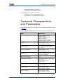
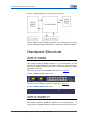
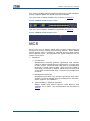
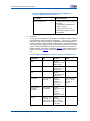
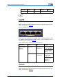
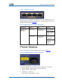
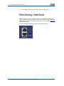
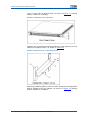
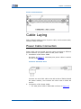
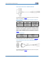
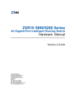
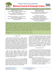
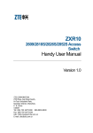
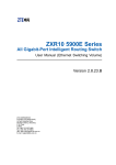
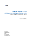
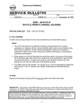
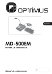
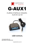
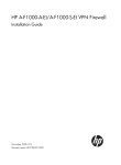
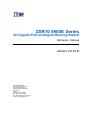
ZXR10 5900E Series
All Gigabit-Port Intelligent Routing Switch
Hardware Manual
Version 2.8.23.B
ZTE CORPORATION
ZTE Plaza, Keji Road South,
Hi-Tech Industrial Park,
Nanshan District, Shenzhen,
P. R. China
518057
Tel: (86) 755 26771900
Fax: (86) 755 26770801
URL: http://ensupport.zte.com.cn
E-mail: [email protected]
LEGAL INFORMATION
Copyright © 2006 ZTE CORPORATION.
The contents of this document are protected by copyright laws and international treaties. Any reproduction or distribution of
this document or any portion of this document, in any form by any means, without the prior written consent of ZTE CORPORATION is prohibited. Additionally, the contents of this document are protected by contractual confidentiality obligations.
All company, brand and product names are trade or service marks, or registered trade or service marks, of ZTE CORPORATION
or of their respective owners.
This document is provided “as is”, and all express, implied, or statutory warranties, representations or conditions are disclaimed, including without limitation any implied warranty of merchantability, fitness for a particular purpose, title or non-infringement. ZTE CORPORATION and its licensors shall not be liable for damages resulting from the use of or reliance on the
information contained herein.
ZTE CORPORATION or its licensors may have current or pending intellectual property rights or applications covering the subject
matter of this document. Except as expressly provided in any written license between ZTE CORPORATION and its licensee,
the user of this document shall not acquire any license to the subject matter herein.
ZTE CORPORATION reserves the right to upgrade or make technical change to this product without further notice.
Users may visit ZTE technical support website http://ensupport.zte.com.cn to inquire related information.
The ultimate right to interpret this product resides in ZTE CORPORATION.
Revision History
Revision No.
Revision Date
Revision Reason
R1.0
Nov. 9, 2009
First Release
Serial Number: sjzl20096391
Contents
About This Manual.............................................. i
Safety Introduction ...........................................1
Safety Introduction ......................................................... 1
Safety Symbols .............................................................. 1
System Introduction .........................................3
Product Overview ........................................................... 3
Functions ...................................................................... 3
Technical Characteristics and Parameters ........................... 5
Structure and Principle......................................7
Working Principle............................................................ 7
Hardware Structure ........................................................ 8
ZXR10 5928E............................................................. 8
ZXR10 5928E-FI......................................................... 8
MCS ............................................................................. 9
LIC ..............................................................................12
QXFB .......................................................................12
QGLB .......................................................................12
Power Module ...............................................................13
Monitoring Interface ......................................................14
Installation ..................................................... 15
Equipment Installation ...................................................15
Desktop Installation ...................................................15
Cabinet Installation....................................................15
Cable Laying .................................................................17
Power Cable Connection .............................................17
Connection of Serial Console Cable ..............................19
Connection of Network Cable ......................................20
Connection of Fiber....................................................21
Power-on Procedures .................................................22
Figures ............................................................ 25
Tables ............................................................. 27
Glossary .......................................................... 29
About This Manual
Purpose
Intended
Audience
What Is in This
Manual
Related
Documentation
This manual is ZXR10 5900E (V2.8.23.B) Series All Gigabit-Port
Intelligent Routing Switch Hardware Manual . This manual introduces structure and principle of 5900E, structure and principle of
board, power module and installation procedure.
This manual is intended for the following engineers:
�
on-site maintenance engineers
�
network monitor engineers
�
system maintenance engineer
ZXR10 5900E (V2.8.23.B) Series All Gigabit-Port Intelligent Routing Switch Hardware Manual contains the following chapters:
Chapter
Summary
Chapter 1 Safety
Introduction
This chapter describes the safety instructions
and signs.
Chapter 2 System
Introduction
This chapter describes the overview and
software and hardware features of ZXR10
5900E system.
Chapter 3 Structure
and Principle
This chapter describes ZXR10 5900E
structure and principles and each module of
system in detail.
Chapter 4 Installation
This chapter describes ZXR10 5900E
installation procedure.
�
ZXR10 5900E (V2.8.23.B) Series All Gigabit-Port Intelligent
Routing Switch Hardware Manual
�
ZXR10 5900E (V2.8.23.B) Series All Gigabit-Port Intelligent
Routing Switch User Manual (Basic Configuration Volume)
�
ZXR10 5900E (V2.8.23.B) Series All Gigabit-Port Intelligent
Routing Switch User Manual (Ethernet Switching Volume)
�
ZXR10 5900E (V2.8.23.B) Series All Gigabit-Port Intelligent
Routing Switch User Manual (IPv4 Routing Volume)
�
ZXR10 5900E (V2.8.23.B) Series All Gigabit-Port Intelligent
Routing Switch User Manual (IPv6 Routing Volume)
Confidential and Proprietary Information of ZTE CORPORATION
i
ZXR10 5900E Series Hardware Manual
This page is intentionally blank.
ii
Confidential and Proprietary Information of ZTE CORPORATION
Chapter
1
Safety Introduction
Table of Contents
Safety Introduction............................................................. 1
Safety Symbols .................................................................. 1
Safety Introduction
Only qualified professionals are allowed to perform installation,
operation and maintenance due to the high temperature and high
voltage of the equipment.
It is necessary to conform to local safety codes and relevant operation procedures during equipment installation, operation and
maintenance to prevent personal injury or equipment damage.
Safety precautions introduced in this manual are supplementary
to the local safety codes.
ZTE bears no responsibility in case of universal safety operation
requirements violation and safety standards violation in designing,
manufacturing and equipment usage.
Safety Symbols
When configuring ZXR10 5900E, it needs to pay attention to some
items. In this case, the following symbols are used:
Caution:
It indicates fault can occur if operator pays no attention to security
precautions.
Note:
It indicates other noted items besides safety introduction.
Confidential and Proprietary Information of ZTE CORPORATION
1
ZXR10 5900E Series Hardware Manual
This page is intentionally blank.
2
Confidential and Proprietary Information of ZTE CORPORATION
Chapter
2
System Introduction
Table of Contents
Product Overview ............................................................... 3
Functions .......................................................................... 3
Technical Characteristics and Parameters ............................... 5
Product Overview
ZXR10 5900E is a type of small-sized L3 Ethernet switch conforming to ETSI. It features compact structure and eco-friendly. The
switch targets at access layer of enterprise network and broadband IP MAN, provides Ethernet middle/low-density ports, and fits
for being used as user-side access device of informationized intelligent residential block, office building, hotel, campus network
and enterprise network or being used as convergence device of
small size networks to provide user with high-speed, efficient, high
price/performance ratio convergence solution.
ZXR10 5928E can provide 24 gigabit fast Ethernet electrical interfaces and ZXR10 5928E-FI can provide 24 gigabit fast Ethernet optical interfaces. Both of them support L2~L3 wire-speed
switching and hardware supports IPv6 route translation and IPv4IPv6 translation. They provide full support of Ethernet protocol
suite and efficient QOS priority mechanism, show flexible management, support complete L3 routing protocols, and provide four
10Gbps–24Gbps upstream/stack interfaces.
ZXR10 5900E has the following features:
�
High reliability and availability
�
Full line rate forwarding and filtering capabilities
�
Full support of network protocols
�
Open system architecture, showing good upgrade capability
Functions
ZXR10 5900E Series includes two models: ZXR10 5928E and
ZXR10 5928E-FI. Both two models use the same solution.
1. Physical Interface
Confidential and Proprietary Information of ZTE CORPORATION
3
ZXR10 5900E Series Hardware Manual
�
Supporting port rate, duplex mode and adaption configurations
�
Supporting port mirroring
�
Supporting suppression of broadcast storm
�
Supporting line diagnosis & analysis
2. VLAN
�
Supporting port-based VLAN
�
Supporting IEEE 802.1Q, allowing up to 4094 VLANs
�
Supporting PVLAN
�
Supporting VLAN double-tag
�
Supporting SuperVLAN
3. L2 Protocol
�
Supporting STP, RSTP and MSTP
�
Supporting static Trunk and LACP
�
Supporting IGMP Snooping
4. Routing Protocol
�
�
Supporting static route, RIP v1/v2, OSPF, IS-IS, BGP and
other unicast protocols
Supporting IGMP v1/v2, PIM-SM, MSDP and other multicast
protocols
5. ACL
�
�
Supporting basic ACL, extended ACL, L2 ACL and hybrid
ACL
Supporting ACL time range limit
6. QoS
�
Supporting 802.1p
�
Supporting SP and WRR queue scheduling modes
�
Supporting traffic monitoring
�
Supporting flow-based redirection
�
Supporting flow mirroring and traffic statistics
7. Access Authentication
�
Supporting RADIUS Client
�
Supporting DHCP Relay and DHCP Server
8. Reliability
�
Supporting VRRP
�
Supporting route load balancing
9. Network Management
�
�
4
Supporting Command Line Interface (CLI) configuration
mode
Supporting configuration through console port, Telnet and
SSH
Confidential and Proprietary Information of ZTE CORPORATION
Chapter 2 System Introduction
�
Supporting SNMP and RMON
�
Supporting ZTE NetNumen N31
10. Supporting monitoring interface
�
Supporting 3 dry node signal input
�
Supporting 5 dry node signal output
Technical Characteristics
and Parameters
Technical characteristics and parameters of ZXR10 5900E are listed
in Table 1.
TABLE 1 ZXR10 5900E TECHNICAL CHARACTERISTICS
AND
PARAMETERS
Item
Description
Dimensions
ZXR10 5928E: 43.6mm
(Height)×442mm
(Width)×220mm (depth)
ZXR10 5928E-FI:
43.6mm (Height)×442mm
(Width)×220mm (depth)
Weight
ZXR10 5928E: 4.8kg
ZXR10 5928E-FI: 4.8kg
Power Supply
AC: 100V~240V, 50Hz~60Hz
DC: –48V
Power Consumption
ZXR10 5928E: <55w
ZXR10 5928E-FI: <65w
MTBF: >200000 Hours
Reliability
MTTR: <30 Minutes
Lightning Protection
4KV
Working Temperature
Operating ambient temperature:
-5℃~+45℃
Storage temperature:
-40℃~+70℃
Working Humidity
Relative humidity: 10% to 90%,
non-condensing
Memory Size
ZXR10 5928E: 256M
ZXR10 5928E-FI: 256M
Switch Capacity
ZXR10 5928E: 128G
ZXR10 5928E-FI: 128G
Confidential and Proprietary Information of ZTE CORPORATION
5
ZXR10 5900E Series Hardware Manual
Item
Description
Packet Forwarding Rate
ZXR10 5928E: 13.98M
ZXR10 5928E-FI: 13.98M
Number of Routing Table Entries
ZXR10 5928E: host route: IPv4
8K, IPv6 4K
Network segment route: IPv4
12K, IPv6 6K
Equivalence route: 8
ZXR10 5928E-FI: host route:
IPv4 8K, IPv6 4K
Network segment route: IPv4
12K, IPv6 6K
Equivalence route: 8
Capacity of MAC Address Table
ZXR10 5928E: 32K
ZXR10 5928E-FI: 32K
6
Confidential and Proprietary Information of ZTE CORPORATION
Chapter
3
Structure and Principle
Table of Contents
Working Principle................................................................ 7
Hardware Structure ............................................................ 8
MCS ................................................................................. 9
LIC ..................................................................................12
Power Module ...................................................................13
Monitoring Interface ..........................................................14
Working Principle
ZXR10 5900E series products cassette fast Ethernet switches developed by ZTE. This series switches adopt modular design and
have strong capability in service control and user management so
as to provide networking solutions to convergence of enterprise
network, IP MAN network and residential block. ZXR10 5900E
series products have powerful functions and sound performance.
According to system functions, the product contains the following modules: control module, switching module, interface module,
power module and monitoring module.
1. Control module: the module contains main processor and
some other external function chips and is used by system to
process various applications. It provides console port for data
manipulation and maintenance.
2. Switching module: the main part of switching module is packet
processor, used for processing and switching of packets sent
from ports;
3. Interface module: interface module is composed of interface
chip and corresponding peripheral circuits, mainly used for
connection to external users and packet forwarding.
4. Power module: the module adopts 220V AC and supports 1+1
backup and hot-swap to supply needed power to the other
components within the system.
5. Monitoring module: Supporting 3 dry node signal input and 5
dry node signal output.
ZXR10 5900E system schematic diagram is shown in Figure 1.
Confidential and Proprietary Information of ZTE CORPORATION
7
ZXR10 5900E Series Hardware Manual
FIGURE 1 ZXR10 5900E SYSTEM SCHEMATIC DIAGRAM
ZXR10 5900E system adopts standard 19-inch plug-in box, which
can be installed outside separately or within the standard cabinet.
Hardware Structure
ZXR10 5928E
The height of ZXR10 5928E chassis is 1U (1U=44.45mm). It can
provide 24 gigabit Ethernet electrical interfaces (RJ45) and support CAT5 or above twisted pair cable, as well as QXFB and QGLB
upstream subcards.
The front view of ZXR10 5928E is as shown in Figure 2.
FIGURE 2 ZXR10 5928E FRONT VIEW
The rear view of ZXR10 5928E is as shown in Figure 3.
FIGURE 3 ZXR10 5928E REAR VIEW
ZXR10 5928E-FI
The height of ZXR10 5928E-FI chassis is 1U (1U=44.45mm). It
can provide 24 gigabit Ethernet optical interfaces (SFP) and sup-
8
Confidential and Proprietary Information of ZTE CORPORATION
Chapter 3 Structure and Principle
port various gigabit optical modules conforming to SFP standard.
It also supports QXFB and QGLB upstream subcards.
The front view of ZXR10 5928E-FI is as shown in Figure 4.
FIGURE 4 ZXR10 5928E-FI FRONT VIEW
The rear view of ZXR10 5928E-FI is as shown in Figure 5.
FIGURE 5 ZXR10 5928E-FI REAR VIEW
MCS
MCS is the core of ZXR10 5900E and it mainly implements the
functions of control module and switching module. As for ZXR10
5900E system, MCS is installed in cassette structure and doesn't
have separate panel. Its interfaces and signal indicators are on
system front panel.
1. Interfaces
i. Console Port
Management terminal perform operations and maintenance to ZXR10 5900E through Console port. Console port
is RJ45 socket, connected with COM port on management
terminal by serial console cable. One end of the cable is
RJ45 plug, connected to ZXR10 5900E and the other end
of the cable is DB9 female plug, connected to management
terminal.
ii. Management Interface
Management terminal can perform operations and maintenance to ZXR10 5900E through management interface,
which supports 10/100Base-T.
iii. 100/1000Base-T Ethernet Interface
ZXR10 5928E main board supports 1000 Base-TX and
100Base-TX on CAT5. The characteristics are as shown in
Table 2.
Confidential and Proprietary Information of ZTE CORPORATION
9
ZXR10 5900E Series Hardware Manual
TABLE 2 ZXR10 5900E MAIN BOARD 100/1000BASE-T
ETHERNET INTERFACE CHARACTERISTICS
Port Type
Characteristics
100/1000Base-TX
• Conforming to the following
standards:
• 1000BASE-TX IEEE 802.3u
• RJ45 Connector
• Using CAT5 UTP, max
transmission distance 100m
• MDI/MDIX
2. Indicator
There are 29 indicators on front panel of ZXR10 5900E, where
24 indicators are port status indicators. There are 4 system
indicators STA, SPD, DUP and SYS/ALM and 1 management interface indicator. By pressing mode button, 24 port indicators
can switch their display modes: SPD mode, DUP mode or STA
mode. ZXR10 5900EAC-DC power module has two indicators:
RUN indicator and FAULT indicator.Table 3 shows functions of
system indicator.Table 4 shows functions of port status indicator.
TABLE 3 ZXR10 5900E SYSTEM INDICATOR FUNCTION DESCRIPTION
Indicator
Off
Green
Red
SPD
/
Green
indicator is on:
SPD mode
/
DUP
/
Green
indicator is on:
DUP mode
/
STA
/
Green
indicator is on:
STA mode
/
SYS/ALM
Device is not
powered
Green
indicator
flashes:
Device runs
normally
Red indicator
is on: Fault
occurs on
device
Management
Interface
Indicator
Connection is
unavailable.
Green
indicator is on:
link
/
Green
indicator
flashes: active
RUN
10
Device is not
powered or
fault occurs on
power source
Confidential and Proprietary Information of ZTE CORPORATION
Green
indicator is
on: Power
source works
normally
/
Chapter 3 Structure and Principle
Indicator
Off
Green
Red
FAULT
/
/
Red indicator
is on: Power
temperature
alarm is
generated or
fault occurs on
power source.
TABLE 4 ZXR10 5900E PORT STATUS INDICATOR FUNCTION
DESCRIPTION
Indicator
Mode
Off
Green
Yellow
24 gigabit
Port
Indicators
SPD mode
Connection
is unavailable.
Green
indicator is
on: 1000M
link
Yellow
indicator is
on: 100M
link
Green
indicator
flashes:
1000M
active
Yellow
indicator
flashes:
100M
active
Green
indicator
is on:
Full-duplex
link
Yellow
indicator
is on:
Half-duplex
link
Green
indicator
flashes:
Full-duplex
active
Yellow
indicator
flashes:
Half-duplex
active
Green
indicator is
on: link
Yellow
indicator
is on:
Packets
fail to be
forwarded
since STP
port is
blocked.
Green
indicator
flashes:
active
Yellow
indicator
flashes:
Packets
are being
forwarded
and STP
port is
blocked.
DUP mode
STA mode
Connection
is unavailable.
Connection
is unavailable.
Green and yellow
indicators flash:
Connection error, frame
Confidential and Proprietary Information of ZTE CORPORATION
11
ZXR10 5900E Series Hardware Manual
Indicator
Mode
Green
Yellow
error CRC error and so
on.
Off
LIC
QXFB
QXFB subcard provides 4 gigabit Ethernet upstream optical interfaces, as shown in Figure 6.
FIGURE 6 QXFB FRONT VIEW
There are four indicators on QXFB panel, corresponding to four
10 gigabit optical interfaces respectively. The description of four
indicators is as shown in Table 5.
TABLE 5 QXFB INDICATOR FUNCTION DESCRIPTION
Indicator
Mode
Off
Green
QXFB Gigabit
Optical
Interface
SPD mode
Connection is
unavailable.
Green indicator
is on: 10G link
Green indicator
flashes: 10G
active
DUP mode
Connection is
unavailable.
Green indicator
is on: Fullduplex link
Green indicator
flashes:
Full-duplex
active
QGLB
QGLB subcard provides 4 gigabit Ethernet upstream optical interfaces, as shown in Figure 7.
12
Confidential and Proprietary Information of ZTE CORPORATION
Chapter 3 Structure and Principle
FIGURE 7 QGLB FRONT VIEW
There are four indicators on QGLB panel, corresponding to four
gigabit optical interfaces respectively. The description of four indicators is as shown in Table 6.
TABLE 6 QGLB INDICATOR FUNCTION DESCRIPTION
Indicator
Mode
Off
Green
QGLB Gigabit
Optical
Interface
SPD mode
Connection is
unavailable.
Green indicator
is on: 1G link
Green indicator
flashes: 1G
active
DUP mode
Connection is
unavailable.
Green indicator
is on: Fullduplex link
Green indicator
flashes:
Full-duplex
active
Power Module
The power panel of ZXR10 5900E is as shown in Figure 8
FIGURE 8 5900E AC POWER INTERFACE DIAGRAM
Technical parameters of AC-DC power module are as follows:
�
Input voltage: single-phase 100VAC–240VAC
�
Input current: Max 1.42A
�
Frequency: 43–67Hz
�
Max Power Consumption: 100W
Confidential and Proprietary Information of ZTE CORPORATION
13
ZXR10 5900E Series Hardware Manual
�
Line voltage waveform deviation factor (WDF)<5%
Monitoring Interface
ZXR10 5900E provides 2 RJ45 interfaces. ALARM IN interface provides a pair of dry node input and 3 pairs of dry node input and
ALARM OUT interface provides 4 pairs of dry node output.Figure 9
shows interfaces.
FIGURE 9 ZXR10 5900E MONITORING INTERFACE DIAGRAM
14
Confidential and Proprietary Information of ZTE CORPORATION
Chapter
4
Installation
Table of Contents
Equipment Installation .......................................................15
Cable Laying .....................................................................17
Equipment Installation
Similar to installation of ZXR10 5952A, ZXR10 5900E series switch
can be installed both on desktop and in 19-inch standard cabinet.
Where, 19-inch standard cabinet can be provided by the user. In
case ZTE cabinet is to be used, please refer to 19-Inch Standard
Cabinet Installation Manual for cabinet installation.
Desktop Installation
When installing switch on desktop, install four plastic bottom
blocks (plastic bottom blocks are strews are provided together
with device) on the bottom plate of switch to form an air passage,
for which heat generated by power module can be dissipated
efficiently. The detailed installation is shown in Figure 10 (taking
ZXR10 5952A for example).
FIGURE 10 5952A DESKTOP INSTALLATION
Cabinet Installation
To install ZXR10 5900E series switch onto 19-inch cabinet, fix two
flanges (both flanges and screws are provided together with de-
Confidential and Proprietary Information of ZTE CORPORATION
15
ZXR10 5900E Series Hardware Manual
vice) on two sides of switch shell, as shown inFigure 11 (taking
ZXR10 3252A for example).
FIGURE 11 INSTALLATION
OF
FLANGES
Install a pair of symmetric holding plates on inner sides of 19-inch
cabinet to support switch, as shown in Figure 12.
FIGURE 12 INSTALLATION
OF
HOLDING PLATES
After fixing holding plates, push in switch along the holding plates
and fix flanges onto the cabinet, as shown in Figure 13 (taking
ZXR10 3252A for example).
16
Confidential and Proprietary Information of ZTE CORPORATION
Chapter 4 Installation
FIGURE 13 FIXING DEVICE
Cable Laying
ZXR10 5900E cables consist of power cable, serial console cable,
network cable and fiber.
Power Cable Connection
Power cable can be divided into two types according to different
power modules: AC power cable and DC power cable.
1. Connection of AC Power Cable
As shown in Figure 14, standard print power cable is used as
the AC power cable.
FIGURE 14 AC POWER CABLE
Connect one end of AC cable to the AC socket of ZXR10 5900E
AC power module, and connect the other end to 220V AC
socket.
2. Connection of DC Power Cable
i. DC -48V power cable C-PWR-084 is shown in Figure 15.
Confidential and Proprietary Information of ZTE CORPORATION
17
ZXR10 5900E Series Hardware Manual
FIGURE 15 DC POWER CABLE C-PWR-084 DIAGRAM
Corresponding relationship between two ends of DC power
cable is as shown in Table 7.
TABLE 7 CORRESPONDING RELATIONSHIP
DC POWER CABLE
BETWEEN
TWO ENDS
OF
End A
End B
Power Signal
1
End B1
-48V GND
2
End B2
-48V
End A is connected to -48V input socket of device, and two
terminals on end B shall be connected according to labels
pasted on each conductor, where B1 is connected to DC
power supply -48VGND and B2 is connected to DC power
supply -48V. The details on B1 and B2 labels are shown in
Table 8.
TABLE 8 LABEL DETAILS
End B1
End B2
-48V GND
-48V
ii. DC backup power cable C-PWR-072 is shown in Figure 16.
FIGURE 16 DC BACKUP POWER CABLE C-PWR-072 DIAGRAM
Corresponding relationship between two ends of DC power
cable is as shown in Table 9.
18
Confidential and Proprietary Information of ZTE CORPORATION
Chapter 4 Installation
TABLE 9 CORRESPONDING RELATIONSHIP
DC POWER CABLE
BETWEEN
TWO ENDS
OF
End A
Conductor
Colour
End B
Power
Signal
1
Black
B1
12V (-)
2
Black (Red
Sleeve)
B2
12V (+)
Determine whether to connect this backup DC power cable
according to configuration requirements. In installation,
connect end A to the backup DC input socket of device,
connect end B1 to cathode of external 12V power source,
and connect end B2 with red sleeve to anode of external
12V power source.
Connection of Serial Console Cable
Serial console cable is the basic cable used in configuring and
maintaining ZXR10 5900E.
Serial configuration line is provided together with ZXR10 5900E
one end to be DB9 console port (connected to serial port of PC)
and the other end to be RJ45 port (connected to Console port on
main Board of ZXR10 5900E ).
The serial console cable is shown in Figure 17.
FIGURE 17 ZXR10 5900E SERIAL CONSOLE CABLE DIAGRAM
Line order of serial console cable is shown in Table 10.
TABLE 10 SERIAL CONSOLE CABLE LINE ORDER TABLE
End A
Cable Chromatogram
End B
2
White
3
3
Blue
6
White
4
Orange
5
5
Confidential and Proprietary Information of ZTE CORPORATION
19
ZXR10 5900E Series Hardware Manual
End A
Cable Chromatogram
End B
4
White
7
6
Green
2
7
White
8
8
Brown
1
Connection of Network Cable
RJ45 plugs are crimped on both ends of the cable with the structure
as shown in Figure 18.
�
Cable plug name: 8P8C straight cable solder plug
�
Specification: E5088-001023
�
technical parameters: rated current: 1.5, rated voltage: 125V,
crimped with AWG24-28# wire gauge round cable.
FIGURE 18 NETWORK CABLE STRUCTURE DIAGRAM
Cables can be classified into the following two types according to
different cable crimping order in the plug:
�
Straight-through network cable RJ45: the cable connection relationship is in the one-to-one correspondence at both ends.
The specific connection relationship is shown in Table 11.
TABLE 11 STRAIGHT-THROUGH NETWORK CABLE RJ45 LINE ORDER
TABLE
20
End A
Cable Chromatogram
End B
1
White-Orange
1
2
Orange
2
3
White-Green
3
6
Green
6
4
Blue
4
5
White-Blue
5
Confidential and Proprietary Information of ZTE CORPORATION
Chapter 4 Installation
�
End A
Cable Chromatogram
End B
7
White-Brown
7
8
Brown
8
Crossover network cable RJ45J: cable connection relationship
is cross correspondence between two twisted pairs at both
ends. The specific connection relationship is shown in Table
12.
TABLE 12 CROSSOVER NETWORK CABLE RJ45J LINE ORDER TABLE
End A
Cable Chromatogram
End B
1
White-Orange
3
2
Orange
6
3
White-Green
1
6
Green
2
4
Blue
4
5
White-Blue
5
7
White-Brown
7
8
Brown
8
Connection of Fiber
There are two fibers for each ZXR10 5900E optical interface. One
is used for receiving packets and the other is used for sending
packets. Pay attention to TX and RX marks on the panel and never
insert wrong ends. Two types of fibers are available: single-mode
fiber and multi-mode fiber. User can configure the fiber according
to the actual application.Table 13 shows 6 types of fiber.
TABLE 13 FIBER TYPE TABLE
Mode
Switch End
Connector Type
Opposite End
Connector Type
FC/PC Connector
Single-mode fiber
SC-PC Connector
(Square Panhead)
SC/PC Connector
ST/PC Connector
Multi-Mode Fiber
SC-PC Connector
(Square Panhead)
FC/PC Connector
SC/PC Connector
Confidential and Proprietary Information of ZTE CORPORATION
21
ZXR10 5900E Series Hardware Manual
Switch End
Connector Type
Mode
Opposite End
Connector Type
ST/PC Connector
As for fiber out of the cabinet, make sure to protect the fiber
against any damages with plastic corrugated sleeve. The fiber
within the protect sleeve must not be wound up and the corners
must be radian. The labels at two ends of the fiber must be clear.
The meaning of the label must correctly reflect corresponding serial numbers and relationship between cabinets and between rows.
Power-on Procedures
Check environment in lab and hardware installation before
power-on ZXR10 5900E.
1. Check whether lab temperature, humidity and voltage meet
the installation requirements, as shown in Table 14.
TABLE 14 TEMPERATURE
AND
HUMIDITY
Temperature (℃)
Item
Scope
1.
2.
Relative Humidity (%)
Long-Term
Working
Condition
(Note 1)
Short-Term
Working
Condition
(Note 2)
Long-Term
Working
Condition
Short-Term
Working
Condition
15℃~30℃
-5℃~45℃
30%~70%
20%~90%
When ZXR10 5900E works in normal environment, temperature and
humidity measurement points refer to values measured at points 2m
above the floor and 0.4m in front of equipment (they must be measured
when there is no protection plate in front and back of cabinet).
Short-term working conditions refer to less than 48 continuous hours
and less than 15 accumulated days per year.
2. Check if power cable and other cables are connected correctly
and reliably.
3. Check other hardware.
i. Check if devices are labeled completely, correctly and
clearly.
ii. Check if switch is firmly installed in 19-inch standard rack
or if it is stably installed on desktop.
iii. Check if power switch of switch is at off position.
iv. Check if rack has a good contact and if earthing resistance
meets technical requirements.
4. Power on ZXR10 5900E in the following steps:
i. Connect switch AC power cable.
22
Confidential and Proprietary Information of ZTE CORPORATION
Chapter 4 Installation
ii. Turn on external power supply.
5. Power off ZXR10 5900E in the following steps:
i. Turn off external power supply.
ii. Disconnect switch AC power cable.
Confidential and Proprietary Information of ZTE CORPORATION
23
ZXR10 5900E Series Hardware Manual
This page is intentionally blank.
24
Confidential and Proprietary Information of ZTE CORPORATION
Figures
Figure 1 ZXR10 5900E System Schematic Diagram ................. 8
Figure 2 ZXR10 5928E Front View......................................... 8
Figure 3 ZXR10 5928E Rear View.......................................... 8
Figure 4 ZXR10 5928E-FI Front View..................................... 9
Figure 5 ZXR10 5928E-FI Rear View...................................... 9
Figure 6 QXFB Front View ...................................................12
Figure 7 QGLB Front View ...................................................13
Figure 8 5900E AC Power Interface Diagram .........................13
Figure 9 ZXR10 5900E Monitoring Interface Diagram..............14
Figure 10 5952A Desktop Installation ...................................15
Figure 11 Installation of Flanges ..........................................16
Figure 12 Installation of Holding Plates .................................16
Figure 13 Fixing Device ......................................................17
Figure 14 AC Power Cable...................................................17
Figure 15 DC Power Cable C-PWR-084 Diagram .....................18
Figure 16 DC Backup Power Cable C-PWR-072 Diagram ..........18
Figure 17 ZXR10 5900E Serial Console Cable Diagram............19
Figure 18 Network Cable Structure Diagram ..........................20
Confidential and Proprietary Information of ZTE CORPORATION
25
ZXR10 5900E Series Hardware Manual
This page is intentionally blank.
26
Confidential and Proprietary Information of ZTE CORPORATION
Tables
Table 1 ZXR10 5900E Technical Characteristics and Parameters .. 5
Table 2 ZXR10 5900E Main Board 100/1000Base-T Ethernet
Interface Characteristics .....................................10
Table 3 ZXR10 5900E System Indicator Function Description ...10
Table 4 ZXR10 5900E Port Status Indicator Function
Description .......................................................11
Table 5 QXFB Indicator Function Description..........................12
Table 6 QGLB Indicator Function Description .........................13
Table 7 Corresponding Relationship between Two Ends of DC
Power Cable......................................................18
Table 8 Label Details ..........................................................18
Table 9 Corresponding Relationship between Two Ends of DC
Power Cable......................................................19
Table 10 Serial Console Cable Line Order Table ......................19
Table 11 Straight-Through Network Cable RJ45 Line Order
Table ...............................................................20
Table 12 Crossover Network Cable RJ45J Line Order Table.......21
Table 13 Fiber Type Table....................................................21
Table 14 Temperature and Humidity .....................................22
Confidential and Proprietary Information of ZTE CORPORATION
27
ZXR10 5900E Series Hardware Manual
This page is intentionally blank.
28
Confidential and Proprietary Information of ZTE CORPORATION
Glossary
BGP
- Border Gateway Protocol
IGMP
- Internet Group Management Protocol
IS-IS
- Intermediate System-to-Intermediate System
LACP
- Link Aggregation Control Protocol
MSDP
- Multicast Source Discovery Protocol
MSTP
- Multiple Spanning Tree Protocol
OSPF
- Open Shortest Path First
PIM-SM
- Protocol Independent Multicast - Sparse Mode
PVLAN
- Private Virtual Local Area Network
QoS
- Quality of Service
RADIUS
- Remote Authentication Dial In User Service
RIP
- Routing Information Protocol
RMON
- Remote Monitoring
RSTP
- Rapid Spanning Tree Protocol
SNMP
- Simple Network Management Protocol
SP
- Strict Priority
SSH
- Secure Shell
STP
- Spanning Tree Protocol
VLAN
- Virtual Local Area Network
VRRP
- Virtual Router Redundancy Protocol
WRR
- Weighted Round Robin
Confidential and Proprietary Information of ZTE CORPORATION
29