1
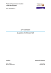
Halny: a Digital Signal Processor Based
Module for the Readout of Silicon Strip
Detectors
E. Banas, A. Bo_zek, P. Jalocha, P. Kapusta, 1
Z.Natkaniec, W. Ostrowicz, H. Palka, and M. Roz_ anska
Henryk Niewodniczanski Institute of Nuclear Physics, ul.Kawiory 26A 30-055
Krakow, Poland
D. Marlow
Joseph Henry Laboratories, Princeton University, Princeton NJ, 08544 USA
M. Tanaka
High Energy Accelerator Research Organization, 1-1 Oho, Tsukuba, Ibaraki-ken,
305 Japan
Abstract
We describe a four-channel, digital-signal-processor-based readout board, equipped
with analog-to-digital converters. A series of identical boards work in parallel in the
BELLE experiment at KEK, performing a zero-suppressing readout of the silicon
vertex detector. A cluster-searching algorithm executes quickly enough to allow dead
time-free readout at a 500 Hz trigger rate. DSP code downloaded to the boards can
be easily modied, aording a high degree of exibility. We describe the board
hardware, the algorithms employed in the experiment, and the software used to
implement them.
1 Introduction
The Silicon Vertex Detector (SVD) of the BELLE (1) experiment at KEK
consists of 81,920 channels and is foreseen to operate at trigger rates up to
1
Corresponding author. E-mail address: [email protected]
Preprint submitted to Elsevier Preprint
4 May 2000
500Hz (2). Since the number of strips is large and the VA1 chips (3) used
in the detector are not capable of on-chip zero suppression, an external datareduction system is necessary. Based on experience with a similar system from
the DELPHI experiment (4) (5), data reduction using digital signal processors
(DSP)s has been chosen.
In the BELLE SVD, signals from the strips are amplied, shaped, and stored
by VA1 front-end chips mounted in close proximity to the detector. The stored
analog signals are routed to the HALNY modules in sequence using an onchip scanning analog multiplexer. Buering of the analog signals and various
control signals is provided by a repeater system, (6) located at an intermediate
point between the SVD and the electronics hut where the HALNY boards are
situated.
After common-mode uctuations 2 are corrected, a cluster-searching process is
executed using pulse-height information together with individually calculated
strip pedestals and widths. Finally, events are built in a compressed format.
Compared with pipelined systems based, for example, on eld-programmable
gaeld-programmable gate arrays, the use of DSPs oers the following advantages:
dynamic pedestal updating;
discrimination based on strip-by-strip signal-to-noise ratio;
autonomous elimination of dead and noisy channels;
exibility in programming;
The main disadvantage of using DSPs is the long and variable processing time.
This implies necessity of queuing events before passing them to DSPs.
2 Module Description
2.1 General
The HALNY 3 is a single-width 6U VME module used for readout of multiplexed analog signals. It houses four independent channels, each consisting
of an analog input block and a DSP-based processing unit. The analog input
blocks accept dierential analog signals from the module's front panel. These
Common-mode uctuations refer to coherent-noise eects that aect all strips in
the same manner in a given event.
3 The word \Halny" is the Polish name for a warm wind blowing through the Tatra
mountains.
2
2
signals are amplied, level-shifted and fed to ADCs. The ADC sensitivity is
xed at 2 mV/count. Digitized values are passed from the ADC block to the
processing unit through a rst-in-rst-out (FIFO) buer memory. This input
FIFO serves to derandomize the arrival times of incoming data, allowing the
system to cope with instantaneous rates that exceed its average rate-handling
capability. The DSPs pass the processed data to output FIFOs where they
can be read out via the VME backplane. The output FIFOs allow event processing in the DSPs and readout by the main data-acquisition (DAQ) system
to proceed asynchronously.
Every channel of the module incorporates the following functionality:
a dierential analog input with xed amplication;
a level shifter controlled by a 12-bit DAC;
10-bit ADC converter;
conversion rate up to 10 MHz;
an 8K-sample-deep FIFO;
a Motorola DSP56302 processor running with a 66 MHz clock ;
an 8K-deep16 bit output FIFO.
2.2 Module Operation
With each occurrence of an external clock signal, sampled data from the ADC
are written to the derandomizing input FIFO. Ten bits of pulseheight data are
accompanied by externally-supplied start and stop event markers and four bits
of event-tagging information. The DSP reads these data from the FIFO, carrying out the necessary processing steps (common mode correction, pedestal
subtraction, noise calculation, cluster searching etc.) as it goes. Results are
written to the output FIFO, where they are subsequently read via the VME
bus. To speed up the VME transfers, 16-bit-wide words from the DSP are
multiplexed into 32-bit words.
Proper operation of the module requires the ability to block additional signals
when the FIFO buers ll (a rare occurrence under normal conditions). This
is accomplished by sending a BUSY signal derived from the programmable
ALMOST-FULL state of the FIFOs. The BUSY signals from the HALNY
modules in the system are wire ORed together and forwarded to the experiment's global trigger system. Thus a full buer anywhere in the system inhibits
new triggers.
Each output FIFO is accompanied by a 12-bit up-down counter, which the
DSP increments when a new event has been passed to the output FIFO. A
non-zero state of the counter can be recognized by reading the VME status
register and readout of a full event can be performed. Upon completion of the
3
event readout the counter is decremented via a dened VME operation. Since
each event consists of at least two 16-bit words, a 12-bit counter is sucient
to manage the 8K-word output FIFO.
The HALNY module uses the VME P1 and P2 connectors and works in A32
mode, recognizing all (user/ supervisor ; data/block) address modiers. The
module's base address is xed by an 8-bit jumper (bits 31:24) and three rotary
switches (bits 12:23). The base address can be selected to lie in the range:
0x00000000 - 0xFFFFF000.
Data transfers occur in D32 mode. A block transfer readout mode of the
output FIFOs is available. The module does not house the VME interrupter.
2.3 Analog-to-Digital Conversion Block
A block diagram of a single ADC channel is shown in Fig.1. The heart of the
block is an AD9200 ADC 4 Four such ADC blocks are placed on a daughter
board, which is connected to the main board via three 64-pin miniature connectors. Two of these connectors are used for signals and the third is used for
power lines.
Four 14-mm dierential LEMO connectors are for the analog input signals.
The analog signals must lie within the range ;4 V
+4 V and must
have a dynamic swing of less than 2 V. The dierential input signals from
the receivers are converted to single-ended signals, and then amplied, level
shifted, and limited in HFA1135 current feedback op-amp. The oset voltage
used for level shifting comes from a DAC8043, which is 12-bit serial DAC
controlled by the DSP. Limiting is necessary to avoid damaging the AD9200.
The gain of the circuit is approximately unity and the ADC is set to operate
with 0-2 V input range. Due to the behavior of the limiting op-amp, the
linearity of the ADC block is aected near limits of its range.
< V
<
The AD9200 ADC requires a continuous convert clock with a 50% duty cycle.
It operates in a pipeline mode, with a four-clock-period latency between its
input sample and the appearance of the corresponding digital information on
its output.
AD9200, a complete 10-Bit, 20-MSPS, 80 mW CMOS A/D Converter, Analog
Devices, Inc.
4
4
Differential receiver
- OPA620
Amplifier and level-shifter
- HFA1135
Three-state buffers
Data
ADC
10
10
Control Signals Interface
AD9200
Convert Clock
Start of Event
Stop of Event
Busy
Tag
4
DAC CONTROL
Serial clock
and data
64-pin CMC connector
Enable
DAC
8043
-5V
+5V
+12V
-12V
-12V/-5V
voltage
converter
Fig. 1. Block diagram of the single ADC Block. Dashed shapes represents elements
shared between dierent ADC Blocks.
2.4 Processing Unit
Four identical processing units are placed on the main board. The heart of each
unit is the Motorola DSP56302 digital signal processor chip. The DSP56302
was selected for the following features:
large on-chip memories (20K24 bit of program memory, 14K24 bit of
data memory), eliminating the need for external memory, thereby saving
board space, lowering the costs, and reducing program execution times by
keeping the entire program in cache memory;
relatively high computational power|66 million instructions per second
(MIPS);
a small number of necessary external components;
object-code compatibility with the DSP56000, for which relevant software
5
already existed.
BUSY
DERANDOMIZER -INPUT
FIFO
4
AUXILIARY
LOGIC
Almost Full
Data
10
Reset
(8k x 16 fifo)
16
Counter
DSP
OUTPUT
FIFO
Port A
DAC
control
(8k x 16 fifo)
16
MUX
Reset
32
VME INTERFACE
Tag
Ports C , D
64-pin CMC connector
Convert Clock
Start of Event
Stop of Event
Write
Almost
Full
Up
+ 12-bit counter
Port B
Down
Not empty
3
Reset
Host Port Signals
10
DSP Status
Fig. 2. Block diagram of a single processing unit. Dashed shapes represent blocks
shared between dierent units.
Fig. 2 shows a general block diagram of the processing unit. Assertion of the
START-OF-EVENT signal begins the acquisition cycle, at which point 10
bits of ADC data, 4 bits of event tag information, and 2 bits of start/stop
event markers are written to the FIFO derandomizer at every active edge of
the convert clock. This process continues until STOP-OF-EVENT comes. The
derandomizer is implemented in a single Cypress CY7C4255 FIFO memory
chip (8k18 bit words). The FIFO collects a complete event from the ADC
block before passing it to the DSP. Assuming an event size of 1K sample and
assuming that the trigger rate is smaller than the average processing time per
event, the 8K sample depth of the FIFO is sucient to eectively eliminate
dead time associated with the event processing.
The STOP-OF-EVENT markers are counted by a counter inside the DSP. The
state of this counter is used for triggering readout from the derandomizer. In
this way, the DSP is able to acquire complete events with maximum speed,
6
without wasting processing power for polling.
The ALMOST-FULL output of the input FIFO is asserted when the occupancy of the derandomizer exceeds a preprogrammed level. Before data acquisition starts, this level is programmed by the DSP (the path is not shown
in the diagram) to be asserted when the FIFO has only enough space for
one more event. This ensures that that no overwriting will occur, even under
worst-case conditions, where the BUSY is asserted too late to block the next
trigger.
The CY7C4255 FIFO chip is also used for the output buer. A single VME
read of the output FIFO results in two read cycles, wherein data from two
samples are multiplexed into a single 32-bit-wide word. A 12-into a single 32bit-wide word. A 12-bit counter keeps track of the number of unread events
stored in the output FIFO. A non-zero state of this counter is reported in the
VME status register. To ensure a proper handshake between the VME and
the DSP, the following rules are obeyed:
the DSP increments the counter after an event has been transferred to the
output FIFO;
the VME decrements the counter after the event has been read out from
the module;
the DSP writes at least two 16-bit words for every event.
Normally the DSP signicantly reduces size of processed events. Thus a relatively large number of events can be stored in the output FIFO and its role
as a derandomizer between the DSP and the VME is not as critical as in the
case of the input FIFO.
Programs are downloaded to the DSP from the VME via host port lines. The
same lines can be used for execution software interrupts, which can be used
for accessing all DSP resources.
3 Algorithms
The rst objective of the DSP code is to subtract the signal components that
the o-line analysis does not want to see|i.e., the pedestals and the commonmode uctuations.
Pedestal values must be determined on a strip-by-strip basis. This is done by
computing a running average over several events of the value for each strip,
taking care to remove samples that dier appreciably from the average, so as
to minimize the impact of bona-de signals. Since the typical strip occupancy
7
DSP processing algorythm for the HALNY module
CN CM
<CN>
D
D-P
+
-
chan #0
D-P-CM
+
D-P-CM
N
+
-
+
Estimated common
noise value
D
Value read from the channel
of a silicon detector
S
Detector signal
after subtracting
unwanted components
S #1
F
Selection flag
F #1
T1
T2
Single-strip select threshold
F #0
+
-
+
+
-
+
-
-
P
CM estimator
+
1/N
+
-
+
P
1/N
+
+
Double-strip select threshold
Pedestal storage
and tracking
Noise reciprocial
storage and tracking
+
-
+
+
-
chan. #127
CN
+
1/N
chan. #1
Estimated common
mode value
S #0
-
P
CM
Adder
+
-
-
S #127
F #127
Multiplier
P
+
-
1/N
T1
Comparator
T2
Logical OR
Fig. 3. Processing ow inside the DSP.
is only 1%, such eects are generally not too severe.
Common-mode eects are estimated on an event-by-event basis for each group
of 128 strips, which corresponds to one readout chip. The common-mode uctuation is estimated by computing the average of the pedestal-subtracted values of all of the strips in a group. One again, care is taken to remove nonpedestal hits using RMS-based cuts to identify non-pedestal values.
The second objective of the algorithm is to reduce the amount of information by suppressing information from strips that do not to contain any useful
information. The selection is based on the signal-to-noise ratio measured on
each strip. It therefore requires that the expected noise variance on each strip
be measured. The noise-level estimation is done for each strip in a continuous
fashion, as was done for the pedestals, by computing the root-mean-square of
the strip data after pedestal and common-mode subtraction. Once again, care
is taken to remove bona de particle hits from the sample to be averaged.
8
The selection can now be done based on a predened signal-to-noise ratio
threshold, which is normally set to four. To improve the selection eciency
for particle signals distributed over several strips, the cut (with a threshold
that is a bit higher) is also applied to the sum of signals registered on two,
three and more consecutive strips.
All signals and groups of signals exceeding the threshold are marked for later
placement into the output record. The DSP can write output data in several
formats, with or without suppression, and with optional compression applied
to reduce the amount of data. The compression attempts to squeeze smaller
signals as well as the strip numbers into one byte instead of two. This normally
yields a compression factor of 1.2{1.5. Along with the signals, the data record
contains statistical information, which can serve to provide individual detector
health monitoring: the common mode and the RMS of each chip for every event
and the pedestal and noise estimations for every strip. This information is sent
in a round-robin fashion. In this way, by taking a sample of some 100 events,
one can get a complete picture of pedestals and noise in the system.
The DSP code is written in the assembler of the Motorola DSP56302A processor and takes some 2000 lines of assembler code and 1100 words when
compiled and loaded into the DSP. At the nominal processor speed of 66 MHz
(66 MIPS) the code reading 640 strips can analyze more than 500 events per
second.
For testing purposes, dedicated data formats are made to output raw ADC
data or the ADC data partially or fully analyzed but without any zero suppression.
4 Programming
The programming of a HALNY board is performed from two sides|the VME
crate controller and DSPs on the board. As some internal HALNY resources
are accessible either from the VME controller or from the DSP, the initialization of the board and steering during read-out is rather complex, requiring
proper scheduling and divided control between programs in both processors.
In this section, we describe the VME control programs.
The initialization (see Fig. 4) of the HALNY board consists of: reseting of
the analog board, reseting of the DSP, reseting of the 12-bit up-down counter,
programming of the output FIFO, and downloading of a DSP program code
to the DSPs. The programming of the derandomizers is done by the DSPs.
Because the code in a DSP starts its execution immediately after downloading,
9
START
Reset HALNY
Analog Daughter Board Reset
JTag Reset
Disable Trigger
4 times
Download code to DSP
Read DSP program - s-record file
Reset DSP channel
Download program code to DSP
through the DSP Host Port
NO
board status OK?
STOP
routine with
error code
YES
Reset Output FIFO
4 times
Reset DSP Event Counter
NO
board status OK?
YES
Set Identifier
STOP
Fig. 4. HALNY initialization and downloading DSPs.
10
it is very important to introduce synchronization mechanisms between the
DSP program and the VME controller program. The identier word plays the
role of a synchronizer: before taking action, the program in the DSP waits
until the VME controller program writes a proper identier word through a
DSP host port.
The board is exible enough to allow the downloading of a unique program to
each DSP. Each step of the initialization is controlled with regard to errors.
The readout procedure (see Fig. 5) is activated whenever there is a readyto-read event in the output FIFO. When there is a ready-to-read event in
the output FIFO, the contents of the 12-bit up-down counter become nonzero and a ag is set in the HALNY status register. The readout program
performs a simple polling of the status register while waiting for data and
initiates a readout sequence when the ags for all channels have been set.
During the readout sequence, the readout program takes one complete event
from each output FIFO in turn. As it reads the data it checks for proper start
and stop markers, proper event length, proper checksum word, and proper
tags. The checksum word was introduced to enhance the checking of events
in a straightforward way. The DSP calculates a checksum and puts it as the
last word in each event. The VME control program, after collecting all event
words, calculates a checksum using the same algorithm used in the DSP and
then checks it against the DSP-calculated value.
The VME control programs use a dedicated library, where the steps described
here and shown in the gures are implemented as a set of calls. The library
and the test-control programs have been written in standard ANSI C, running
on a SPARC CPU-7V (system SunOS 5.5). The library can be used by any
program written in C or C++.
5 PERFORMANCE
The stability of the board hardware under actual experimental conditions is
very high. The 32 modules in the system required almost no maintenance
during a year-long run of the experiment. At the presently achievable KEK-B
luminosity of 1 5 1033 cm;2s;1 the BELLE detector trigger rate is below
300 Hz. Under these conditions the readout speed (200 ns/strip) and processing time (1.9 ms/event) of the board are completely adequate. Extrapolating
to the maximum trigger rate of 500 Hz, we estimate a readout deadtime of
less than 10%, consistent with the original specication.
:
The data sparsication is also satisfactory. Under the current experimental
conditions, the board typically compresses data from the 81920 channels that
11
START
Enable trigger in HALNY
Read HALNY Status (flags from 12-bit counters)
NO
IF all flags
are set
YES
Read out entire board
4 times
Read one DSP channel
Read complete event
Perform checks of event correctness:
Start Event Marker
Stop Event Marker
Event Length
Control Checksum
STOP
routine with
error code
Event correct?
Decrement 12-bit counter
4 times
Check tag words in events from all DSPs
bad
correct
NO
Last event ?
YES
Disable trigger in HALNY
STOP
Fig. 5. Readout scheme.
comprise the system into 12 Kbytes for hadronic events and 9 Kbytes for empty
(background) events. The eective suppression ratio is around 10;2 and the
hit eciency measured o-line (combined with tracking) is around 97%.
12
6 ACKNOWLEDGEMENTS
This work was partially supported by the Polish State Committee for Scientic
Research, grant no 2P03B 170 17 and the US-Japan Cooperation Fund.
References
[1] BELLE Detector Technical Design Report, The BELLE Collaboration,
KEK Report 95-1, March 1995.
[2] BELLE SVD Technical Design Report, BELLE SVD Group, March 1998.
[3] O. Toker and S. Masciocchi, E. Nygard A. Rudge, and P. Weilhammer,
Nucl. Instr. and Meth. A340 (1994) 572.
[4] P. Aarnio et al., Nucl. Instr. and Meth. A303, (1991) 233.
[5] N. Bingefors et al., Nucl. Instr. and Meth. A328, (1993) 447.
[6] M. Tanaka et al., Nucl. Instr. and Meth., A432 (1999) 422.
[7] Piotr Kapusta, HALNY Technical User's Manual, Instytut Fizyki
Jadrowej, Cracow, Poland, 7 May 1998.
[8] DSP 56302 24-Bit Digital Signal Processor User's Manual , Motorola
Incorporated Semiconductor Products Sector, DSP Division, Austin TX
78735-8598; http://www.motoroladsp.com
[9] Y. Yasu, Usage Guide of UNIX VME Library for General Purpose VME
IO Device Drivers, Version 1.0 , KEK On-line Group.
[10] M68SDBUG SERIAL DEBUGGER USER'S MANUAL, September
1997; http://motsps.com/mcu/documentation/devpdf/sdbug.pdf
13