1
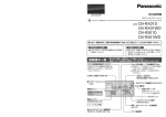
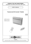
Communications and smart Motion control in one shield! 3.3V Power LED DTR TX RX NC NC GND FTDI 1 I²C Address Select 5V Power LED Reset Button Vin Isolation Jumper S Encoder 2 S Motor 2 M2 LED 3.3V 300mA 5V 1A +3.3V MCU1 DOUT DIN MCU Program Selection Switch + Positive S GND S MCU2 M4 LED Encoder 1 M1 LED S DTR TX RX NC NC GND M3 LED Xbee / WiFly TX and RX LEDs FTDI 2 - Negative Encoder 4 Motor 4 S Motor 1 6V - 16V DC Encoder 3 Motor 3 ISP Reset Jumper Introduction The ComMotion is an I²C controlled, 4 channel motor controller in an R3 shield format. The advantage of using I²C is that the shield only uses 2 pins. This leaves most of your pins free for use with other shields, sensors and circuits. The ComMotion shield can drive 4 DC brushed motors up to 2.5A continuous each with peak currents up to 4A per motor. Current monitoring is used to limit the maximum current for each motor. Each motor has an encoder input that can be used for precise speed control. Encoder feedback also gives the motor much more torque at low speeds. Preset configurations allow you to control robots with either omni or mecanum wheels by sending the ComMotion shield only 3 simple values: Velocity, Angle and Rotation. The two ATmega328P onboard processors will then do the trigonometry required to calculate the correct speed for each individual motor. If encoders are not being used then the shield will still function normally but motor speed control will be the same as with standard motor drivers. Speed control will be less accurate and the motors will have much less torque at low speeds. Each processor has it's own serial port broken out into an FTDI header. These serial ports can be used for GPS, Bluetooth and LCD modules while leaving your Arduino serial port free for uploading and debugging code. The serial port on MCU2 is also broken out into a socket for an XBEE or WiFly wireless transceiver with voltage translation circuitry and a dedicated 300mA, 3.3V regulator. Wireless Control The default configuration allows the ComMotion shield to accept serial commands directly from the serial port on MCU2. Just plug in a pre-configured Xbee, WiFly or Bluetooth module and you have instant wireless control. No Arduino required. Copyright C 2014 by DAGU Hi-tech Electronic Co., Ltd. All rights reserved. No portion of this instruction sheet or any artwork contained herein may be reproduced in any shape or form without the express written consent of DAGU Hi-tech Electronic Co., Ltd. The manufacturer and distributor cannot be held responsible for any damages occurred by mishandling, mounting mistakes or misuse due to non-respect of the instructions contained in this manual. Manufacturer: DAGU Hi-Tech Electronic Co.,LTD WWW.AREXX.COM.CN RS039 Contents Powering ComMotion 1 Out of the box 1 Using ComMotion for the first time 1 Controlling ComMotion - I²C data packs 2 Basic Configuration 2 Encoder Configuration 3 Controlling the motors 4 Using chassis configurations 4 Serial configuration 5 Sending serial data 5 Receiving serial data 5 Requesting shield status 6 Motor error log 6 Communications error log 6 Re-programming ComMotion 7 Specifications 8 The ComMotion PCB is a 4 layer, double sided PCB that packs a lot of features into one small shield. Powering ComMotion The ComMotion shield can draw as much as 10A of current with 4 motors running at 2.5A each so it is important to use good quality NiMh batteries or a Lithium battery pack, do not use Alkaline batteries. Arduino boards are not designed for such high currents so you should connect your battery pack or power supply straight to the ComMotion shield. With the Vin jumper shorted, The Arduino board will get power from the shield. As the ComMotion shield can work on a wider voltage range than most Arduino boards it may be necessary to power it from a separate power supply. Remove the Vin jumper to isolate The Arduino Vin from the ComMotion's power supply. You can then power the Arduino board and the ComMotion shield from separate battery packs or power supplies. Out of the box The ComMotion shield comes with demonstration software used in the Scamper robot kit. When you first turn it on it will play a tune if the demo mode is on or or beep a few times if it is off using all connected motors for speakers. If it has not received any data or commands from the I²C bus or a serial port by the time the tune is complete it will then run in demo mode. The demonstration program can be toggled on or off by pressing the reset button or cycling the power. Even if you are not using a Scamper robot this is a useful tool to determine if the board is functioning ok. Once the shield has received data or a command it will no longer default to demonstration mode unless you re-set the configuration to demonstration mode. The ComMotion shield comes pre-programmed to work as an I²C controlled, 4 channel, smart motor controller. The term smart refers to the fact that the controller will use encoder inputs to try and maintain steady motor speeds regardless of the motors load. This allows the motors to be driven at low speeds and maintain full torque without stalling. If you are not using encoders then this feature can be disabled in the configuration. The controller will then behave like a standard motor controller. Using ComMotion for the first time The first thing to do is determine which I²C address you want to use. Even if you plan to use serial control you should check to make sure the shields I²C addresses do not conflict with any other I²C devices you might be using as the two processors communicate with each other using the I²C bus. The ComMotion shield defaults to I²C addresses 30 and 31 with all dip switches off. If this conflicts with another device on the bus then use the table below to select a new address. Although there are 2 processors on the I²C bus you only need to communicate with MCU1. The address of MCU2 is only shown here to help prevent conflict with other devices. DECIMAL VALUE DIP SWITCH SETTING ADDRESS MCU1 MCU2 DECIMAL VALUE DIP SWITCH SETTING ADDRESS MCU1 MCU2 0 0 1 8 16 17 1 2 3 9 18 19 2 4 5 10 20 21 3 6 7 11 22 23 4 8 9 12 24 25 5 10 11 13 26 27 6 12 13 14 28 29 7 14 15 15 30 31 1 Controlling ComMotion All commands are sent to the ComMotion shield using either the I²C bus or a serial port. The commands are all sent as data packets. This is actually much simpler than it sounds and once the configuration packets are sent you will mostly use command 3 to control the motor speeds. The first byte of each data pack tells the shield what type of information is being sent. The rest of the pack is the information needed to complete that command. Bytes can only have a value from 0 to 255 but some information will be bigger numbers called Integers. Integers are 16 bit numbers and must be broken into bytes before we can send them. The easiest way is by using the Arduino IDE highByte() and lowByte() commands. Once the integers have been broken down into two bytes they can then be transmitted over the I²C bus or serial data stream. For example, to control the speed of each motor individually you first send the number 3 which indicates the pack is a command to control the motors. You then send the desired speed of each motor from -255 to +255. Even if you are not using 4 motors you still need to send 4 speed values. Just use 0 for any unused motors. There are only 6 commands needed for the ComMotion shield. 1. Controller Configuration 2. Encoder Configuration 3. Motor Control Set values such as low battery voltage, maximum motor current etc. Set values for motor RPM, encoder resolution, reserve power and stall time. Change the speed of the motors. 4. Serial Configuration 5. Send Serial Data 6. Shield Status Set baud rates for each port and select a command port for serial control. Sends data to a serial port. Returns information such as battery voltage, motor currents etc. Basic Configuration You will need to configure the ComMotion shield at least once to suit your application. This is done by sending a basic configuration data packet which consist of 9 bytes as listed below: Byte 1 2 3 4 5 6 7 8 9 10 Function 1=basic config. mode configuration low battery voltage max current M1 max current M2 max current M3 max current M4 I²C offset I²C master address Short Description Specifies that the data pack is basic configuration data. 0=I²C or Serial input 1=demo mode 0=3x Omni 1=4x Omni 2=Mecanum 3=individual +16=encoders off 60 = 6.0V use 60 for 2S LiPo use 90 for 3S LiPo batteries 255 = 2.55A 255 = 2.55A 255 = 2.55A 255 = 2.55A 0=no offset I²C address offset used to extend range of available I²C addresses 1=default value This is the address of the external I²C controller. Byte 1: Must always 1. This tells the shield that the data pack is basic configuration data. Byte 2: Demo mode is the default. Set to 0 if you want to control the shield by I²C or Serial commands. Byte 3: Select your chassis configuration or select individual motor control. Add 16 if you don't use encoders. Byte 4: Default value is 60 (6V). This value is the minimum battery voltage x10. Shutdown occurs below this voltage. Bytes 5-8: You can set a maximum motor current for each motor. The default is 255 which is equal to 2.55A. Byte 9: If necessary you can offset the I²C address by this amount to avoid conflicts. Default value is 0. Byte10: The ComMotion shield is an I²C multi-master device. If your using an external controller as an I²C master then it must be at this address to receive status reports and warnings. Default value is 1. 2 Encoder Configuration If you are not using encoders then you can ignore this command. As the ComMotion uses the time between encoder state changes to determine the actual speed of the motor it needs to know the motors maximum speed and the encoder resolution to determine what is the fasted speed. When you give the controller a desired speed from -255 to + 255 the controller then coverts this number into a percentage of the fastest speed. Byte 1 2 3 4 5 6 7 Function 2=encoder config. maximum RPM maximum RPM encoder res. x100 encoder res. x100 reserve power % max stall time in mS Short Description Specifies that the data pack is encoder configuration data Motor RPM at the motors rated voltage (high byte) Motor RPM at the motors rated voltage ( low byte) 800=8 state changes per motor revolution (high byte) 800=8 state changes per motor revolution ( low byte) 50=50% 1-255mS. A value of 0 is invalid and will automatically be changed to a 1. Byte 1: Must always be 2. This tells the shield that the data pack is encoder configuration data. Byte 2&3: This is the maximum speed of the motors under load at the rated voltage. Byte 4&5: This is the encoder resolution x100. For example 225=2¼ state changes per motor revolution. Not to be confused with encoder resolution per wheel revolution which depends on the gearbox ratio. Byte 6: Reserve power as a percentage from 0% - 50%. Default is 10%. Byte 7: Default is 10mS but some experimentation will be required depending on the application. The default encoder configuration is set for a motor with a maximum speed of 13,500 RPM and an encoder with a resolution of 8 state chenges per motor revolution. This suits the Scamper robot kit however for a Rover 5 chassis the speed should be set to 8,500 RPM and the encoder resolution set to 2 state changes per revolution. Incorrect values will either prevent the motors from reaching their maximum speed or else acheiving their maximum speed at less than 100%. To ensure that the motors can acheive the desired speed it is recommended to keep some power in reserve to allow for changing loads. This ensures that even at full speed the robot can still travel in a straight line or the desired angle. If the reserve is too small then the motors speeds will loose accuracy at high speeds under load. If the reserve is too low then the robot will not move as fast as possible. Typically 10-15% should be enough but it will depend on the weight of the robot, friction in the wheels and the terrain. Some experimentation may be required. The maximum stall time is used by the controller to determine if the motor is just running very slow or has actually stalled. Larger values may make slower speeds possible but will also slow the controllers response time. Low resolution encoders will need longer stall times. Some experimentation will be required. For the Scamper robot kit which has 13,500 RPM motors and an encoder resolution of 8 state changes per motor revolution a maximum stall time of 10-15mS works well. For the Rover 5 robot chassis which has 8,500 RPM motors and an encoder resolution of 2 state changes per revolution (using only 1 of the 2 encoder outputs) a maximum stall time of 25-50mS works better. DAGU kits use an 8 pole magnet and hall effect sensors however the ComMotion shield will work with any encoder that generates a digital output. High resolutions are required for a good range of speed control. Rover 5 encoder Scamper encoders 3 Controlling the Motors Once the shield has been configured we can control the motors with a Motor Control data packet. This is the data packet you will use the most. If you set the chassis configuration to 3x Omni wheels, 4x Omni wheels or Mecanum wheels then the controller will automatically do the trigonometry required to calculate the individual motor speeds. This allows you to control a robot chassis with just 3 integers. Velocity: Angle: Rotation: The desired speed from -255 to +255. Positive values are forward, negative values are reverse. 0° is forward, 90º is to the right, 180° is backward, 270° is left. Negative values reverse angle. Values from -255 to +255. Positive values rotate clockwise. If you set the configuration for Individual motor control then you only need to send 4 numbers, the speed of each motor from -255 to +255. Positive values run the motor forwards and negative values run the motor in reverse. Byte Function Description 1 3=motor control Specifies that the data pack is motor control data 2 3 4 5 6 7 8 9 Omni and mecanum wheels velocity high byte velocity low byte angle high byte angle low byte rotation high byte rotation low byte not required - ignored not required - ignored Individual motor control M1 speed high byte M1 speed low byte M2 speed high byte M2 speed low byte M3 speed high byte M3 speed low byte M4 speed high byte M4 speed low byte Byte 1: must always be 3. This tells the shield that data pack is motor control data. As integers are 16 bit numbers they must be broken into bytes using the Arduino IDE highByte() and lowByte() commands.They can then be transmitted over the I²C bus or serial data stream. Using chassis configurations The ComMotion shield has 3 configurations programmed into it. When one of these configurations is selected then the shield will calculate the speed and direction of each motor for you based on three integers, velocity, angle and rotation. When using any of these 3 pre-programmed configurations, the motors are always numbered in a clockwise direction as shown in the diagrams on the right. Match the motor numbers with the motor outputs on the shield. 120° M3 120° M1 120° M2 No matter which configuration you choose, test that the wiring is correct by trying to rotate. If a motor spins in the wrong direction then swap it's wires around at the screw terminals. If you are using mecanum wheels then make sure they are orientated the same way as shown in the diagram. Offsetting omni wheels You will notice in the diagrams that the omni wheels on the triangular chassis are centered but on the square chassis the wheels are off-center. M4 M3 M1 M2 This is because with omni wheels it does not matter if they are centered or not. Only the angles matter. Sometimes offsetting your wheels allows you to make a smaller chassis because it allows more efficient spacing of the motors. Other configurations If your chassis does not match one of these configurations then configure the shield for individual motor control. Your software can then control the motors in a way that suits your chassis. 4 M4 M1 M3 M2 Serial Configuration This data pack allows you to set the baud rate for the serial ports on MCU1 and MCU2 and specify if the ComMotion shield should accept commands directly from a serial port or simply pass the data to the I²C master for processing. The default baud rate for each serial port is 9600. For the rest of this manual, port 1 refers to the serial port on MCU1 and port 2 refers to the serial port on MCU2. Byte Function Description 1 2 3 4 5 4=serial configuration buad rate high byte baud rate low byte buad rate high byte baud rate low byte specifies that data pack is serial configuration data set the baud rate for port 1. set the baud rate for port 1. set the baud rate for port 2. set the baud rate for port 2. 6 serial mode (default 4) 0=pass all serial data to I²C master for processing. 1=accept control data packs from port 1 - pass all data to I²C master for processing. 2=accept control data packs from port 2 - pass all data to I²C master for processing. 3=accept control data packs from port 1 - pass all data back to port 1. 4=accept control data packs from port 2 - pass all data back to port 2. In modes 0,1 and2, data from serial ports 1 and 2 will be sent to the I²C bus. To indicate where the data came from each serial data pack will start with an ID header #SP1 or #SP2. The ComMotion shield will accept commands from the serial port on MCU2 and send back all data to the serial port on MCU2 by default (mode 4). This means that if you install a Bluetooth, Xbee or WiFly module then the ComMotion shield can be controlled wirelessly without an Arduino or any other external processor and all serial data received from the serial port on MCU1 can be sent back through the serial port on MCU2. In the example below, a pre-configured Xbee module is plugged into the ComMotion shield and a GPS module is connected to port 1. All data received from the GPS module will automatically be transmitted back through the Xbee module on port 2. GPS module Xbee module MCU1 Serial port MCU2 Serial port Send Serial Data This data pack is used to send data to a serial port. The maximum data limit per pack is 30 bytes due to the I²C buffer. If you need to send more than 30 bytes of serial data then you must send multiple serial data packs. To prevent buffer overflows when sending multiple data packs it may be necessary to limit data pack size and send more, smaller packs. This will slow the transmission rate slightly allowing the buffer to clear between packs. Byte Function Description 0 1 5=serial data select serial port specifies that the data pack is serial data 0=previous 1=MCU1 port 2=MCU2 port 2-31 serial data of any length up to 30 bytes Byte 0: must always be 5 to tell the ComMotion shield that you want to send serial data. Byte 1: selects which serial port to send the data to. The rest of the data pack is the data to be sent. Receiving Serial Data As mentioned in Serial Configuration, all serial data received from either serial port will be directed as determined by the serial mode. If for example the ComMotion shield has a serial LCD display on serial port 1 and a GPS module on serial port 2 then set the mode to 0. The Arduino will then receive all data from the GPS module through the I²C bus and can then display the data by sending it to port 1. 5 Requesting Shield Status The ComMotion shield can give you information you may find useful in your programs. By requesting status data from the shield you can read the battery voltage and how much current each motor is drawing. You can read analog sensors connected to the spare analog inputs. If you use encoders then you can read the counts of each encoder to measure distance. You can even request error information from the shield such as which motors had stalled. Byte Function Description 1 2 6=Status request data required Specifies that the data pack is a status request Each bit is a seperate request allowing any combination of status information. Byte 1: must always be 6. This tells the shield that the data pack is a status request Byte 2: each bit is a different request as listed below. You can request any combination of status reports. The status reports will be sent in order from bit 0 to bit 7. For example, if bits 3 & 4 are high (8+16) then 6 bytes will be returned for the analog inputs on MCU1 followed by 6 bytes which are the analog inputs from MCU2. Bit 0: Bit 1: Bit 2: Bit 3: Bit 4: Bit 5: Bit 6: Bit 7: Returns 8 bytes, the encoder count from each motor high byte first. Resets all encoder counters. If bit 0 is high then the counters will be read before being reset. Returns 8 bytes, the current draw of each motor high byte first. Returns 6 bytes, the analog inputs A3, A6 and A7 from MCU1, high byte first. A7 is battery voltage. † Returns 6 bytes, the analog inputs A3, A6 and A7 from MCU2, high byte first. Returns 1 byte, the error log for the motors. Returns 1 byte, the error log for communications. Clears the error logs. If bit 5 or 6 are high then those error logs will be read first. † Battery voltage = MCU1analog input A7 * 30 / 185. A result of 84 = 8.4V Motor Error Log When you request the motor error log you will receive a single byte. A value of 0 indicates no errors. Each bit indicates a different error. Bit 0: Bit 1: Bit 2: Bit 3: Bit 4: Bit 5: Bit 6: Bit 7: A high value indicates that motor 1 is drawing the maximum current as set in the shield configuration data. A high value indicates that motor 2 is drawing the maximum current as set in the shield configuration data. A high value indicates that motor 3 is drawing the maximum current as set in the shield configuration data. A high value indicates that motor 4 is drawing the maximum current as set in the shield configuration data. A high value indicates that motor 1 drew excessive current and caused a shutdown to occur. A high value indicates that motor 2 drew excessive current and caused a shutdown to occur. A high value indicates that motor 3 drew excessive current and caused a shutdown to occur. A high value indicates that motor 4 drew excessive current and caused a shutdown to occur. Normally if the current draw of a motor reaches the limit set in the configuration data then the PWM value to that motor will be reduced to limit the current to the maximum value. If the motor current exceeds a safe level for the shield then the shield will shutdown in an attempt to prevent damage. In the event of a short circuit, some batteries can deliver very high currents and the shield may not be able to shutdown quick enough. If you are using Lithium batteries then a 2.5A, fast blow fuse should be wired in series with each motor as an added level of protection against short circuits. Communications Error Log When you request the communications error log you will receive a single byte. A value of 0 indicates no errors. Each bit indicates a different error. Bit 0: Bit 1: Bit 2: Bit 3: Bit 4: Bit 5: Bit 6: Bit 7: A high value indicates an I²C buffer overflow. A high value indicates serial port 1 buffer overflowed. A high value indicates serial port 2 buffer overflowed. reserved for future software updates. reserved for future software updates. reserved for future software updates. reserved for future software updates. reserved for future software updates. 6 Re-programming ComMotion On rare occasions the flash memory can get corrupted during a brown out. If this does happen then the ComMotion code can be easily restored using the ArduinoISP example code that is included with the Arduino IDE. Install the ArduinoISP example code into an Arduino board and then plug in the ComMotion shield. In the Tools menu, set the board type as UNO and select "Arduino as ISP" as your programmer. Short the jumper RST on the ComMotion shield. This will connect D10 of the Arduino board to the ComMotion shields reset circuit. Now use the MCU selection switch to select which processor to reprogram. Load the ComMotion code and use the "Upload Using Programmer" option to upload the code. MCU selection switch RST ISP header SparkFun RedBoard with ArduinoISP example code installed The same code should be uploaded to both processors so upload to MCU1 first and then again to MCU2. Once the code has been uploaded to both processors then put the switch to the center position to isolate the ISP header and open the jumper RST. In extreme cases the fuses may also need to be reset. This is done by burning the bootloader to each processor first.The bootloader will be overwritten when we upload the code but this is the easiest way to ensure the fuse settings are correct. Once the bootloader has been loaded into both processors, upload the code again. Modifying the code Only experienced programmers should attempt to modify the code. If you intend to modify the code then you should understand that the code is time sensitive. You cannot use functions such as delay() or delayMicroseconds() as this will prevent the motor speed control code from working correctly. You should make sure your code works on both processors using the variable "byte mcu;" to determine which mcu it is running on. Use the program tab [IOpins.h] as your wiring diagram. 7 ComMotion Specifications Processors: Supply voltage: Logic voltage: 2x ATmega328P (16MHz) 6V – 16V 5V @ 1000mA* Wireless support: Xbee / WiFly power: Xbee / WiFly socket with voltage translation 3.3V @ 300mA Battery monitor range: Battery monitor resolution: Analog Inputs: 0V – 17V ≈0.02V 5x 10bit (A3,A6 MCU1 – A3,A6,A7 MCU2) Motor drivers: Motor current continuous: Motor current stall: Current monitor range: Current monitor resolution: 4x FET “H” bridge 2.5A 4A 0A – 5A ≈5mA (each motor) (each motor) (each motor) (each motor) I²C bus voltage: I²C bus speed: I²C addresses: Serial ports: 5V or 3.3V 100 kbit/s 16 selectable pairs 2x 5V TTL logic (selected by IO_REF pin) (software configurable) (FTDI headers) *Current limit for 5V regulator is dependant on supply voltage and ambient temperature. The current ratings below assume an ambient temperature of 25°C. 1A @ 6V 580mA @ 8.4V 285mA @ 12V 8 180mA @16V