1
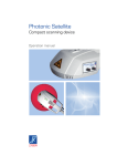
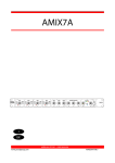
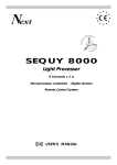
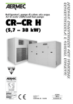
LibreCad
User manual (version 2.0.0 beta 1)
LibreCad User manual – page 1
GENERAL BARS
THE FILE BAR
This bar is the basic bar that you may find in any other applications, is quite standard,
looking at the picture under the title there are in order :
• New file;
• Open a file;
• Save file;
• Print draw;
• Print preview. (*)
(Please notice that LibreCad operates with .DXF file format)
THE EDIT BAR
This is another common bar that many other programs have, there is nothing specific
considering the “cad side”, the icons' function are in order:
• Switch to selection
pointer;
• Undo the last
operation;
• Redo the last
operation;
• Cut;
• Copy;
• Past.
THE VIEW BAR
This bar is a bit more specific; it allows to:
•
•
•
•
•
•
•
•
•
Show the grid;
Turn on/off the draft mode;
Redraw the work;
Zoom in;
Zoom out;
Auto zoom;
Previous view;
Zoom a selected window;
Activate the pan.
LibreCad User manual – page 2
COORDINATES
Before to start with the cad commands, it is really important to have clear the meaning
of the word “coordinate”. If you are already into others cad system probably this little
chapter is not necessary to be read.
A Cartesian coordinate system it is a system that specifies each point uniquely in a plane
by a pair of numerical coordinates (1), which are the signed distances from the point to
two fixed orthogonal directed lines, measured in the same unit of length. Each reference
line is called a coordinate axis or just axis of the system, and the point where they meet
is its origin, usually at ordered pair (0,0). The coordinates can also be defined as the
positions of the perpendicular projections of the point onto the two axes, expressed as
signed distances from the origin, the picture explains those concepts.
1
In LibreCad Cartesian coordinates can be inserted considering two cases, that may give
the same result:
1. Absolute coordinates (the origin lays on the coordinates 0,0)
2. Relative coordinates (the origin does not lay in coordinates 0,0)
To simplify those concepts, let's suppose that want to locate the green point in figure 1.
1. The distance of the green point from origin is 2 on the X axis is and 3 on the Y axis, so
to draw a line from the violet point (that lays on the origin) to the green point we need
to consider the coordinates of the violet point 0,0 and the green point is 2,3.
The coordinates are: first point (violet) 0,0 – second point (green) 2,3.
2. In this case the origin does not lays on 0,0 but in another point. We pretend the origin
switch to the blue point. Now the distance between the blue point and the green point
is given by the algebraic differences between the coordinates of the green point and the
coordinates of the blue point, so the distance is 3.5,5.5. In case1 too is used this method,
but the operation results simplier because the numbers 0 simplify the operation.
Then to draw a line from this new origin to the green point, the first coordinates are 0,0
and the second coordinates are 3.5,5.5.
Now, if want to draw a line from the violet point to the green point, we need to enter
other coordinates of the violet point, because now it does not lays on the origin, the
origin is -1,5,-2,5, so the difference between the violet and blue point is 1.5,2.5.
Finally, to draw a line from violet point to the green point having the origin is blue point,
the coordinates are: first point (violet) 1.5,2.5 – second point (green) 3.5,5.5
LibreCad User manual – page 3
CAD BARS
LAYERS
Layers are useful to visualize only certain entities, or put together entities with similar
proprieties, depending on preferences, needs, kind of work planning.
As shown in the picture there is the layer 0 always present as default.
More in detail this section:
this icon shows all the layers in the work and
this icon hides them all;
this icon add a layer;
this icon remove a layer;
with this icon is possible to set the layer's name, color, width, and line type.
Considering the list here below there are other proprieties
This show/removes
the relative layer
Layer search
This freeze
the relative layer
Active layer
This print or not
the entities relative
to the layer
LibreCad User manual – page 4
Moreover, clicking with right mouse button, you can select if defreeze or freeze layer,
add or remove a layer, edit a layer or toggle its visualisation.
Examining the menu below:
it allows to draw entities with different features from the others of the same layer,
select color, width, line type; all this before creating entities, after set new preferences
the further entities will have the new features. (e.g. if layer 0 has white color and then
the color selected is yellow, from the changings selected all entities will be yellow, not
white).
THE SNAP SELECTION BAR
This is the very first cad bar, when entities (line, circle, etc) are drawn, this bar allows to
bind the first point of the entity and the following others, in order of the picture above
respectively:
• free;
• to an end point;
• to a point on an entity;
• to centre point;
• to the middle point; – look tool options bar –
• to a distance from an entity;
• to an intersection point;
• horizontally
• vertically
The last two icons set the relative zero and lock its position.
THE TOOL OPTIONS BAR
This bar is mainly empty, but selecting some particular tool, for example the snap middle
from the snap bar, or the print preview, tool options bar bar will change like shown
below:
This option increase or
decrease the number
of middle points
This option allows the user
to assign a scale to the print;
selecting “fixed” will
freeze the scale inserted
Those three icons:
-toggle black/white mode
-center draw on paper
-fit the draw on paper
In this case notice that clicking on the icon ”fit on paper” will automatically assign a scale
in the print. See further chapter PRINT. Sometimes selecting an icon may seem to have
not enough options, so attention on the icons in this manual related to this bar.
LibreCad User manual – page 5
THE CAD TOOLS BAR
This is the bar that allow to create entities, modify them, dimension them, create blocks
and select entities. In LibreCad is very simple create and modify entities; it is enough
click on relative icon (lines, circles, ellypses, polilines, splnes) click the relative icon in the
sub-menu that may appear and give the imput desired. To enter a text is enough to click
on the relative icon and set the attributes of the tex at the left of the editor and enter
the text in the right, in the very editor.
LINES
This is one of the most used command among all the commands. Depending on the
SNAP BAR, that allows to bind entities to snaps (bind lines in this case), clicking on this
icon will show a new sub-menu that allows to draw lines
A line by two points
A line by a given angle
A horizontal line
A vertical line
A rectangle
A bisector
Parallels with distance
Parallels through points
Tangents from points to circles
Tangents from circle to circle
Tangents to circles
orthogonal to lines
Orthogonal lines
Polygons with center and corner
Lines with relative angles
Free hand lines
Polygons with two corners
– look tool options bar –
The way to draw lines, in each of the option in the sub-menu, is quite simple: first click on
the first point, snap, or entity, then click on the second point, snap, or entity and a line
LibreCad User manual – page 6
will be displayed on the screen. To create vertical lines, horizontal lines or lines with a
given angle after selecting the icon, a feature menu will appear in tool options bar, and
here length, angles are set.
1
2
In the example instead, there is a line between two points. Select a point (1) and another
point (1) and a line will be created. Notice that the command “line” is not deactivated,
so, each further click will generate a line from the last point of the previous line to the
point where the mouse has been clicked the last time (2). In this case notice also that the
grid is show and the grid snap is active. This result is possible even by giving the line
coordinates from the command line. To give relatives coordinates, before coordinate
values, the symbol @ that switch the origin.
ARCS
To create an arc simply click on the relative icon, even in this case a sub menu will
appear, and for each icon will be drawn an arc with special features. This command is
similar to command “line”.
By point and angle
By trhee points
Tangential to base
entity with radius
Concentric
Here an example:
1
2
To create an arc with three points on this figure click on the arc icon, then click on the
relative sub-menu icon, then on the endpoints (1) and the figure 2 is the result. Notice
LibreCad User manual – page 7
that to have a precise arc on specific points, the snap endpoint must be activated.
CIRCLES
Circles are created clicking on the relative icon, and when this icon is clicked a sub menu
will appear, this menu allows to create circles
With center and a specific point
With center and a radius
With 2 opposite points
Passing through three points
Concentric
Inscribed in a triangle/polyline
with 3 lines
Tangent to other 2 circles
with radius given
Tangent to other 2 circles
passing through a given point
Tangent to a circle passing
two given points
Tangent to other 3 circles
In the example down here, is shown a circle inscribed in a polyline:
1
2
The polyline (1) is the shape tangent to the circle that has to be created, to obtain the
circle, simply click on the relative icon, select the three lines and the result is a circle
inscribed in the polyline (2).
ELLYPSES
The command “ellypses” is very similar to the command “circle”, so it will be shown the
sub menu, to list the options of this command to create ellypses
With center,2 points and angle
With center and 2 points
By 4 points on ellypse
By foci and point on ellypse
Inscribed in a quadrilateral
or tangent to 4 lines
By center and 3 points on ellypse
LibreCad User manual – page 8
POLYLINES
??????????????
SPLINES
This icon allows to create splines: once the command is selected, is just enough to click
the location needed to locate the points of the desired spline. Here an example (1)
1
HATCHES
In order to fill a border (1) with a hatch, the shortest way is to select the entire contour
that needs to be filled with the hatch (2), then click on the relative icon then give
confirm, finally choose the hatch and the scale and the hatch will be created (3) . In
alternative it is possible have hatches by clicking the relative icon, click the relative icon
on the select/deselect/invert selection/etc hatches sub-menu, depending on the need,
and give confirm, then select the hatch and the scale. Scale and angle obviously will not
work on solid fill. In the example above there is a“concrete” hatch, scale 1.5 angle 0
1
2
LibreCad User manual – page 9
3
LibreCad User manual – page 10