1
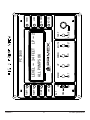
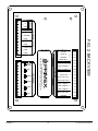
PC-3000
PUMP CONTROLLER
User Manual
WWW.PRIMEXCONTROLS.COM
Ashland, OH
800-363-5842
Clearwater, FL
800-349-1905
Detroit Lakes, MN
888-342-5753
Milford, OH
513-831-9959
PN 1038551A
© 2013 SJE-Rhombus® Rev 09/13
PRIMEX is a trademark of SJE-Rhombus®
PC3000
Table of Contents
1.0 INTRODUCTION ............................................................................................. .............. 3
2.0 OPERATION 4 ............................................................................................................... 3
2.1 PUMP DOWN OPERATION............................................... .......... ....................... 3
2.1.1 SINGLE FLOAT BACKUP ................................................... .......... ....................4
2.1.2 PUMP SEQUENCE TIMERS .................................................................... ........ 4
2.1.3 TIME AT SETPOINT .......................................................................................... 4
2.1.4 FAIL TO START TEST ....................................................................................... 5
2.2 PUMP UP OPERATION .............................................................................. ......... 5
2.3 ALTERNATION ......................................................................................... ............ 5
2.4 STARTUP ................................................................................................ ............. 6
2.5 FRONT PANEL INDICATORS AND CONTROLS ............................................. ... 6
2.6 SETPOINT MENU ................................................................................................ 8
2.7 CONFIGURATION MENU .................................................................................... 8
3.0 SPECIFICATIONS ................................................................................. ............... .......11
3.1 INPUT SIGNALS ................................................................................. ........... ....11
3.2 OUTPUT SIGNALS ................................................................................. .......... .12
4.0 CONNECTOR PINS ..................................................................................... ............. ..13
FIGURE 1 FRONT VIEW ..................................................................................... ............ .15
FIGURE 2 BACK VIEW ............................................................................. ............. ...........16
FIGURE 3 MOUNTING DIMENSIONS ................................................................ ..............17
FIGURE 4 EXAMPLE WIRING ............................................................................. .............18
QUICK SET UP CHART ................................................................. ........ .............APPENDIX
PRIMEX™
2
PC-3000 Specifications
PC3000
1.0 INTRODUCTION
The PC-3000 is a general purpose pump controller designed to control up to 3 pumps,
in either pump up or pump down applications. It sequences pumps on and off in response
to changes in level, pressure, or flow. The primary sensor input is a 4 to 20 mA. current
loop which can be connected to any sensor which has a 4-20 mA. output. When used to
control level in a tank or well the input is usually connected to a pressure transducer,
or ultrasonic transmitter. A loop power supply is provided in the PC-3000.
The PC-3000 can be configured for many applications using it’s easy-to-use front panel
user interface. Wiring is easy using removable terminal blocks on the back cover. Field
replacement is easy because the terminal blocks unplug from the controller so no wires
need to be disconnected.
FEATURES
• 32 character alpha-numeric liquid crystal display for level, status, and setpoint information.
• Alternation selection switch on front panel to turn alternation on and select the lead
pump if alternation is off.
• Simple menu structure for easy display and modification of setpoints and setup configuration.
• Built in elapsed time meters for all pumps. They are nonvolatile and easily examined
from the front panel.
• 4 to 20 mA main sensor input with loop power supply for easy connection to most
transducers and transmitters. Adjustments are provided for both scale and offset.
• Inputs for pump seal leak sensors and pump over temperature sensors with display
messages for out of specification conditions.
• Fully scaleable 4-20 mA level output transmitter.
• Built in single float backup system for pump down applications.
• Three auxiliary inputs which can be pump disable or pump run confirmation inputs for
a fail to start test.
• Built in horn relay with internal and input for external mute button.
• Relay outputs for both high and low level alarms with adjustable setpoints.
• Individually selectable on and off setpoints for up to three pumps.
• All inputs are filtered and transient protected.
• Built in software, no programming required.
• All inputs operate on low voltage and current.
• Input power is 115 V AC, internally fused and transient protected.
• All terminal strips unplug without removing the wires for easy field replacement.
2.0 OPERATION
2.1 Pump Down Operation
Pump down is used in applications , like wastewater lift stations, where a liquid flows
into a tank or well and must be pumped out. As liquid flows in the level in the well rises.
The level is continually monitored by the level transmitter which sends a 4-20 mA signal
to the controller which displays the level on the first line of the display. If the level is
below the low alarm setpoint then the low alarm light and relay are activated. If the horn
is enabled then it too will be activated. As the level rises above the low alarm setpoint
the low alarm condition will be cleared. When the level rises above the lead pump on.
PRIMEX™
3
PC-3000 Specifications
setpoint the lead pump will be called to run. Which pump is the lead pump is determined
by the alternator. The current lead pump is displayed on the right side of the top line
of the display. When the lead pump starts the liquid level should begin to fall as liquid
is pumped out of the well. When the level falls to the lead pump off setpoint then the
lead pump will be stopped and the alternator sequenced if it is on. If the level continues
to rise it will reach the lag pump on setpoint and the lag pump will be called. If the level
then falls to the lag pump off setpoint then the lag pump will be turned off. The lag pump
will not be called if the total number of pumps setting is 1. If the lead and lag pump
running do not cause the level to fall then the third pump will be called when
the level reaches the lag2 on setpoint and if three pumps are selected for the maximum
number of pumps. If the level continues to rise then it will reach the high alarm setpoint
and set a high alarm condition. The high alarm light and relay will be activated. If the
horn is enabled then it too will be activated until the alarm condition clears or until the
mute button is depressed.
2.1.1 Single Float Backup
A single float backup system is provided in pump down mode only. It can be useful if
the primary level sensor fails. A single normally open float switch is connected to the
float input and suspended in the well at a point above the normal operating levels of the
system. In this way the float will only be submerged if level rises above that required
to call on all available pumps. The backup system is enabled by setting a backup time (
in seconds ) in the backup time setpoint of the configuration menu. If this time is zero
then the backup system is disabled. If the high float is activated, and backup is enabled,
and the controller is not already calling for all available pumps then the backup mode is
initiated. The float light on the front panel is turned on and the lead pump is called to
run. At the same time two timers are started, one for 30 sec. and one for 60 sec. If
the high float opens ( comes out of the liquid ) then these two timers are cleared and
no further pumps will be called. The lead pump will remain on for the period of time set
in the backup time setpoint. If the 30 second timer expires before the high float opens
then the lag pump will be called if there are at least 2 pumps. If the 60 second timer
expires before the high float opens then the second lag pump will be called if there are
three pumps. All pumps will be sequentially turned off after the high float has been open
for a period of time equal to the backup timer setpoint. The float light on the front panel
will remain on until cleared by the reset/mute button on the panel or the external reset/
mute button.
2.1.2 Pump Sequence Timers
In both pump up and pump down modes there are two timers which prevent more than
one pump from turning on or off at the same time. These timers prevent excess power
loads when pumps are turning on and some hydraulic problems ( water hammer ) when
pumps are being turned off.
2.1.3 Time At Setpoint
The PC-3000 has a feature which prevents any pumps from being turned on or off until
a setpoint condition has been satisfied for a minimum time. This minimum time is the
TIME AT SP setting in the setup menu and can be set from 0 to 31 seconds. As an
example, assume this setting is set for 8 seconds, and we have a pump down system
(lift station). Then, the water level in the tank must exceed the lead on setpoint
continuously for 8 second before the lead pump will be called. There is not much need
for this in most lift stations as the level changes slowly but this feature can be very
PRIMEX™
4
PC-3000 Specifications
useful in water pressure (pump up) systems where the pressure may swing wildly for
several seconds after a pump is turned off or on. If this time is set longer than the
pressure takes to settle then no further pump calls will happen until the new pressure
has stabilized.
2.1.4 Fail to Start Test
The PC-3000 has an optional fail to start test. This optional test is controlled by the
START TEST time in the setup menu. If this time is zero then this test is disabled. If
the start test is enabled then the AUX/DIS inputs for each pump must be connected
through a dry contact to ground. These contacts must close and short the AUX/DIS
input to ground when the pump is running. The auxiliary contact on the starter or a
switch on the check valve arm can be used. If the start test is disabled ( time=0 ) then
these inputs are pump disable inputs. For example lets assume that the test is enabled
with a START TEST time of 15 seconds. When a pump is called a timer is started for
that pump. If the timer reaches 15 seconds and the AUX/DIS input for that pump has
not been shorted to ground then a fail to start test failure is set for that pump. The
pump is then disabled and the next available pump is called in its place. This failure condition
is displayed on the front panel and will remain active until reset by either a reset
button or reset input. The high level alarm will also reset this condition. This is to make
sure that a broken or misadjusted check valve switch does not cause an overflow.
2.2 Pump Up Operation
Pump up mode is used in situations, like water distribution, where the pumps must
maintain a pressure or fill a tank ( like a water tower ). For the purposes of this description
assume we have three pumps which will be used to maintain the level in a water
tank. The level is sensed by pressure transmitter mounted in base of the tank and all
three pumps send water to the tank.
As water is dispensed from the tank the level drops. If the level drops far enough to
reach the lead on setpoint then the lead pump is called to run. This should cause the
level to rise until the lead off setpoint is reached and the pump is shut down. If the
alternator is on then the lead pump will be sequenced to the next available pump. If the
level continues to fall then the lag on setpoint will be reached and the lag pump will be
called. As in pump down operation each pump has separate on and off setpoints and
there are setpoints for high and low alarm. Unlike pump down the pump up mode does
not have a float backup system.
2.3 Alternation
The PC-3000 has an automatic alternation system which can be used to cause a different
pump to be used each pump cycle. This is useful to equalize pump wear. When
the alternator is off the lead pump can be selected and that pump will always be called
first. The alternator on the PC-3000 is controlled by a toggle switch on the front panel.
When the switch is in the up position the alternator is on and the lead pump will be
changed each cycle. When the switch handle is in the center position the alternator is
off and the lead pump is selected by pushing the handle down. The handle has a spring
return from the down position. Each time the handle is pushed down the lead pump will
be incremented to the next available pump. The current lead pump is displayed on the
right side of the first line of the display ( LP=2 ).
PRIMEX™
5
PC-3000 Specifications
For systems with two pumps, alternation ( if on ) simply swaps lead pump duty between
the two pump each pump cycle. If there are three pumps, alternation can be either of
two options: In normal alternation, each pump cycle the next available pump is selected
as lead so that if all pumps are available then each will be lead every third time. The
other option is jockey pump. In this type of system pump 1 is a small pump and pumps
2 and 3 are large. The small pump (pump 1) is always the lead pump and the other two
pump alternate as lag and lag2. When either of the two large pumps are on the small
one is turned off. This is useful in systems where demand can be low at some times
and large at others.
2.4 Startup
When the PC-3000 is first powered up it executes an internal self test. During this
test many internal functions are checked and the displays are sequenced. The system
is controlled by an internal microcomputer which is monitored by a watchdog timer
system which will restart the system in the unlikely event that the program fails to
execute properly. After the self test is complete several timers are started which prevent
any relay outputs from activating until all of the system inputs have had a chance
to settle and all of the input filtering has resolved to their proper values.
2.5 Front Panel Indicators and Controls
Figure 1 is a view of the front panel of the PC-3000. It includes eight LED lamps, a 32
character LCD display, 5 push buttons, one toggle switch and one adjustment knob.
They have the following functions.
1. PUMP 1 THRU PUMP 3 LAMPS
These three green LED lamps indicate which pump is currently being called.
2. OFF LAMP
This green lamp indicates that no pumps are currently called to run.
3. HIGH LAMP
This red lamp signals that the level is above the high setpoint.
4. LOW LAMP
This red lamp signals that the level is below the low setpoint.
5. FLOATS LAMP
This red lamp will be on if the system has had a float backup cycle since the last reset
or power up.
6. XDUCER LAMP
This red lamp signals that the main level sensor input is outside of its normal range of
4 to 20 milliamps. This is useful for detecting transducer failures.
7. ALT SWITCH
The alternate switch will turn alternation on when up and off when in the center position.
When it is pushed down the lead pump will be sequenced to the next available
pump. The current lead pump is indicated on the first line of the display.
8. MENU BUTTON
This button is depressed and held for 10 seconds to enter the setpoint menu.
PRIMEX™
6
PC-3000 Specifications
9. UP / YES BUTTON
This button has several functions depending on the mode of the controller.
When the controller is in normal mode (not in one of the menus) this button causes
the bottom line of the display to sequence between pump status and the three elapsed
time meters. After 15 seconds the bottom line of the display always reverts to pump
status in normal mode.
When the controller is in one of the two menus this button is used to increment the
current parameter being adjusted or to tell the system to save the new value.
10. DN / NO BUTTON
This button has several functions depending on the mode of the controller.
When the controller is in normal mode (not in one of the menus) this button caused the
bottom line of the display to sequence between the pump status and the three elapsed
time meters.
When the controller is in one of the two menus this button is used to decrement the
current parameter being adjusted or to tell the system not to save the new value.
11. MUTE / RESET BUTTON
This button will reset any current latched up alarms such as temp fail or backup float. It
will also silence the horn if an alarm is currently active.
12. TEST / ADJUST BUTTON AND KNOB
The function of these two operators depends on the mode of the controller.
When the controller is in the normal ( not menus ) mode these operators are used to
test the system. When the TEST button is depressed and held the ADJUST knob will
be the level for the system. As you turn the knob up and down the level will go up and
down. This will call on pumps and make alarms just as if the level was coming from the
transducer. The controller will switch back to the transducer 8 seconds after the button
is released.
When the controller is in one of the menus these operators are used to change the
value of the setpoint or parameter. Depressing and holding the ADJUST button will
cause the knob value to be placed in the current parameter or setpoint. This can be
used along with the up and down buttons to easily adjust all of the setpoints.
13. 32 CHARACTER DISPLAY
This alpha-numeric display has two lines of 16 characters each. The first line always
displays the current level in feet and the current lead pump. The second line depends
on the mode of the controller.
In normal mode this line displays pump status or the elapsed time meters. Pressing
the up or down buttons will sequence through the three elapsed time meters. After
15 seconds this line will revert to pump status. When pump status is displayed the
display will read ALL PUMPS OK if there are no pump faults. If there are pump faults,
such as temperature failures or seal failures, they will be displayed one at a time every
2 seconds.
In either of the two menus the second line of the display shows the parameter being
adjusted and its current value.
PRIMEX™
7
PC-3000 Specifications
2.6 Setpoint Menu
The setpoint menu is used to examine and change the on and off setpoints for the
pumps and the high and low alarm setpoints. The menu is entered and updated using
the following procedure:
1. Depress the MENU button and hold it until the first setpoint appears on the bottom
line of the display. This will take about 10 seconds.
2. The display should say LEAD ON = XX.X FT. where XX.X is the current value for the
lead pump on setpoint.
3. If you wish to change this value then use the UP or DOWN buttons or you can hold
the ADJUST button down and turn the ADJUST knob until the value is correct. After
the value is correct then depress the MENU/NEXT button to go to the next setpoint.
4. If you have changed the value then the displays will ask SAVE? (Y/N) If you wish to
save the new value then press UP/YES if not then press DOWN/NO. The display should
change to the next setpoint.
5. The display should say LEAD OFF = XX.X FT. where XX.X is the current lead off setpoint.
Repeat steps 3 and 4 above to make any changes you need to this setpoint.
6. This process should be repeated until all of the setpoints have been examined and
changed or until no further changes are required. Once all setpoints have been done the
screen will return to normal mode or you can, at any time, hit the MUTE/RESET button
and return to normal mode.
If the system is setup for 2 pumps then the setpoints for the lag2 pump will be skipped
in the menu. If the system is setup for only 1 pump then the setpoints for both lag
pumps will be skipped.
The setpoints are stored in electrically erasable programmable memory EEPROM which
will not lose its contents when powered down. This is done every time the operator
answers YES to the SAVE? (Y/N) prompt.
2.7 Configuration Menu
This menu is used to configure the PC-3000 controller for its application. This is normally
only done once ( when the panel is built or at startup ) and would not be required
again unless the configuration changed. This menu is entered using the following procedure:
1. Depress the UP and DOWN buttons at the same time and hold them until the first
setting is displayed on the bottom line of the display. This will take about 10 seconds.
2. The display should say MAX LEVEL XX.X FT where XX.X is the current value. This
parameter is the level when the level transmitter is at 20 mA ( full scale ). For example
if the transducer is a 10 psig submersible pressure transducer then 10psi is 23.1 feet
so adjust this value to 23.1.
PRIMEX™
8
PC-3000 Specifications
3. If no change to this setting is required then press the MENU/NEXT button. To change
this value we use the same procedure that we used on the setpoint menu. Use the
UP or DOWN buttons or depress the ADJUST button while turning the ADJUST knob.
After you have the value required depress the MENU/NEXT button to go to the next
parameter.
4. If the parameter has changed then the display will ask SAVE? (Y/N). If the value is
correct then press the UP/YES button to save it, or press the DOWN/NO button to
continue without saving the new setting.
5. The display should say OFFSET XX.X where XX.X is the current value. This parameter
is the level when the level transmitter is at 4 mA. For example if the transmitter is a
submersible pressure transducer mounted 6 inches off of the floor of the wet well then
this setting should be 00.5 ft. Use the procedure in steps 3 and 4 above to make any
changes and go to the next parameter.
6. The display should say HOW MANY PUMPS X where X is the current max number
of pumps. If this is a duplex station set this to 2. If it is a triplex station then use 3.
Use the procedure in steps 3 and 4 above to make any changes and go to the next
parameter.
7. The display should say START DELAY XXXS where XXX is the current delay between
pump starts. This parameter is the minimum time between starting one pump and then
starting another. It is set in seconds from 0 to 255. Use the procedure in steps 3 and
4 above to make any changes and go to the next parameter.
8. The display should say STOP DELAY XXXS where XXX is the current delay between
pump stops. This parameter is the minimum time between stopping one pump and then
stopping another. It is set in seconds from 0 to 127. Use the procedure in steps
3 and 4 above to make any changes and go to the next parameter.
9. The display should say TIME AT SP XXXS where XXX is the current setpoint time.
This parameter is the minimum time a setpoint condition must be continually met for
the required action to take place (for example starting a pump). It is set in seconds
from 0 to 31. Use the procedure in steps 3 and 4 above to make any changes and go
to the next parameter.
10. The display should say PUMP UP/PUMP DN XX where XX is the current setting. This
setting determines the overall pump mode of the controller. If your system is draining a tank or
well (such as a lift station) then set it to DN. If you have a system which fills a tank or pressurizes
a discharge then set this UPF for level display in feet or UPP for level in PSI. Use the procedure
in steps 3 and 4 above to make any changes and go to the next parameter.
11. The display should say BACKUP TIME XXXS where XXX is the current float backup
time. This parameter is the time period after the high float comes out of the water
that the pumps will remain on. To disable the float backup system set this to 000. It is
set in seconds from 0 to 255. Use the procedure in steps 3 and 4 above to make any
changes and go to the next parameter.
12. The display should say START TEST XXXS where XXX is the current start test delay
time. This parameter is the maximum time delay between a pump being called and the
confirming pump run signal (on the AUX/DIS input). To disable the fail to start test set
this to 000. It is set in seconds from 0 to 63. Use the procedure in steps 3 and 4
above to make any changes and go to the next parameter.
PRIMEX™
9
PC-3000 Specifications
13. The display should say SEAL XXX YYY This parameter is use to setup the mode
of the seal fail inputs. Use the UP and DOWN buttons to select between the options
available. The options are:
SEAL NORM AUTO R
In this mode the seal fail input is set to cause a failure if
the resistance to ground is less than 50,000 ohms and the
alarm will auto reset if the alarm condition clears.
SEAL NORM LATCH
In this mode the seal fail input is set to cause a failure if
the resistance to ground is less than 50,000 ohms
and the alarm will latch up and must be cleared by the
MUTE/RESET button.
SEAL INVR AUTO R
In this mode the seal fail input is set to cause a failure the
resistance to ground is greater than 50,000 ohms and the
alarm will auto reset if the alarm condition clears.
SEAL INVR LATCH
In this mode the seal fail input is set to cause a failure ithe
resistance to ground is greater than 50,000 ohms and the
alarm will latch up and must be cleared by the MUTE/RESET button.
Use the procedure in steps 3 and 4 above to make any changes and go to
the next parameter.
14. The display should say TEMP XXX YYY This parameter is use to setup the mode
of the temperature fail inputs. Use the UP and DOWN buttons to select between the
options available. The options are:
TEMP NORM AUTO R
In this mode the temp fail input is set to cause a failure if
not shorted to ground and the alarm will auto reset if the
alarm condition clears.
TEMP NORM LATCH
In this mode the temp fail input is set to cause a failure if
not shorted to ground and the alarm will latch up and must
be cleared by the MUTE/RESET button.
TEMP INVR AUTO R
In this mode the temp fail input is set to cause a failure if
shorted to ground and the alarm will auto reset if the
alarm condition clears.
TEMP INVR LATCH
In this mode the temp fail input is set to cause a failure if
shorted to ground and the alarm will latch up and must be
cleared by the MUTE/RESET button.
Use the procedure in steps 3 and 4 above to make any changes and go to
the next parameter.
15. The display should say AUX R XXX This parameter is use to setup the function of the
auxiliary relay output. Use the UP and DOWN buttons to select between the options
available. The options are:
PRIMEX™
10
PC-3000 Specifications
HORN
The aux relay is for an audible alarm (horn). The horn will sound on the following
conditions; High Level, Low Level, and H.L. Float.
SEAL
The aux relay will close if there is a seal fail condition on any pump.
TEMP
The aux relay will close if there is a temperature fail condition on any pump
SEAL TEMP The aux relay will close if there is a seal fail or a temperature fail condition
on any pump.
Use the procedure in steps 3 and 4 above to make any changes and go to
the next parameter.
16. The display should say ALTERNATE XX where XX is the current setting. This parameter
determines what type of alternation will be used. If the controller is set for 1 or 2
pumps then this parameter is not used. Use the procedure in steps 3 and 4 above to
make any changes and go to the next parameter. The options are:
NORMAL
The controller will use normal sequential alternation ( 1-2-3,2-3-1,3-1-2).
1 JOCK
The controller will use single jockey pump alternation. Pump 1 is lead,
the other two pumps alternate and pump 1 is turned off if pump 2 or 3 is on.
17. The display should say MAX ON AT ONCE X where X is the current max number of
pumps which can be on at the same time. This would normally be set to the number of
pumps the station has unless some factor ( such as available power ) prevents proper
operation with all pumps running at the same time. Use the procedure in steps 3 and
4 above to make any changes and go to the next parameter.
18. The display should say A OUT LOW XX.X FT. where XX.X is the level at which the
analog output signal is at its minimum or 4 mA. This parameter and the next one set
up the proportional scaling of the analog output of the PC-3000. Use the procedure in
steps 3 and 4 above to make any changes and go to the next parameter.
19. The display should say A OUT HI XX.X FT. where XX.X is the level at which the analog
output signal is at its maximum or 20 mA. Use the procedure in steps 3 and 4 above
to make any changes and depress the MENU/NEXT button which will complete setup
and return you to the main display.
3.0 SPECIFICATIONS
General specifications:
SIZE
WEIGHT
OPERATING TEMPERATURE
STORAGE TEMPERATURE
INPUT POWER
H = 5.9” W = 7.2” D = 3.5”
1.8 LB
-20 C TO +70 C
-30 C TO +80 C
120 +/- 10%, 50-60 Hz., 0.3 Amp max.
3.1 Input Signals
The PC-3000 has one analog input ( from the level or pressure transmitter ) and eleven
discrete inputs. They are all transient protected and use both electronic and software
filters to reduce noise and improve reliability.
PRIMEX™
11
PC-3000 Specifications
3.1.1 Transducer Input
This is an analog 4-20 mA. input which serves as the level sensing input for the controller.
A 125 ohm resistor is used to convert the current input to a voltage which is
converted to digital information using a 12 bit analog to digital converter. If the input
signal is greater than 20 mA. or less than 4 mA. then an transducer error lamp on the
front panel will illuminate. The level data is processed through a 16 stage rolling average
filter in the microcomputer to reduce sensitivity to wave action and other noise. Figure
4 shows how this input is connected to a loop powered transducer.
INPUT IMPEDANCE
MAXIMUM VOLTAGE
LEVEL ACCURACY
125 OHM
0 TO 5 VDC
+/- 0.5 %
3.1.2 Seal Fail Inputs
The PC-3000 has 3 inputs for the leak sensors commonly found in submersible pumps.
The microcomputer measures the resistance from the input to ground to determine
if a leak has occurred.
VOLTAGE WHEN OPEN
CURRENT WHEN SHORTED
5.0 VDC
0.5 mA
3.1.3 Temperature Fail inputs
The PC-3000 has 3 inputs for the over-temperature sensors commonly found in pump
motors. These inputs are designed to detect a short to ground.
VOLTAGE WHEN OPEN
CURRENT WHEN SHORTED
5.0 VDC
0.5 mA
3.1.4 Aux / Disable Inputs
The PC-3000 has 3 inputs which can either be run confirming inputs or pump disable
inputs. These inputs are designed to detect a short to ground.
VOLTAGE WHEN OPEN
CURRENT WHEN SHORTED
5.0 VDC
0.5 mA
3.1.5 MUTE/RESET and High Float Inputs
The PC-3000 has 2 inputs which are for the high float and for the MUTE button in the
panel. These inputs are designed to detect a short to ground.
VOLTAGE WHEN OPEN
CURRENT WHEN SHORTED
5.0 VDC
0.5 mA
3.2 Output Signals
The PC-3000 has one analog output, one loop supply output, and six relay outputs.
PRIMEX™
12
PC-3000 Specifications
3.2.1 Analog Output
This is an analog 4-20 mA. which is proportional to the system level. It is self powered,
referenced to ground and not isolated.
MAXIMUM VOLTAGE OUT
10 VDC
3.2.2 Loop Power Supply
This output is a 24 VDC output intended to power a level transmitter. It is not isolated
and is referenced to ground.
VOLTAGE OUT
MAXIMUM CURRENT
22 TO 28 VDC
30 mA
3.2.3 Relays
The PC-3000 has 6 form A ( SPST ) relay contacts which are used to control horns,
lights, and motor starters.
MAXIMUM VOLTAGE
MAXIMUM CURRENT
140 VAC
3 AMPS
4.0 CONNECTOR PINS
CONNECTOR J1 (POWER AND COMMUNICATION)
PIN
1
2
3
4
5
6
7
8
9
10
11
12
FUNCTION
MAIN POWER IN HOT TERMINAL ( 120 VAC )
MAIN POWER IN NEUTRAL TERMINAL
MAIN POWER IN GROUND TERMINAL
EMERGENCY +12 VDC POWER INPUT
RS-232 TRANSMIT TERMINAL
RS-232 RECEIVE TERMINAL
GROUND
ANALOG OUT 4-20 mA OUTPUT
GROUND
+12VDC OUTPUT ( 0.1 AMP MAX )
GROUND
GROUND
PRIMEX™
13
PC-3000 Specifications
CONNECTOR J2 (RELAYS)
PIN FUNCTION
1
AUX RELAY COMMON TERMINAL
2
AUX RELAY NORMALLY OPEN TERMINAL
3
HIGH ALARM RELAY COMMON TERMINAL
4
HIGH ALARM NORMALLY OPEN TERMINAL
5
PUMP 3 RELAY COMMON TERMINAL
6
PUMP 3 NORMALLY OPEN TERMINAL
7
PUMP 2 RELAY COMMON TERMINAL
8
PUMP 2 NORMALLY OPEN TERMINAL
9
PUMP 1 RELAY COMMON TERMINAL
10
PUMP 1 NORMALLY OPEN TERMINAL
11
LOW ALARM RELAY COMMON TERMINAL
12
LOW ALARM NORMALLY OPEN TERMINAL
CONNECTOR J3 (INPUTS)
PIN FUNCTION
1
GROUND
2
PUMP 1 AUX / DISABLE INPUT
3
PUMP 3 OVER- TEMPERATURE SENSOR INPUT
4
PUMP 2 OVER- TEMPERATURE SENSOR INPUT
5
PUMP 1 OVER- TEMPERATURE SENSOR INPUT
6
PUMP 2 AUX / DISABLE INPUT
7
PUMP 3 AUX / DISABLE INPUT
8
HIGH FLOAT INPUT
9
MUTE / RESET BUTTON INPUT
10
PUMP 1 LEAK SENSOR INPUT
11
PUMP 2 LEAK SENSOR INPUT
12
PUMP 3 LEAK SENSOR INPUT
13
ANALOG INPUT SENSE RESISTOR RETURN ( connect to ground )
14
GROUND
15
ANALOG INPUT ( for loop powered devices connect to – terminal )
16
+24 VDC LOOP POWER ( for loop powered devices connect to + terminal)
NOTES: HEADER AND PLUGS USE COPPER CONDUCTORS
ONLY. TORQUE REQUIREMENT 1.47 FT.LB.
THIS UNIT OPERATES AT “POLLUTION DEGREE 2”.
PRIMEX™
14
PC-3000 Specifications
PRIMEX™
15
PC-3000 Specifications
FIXED
ALT
OFF
ON
NEXT
PUMP 3
PUMP 2
PUMP 1
NEXT
MENU
YES
UP
NO
DOWN
RESET
MUTE
ADJUST
TEST
LP = 2
BEST CONTROLS
ALL PUMPS OK
LEVEL = 3.4 FEET
PC 3000
XDUCER
FLOATS
LOW
HIGH
H
1
N
3
3
2
2
INPUT
POWER
1
8
7
6
5
5
4
4
3
3
2
2
1
1
FIG. 2 BACK VIEW
9
6
PUMP 1 AUX / DIS
12
PUMP 2 LEAK IN
1
1
2
2
3
3
4
5
5
PUMP 3
6
6
7
7
PUMP 2
8
8
9
9
J2 RELAYS
4
GROUND
10
11
12
10 11 12
PUMP 1
SPC-3000
ERIAL NUMPUMP
BER _CONTROLLER
______________
WWW.PRIMEXCONTROLS.COM
BEST CONTROLS CO.
800-349-1905
MODEL PC-3000 PUMP CONTROLLER
TRANSDUCER
11
1 0 11 12
10
9
9
8
8
7
7
6
6
5
5
4
4
12VDC OUT
10
7
PUMP 3 TEMP IN
GND
11
8
PUMP 2 TEMP IN
A OUT
12
13
9
PUMP 1 TEMP IN
SENSE RES
14
16
13 12 11 10
PUMP 2 AUX / DIS
GROUND
15
16 15 14
PUMP 3 AUX / DIS
GND
J3 INPUTS
HIGH FLOAT
RECEIVE
J1 POWER / COM
MUTE/RESET
LOW
PUMP 1 LEAK IN
HIGH
LEVEL IN
GND
TRANSMIT
PUMP 3 LEAK IN
AUX \
HORN
+24 VDC
GND
12VDC IN
PC-3000 Specifications
16
PRIMEX™
GND
6.80
CUT OUT
FIG. 3 MOUNTING DIMENSIONS
5.00
6.50
5.30
PRIMEX™
17
PC-3000 Specifications
PRIMEX™
18
PC-3000 Specifications
POWER UP ( MAIN SCREEN )
PRIMEX CONTROLS
DEPRESS
MENU
LEVEL AT WHICH THE
FOR 10 SEC.
LEAD PUMP WILL START
LEV= XX.X FT LP=X
LEAD ON = XX.XFT*
DEPRESS
NEXT
LEVEL AT WHICH THE
#
LEAD PUMP WILL STOP
LEV= XX.X FT LP=X
ALL PUMPS OK
*
TO MAKE CHANGES IN THIS VALUE, PRESS THE
UP
ADJ
NEXT
LEVEL AT WHICH THE
DEPRESS
NEXT
LEVEL AT WHICH THE
LAG PUMP WILL STOP
LEV= XX.X FT LP=X
LAG OFF = XX.XFT*
DEPRESS
NEXT
LEVEL AT WHICH THE
ADJ KNOB
NEXT
NOTE:
AT ANY TIME YOU CAN DEPRESS
THE
RESET
TO RETURN
TO THE MAIN SCREEN.
LAG PUMP WILL START
#
IN THEN TURN THE
PRESS THE
#
LEV= XX.X FT LP=X
LAG ON = XX.XFT*
DOWN OR HOLD THE
UNTIL THE VALUE IS CORRECT. WHEN COMPLETE
LEV= XX.X FT LP=X
LEAD OFF= XX.XFT*
DEPRESS
OR
IF THE CONTROLLER IS
CONFIGURED FOR ONLY
ONE PUMP, THE MENU
WILL SKIP TO THE HIGH
ALARM SETUP SCREEN.
TO SAVE THE VALUE DEPRESS THE
YES
TO DISCARD THE CHANGE, DEPRESS THE
NO
NEXT
LAG2 PUMP WILL START
IF THE CONTROLLER IS
CONFIGURED FOR ONLY
TWO PUMPS, THE MENU
WILL SKIP TO THE HIGH
ALARM SETUP SCREEN.
LEVEL AT WHICH THE
#
LEV= XX.X FT LP=X
LAG2 OFF = XX.XFT*
DEPRESS
NEXT
LEVEL AT WHICH THE
ALT
LEV= XX.X FT LP=X
HI ALARM = XX.XFT*
DEPRESS
NEXT
LEVEL AT WHICH THE
#
THE LOW ALARM WILL BE SET
LEV= XX.X FT LP=X
LO ALARM = XX.XFT*
DEPRESS
PRIMEX™
NEXT
#
ON
NEXT
THE HIGH ALARM WILL BE SET
DOWN FOR 10 SECONDS
LEVEL TRANSMITTER
LEV= XX.X FT LP=X
MAX LEVEL= XX.XFT*
DEPRESS
NEXT
( 00.0 TO 50.8 FT )
#
LEVEL WHEN THE XDUCER
IS OUT OF THE WATER
LEV= XX.X FT LP=X
OFFSET
XX.XFT *
DEPRESS
NEXT
( 00.0 TO 12.6 FT )
#
NUMBER OF PUMPS
DEPRESS
NEXT
( 1 TO 3 )
#
DELAY IN S ECONDS
BETWEEN PUMP S TAR TS
LEV= XX.X FT LP=X
START DELAY XXXS*
NEXT
( 0 TO 255 SEC. )
#
BETWEEN PUMP STOPS
LEV= XX.X FT LP=X
STOP DELAY XXXS *
FIXED
#
&
DELAY IN SECONDS
ALTERNATION
LAG2 PUMP WILL STOP
UP
RANGE IN FEET OF THE
DEPRESS
LEV= XX.X FT LP=X
LAG2 ON = XX.XFT*
DEPRESS
DEPRESS
LEV= XX.X FT LP=X
HOW MANY PUMPS *X
#
IF THE CURRENT VALUE HAS CHANGED, THE SCREEN
WILL ASK IF YOU WANT TO SAVE THE CHANGE.
SAVE ? ( Y/N )
#
PC-3000 CONTROLLER
TO SET ALTERNATION ON
PUSH ALT SWITCH UP.
TO SET ALTERNATION OFF
PUSH ALT SWITCH DOWN
UNTIL REQUIRED LEAD
PUMP IS DISPLAYED IN
UPPER RIGHT OF DISPLAY.
LP=X
DEPRESS
NEXT
#
MIN TIME FOR SETPOINT
SATISFACTION
LEV= XX.X FT LP=X
TIME AT SP XXXS *
DEPRESS
NEXT
#
QUICK SETUP CHART
APPENDIX
( 0 TO 31 SEC. )
HIGH ALARM LATCH UP
LEV= XX.X FT LP=X
HIGH LATCH XX *
DEPRESS
NEXT
#
CONTROLLER PUMP
DN = PUMP DOWN WITH LEVEL IN FEET
UPF = PUMP UP WITH LEVEL IN FEET
UPP = PUMP UP WITH LEVEL IN PSI
( 0 TO 127 SEC. )
( YES OR NO )
DIRECTION
LEV= XX.X FT LP=X
PUMP UP/DN XX *
DEPRESS
NEXT
#
( UP OR DOWN )
( OVER TO BACK PAGE
PC-3000 Specifications
PRIMEX
QUICK SETUP CHART
PC-3000
*
ADJ
OR
DOWN OR HOLD THE
IN THEN TURN THE
ADJ KNOB
YES
NEXT
NEXT
DEPRESS
TO DISCARD THE CHANGE, DEPRESS THE
USE THE UP AND DOWN KEYS TO SELECT ONE OF THE FOLLOWING:
SEAL FAIL WHEN SENSOR < 50K OHM RESETS WHEN CLEAR
SEAL FAIL WHEN SENSOR < 50K OHM MANUAL RESET
SEAL FAIL WHEN SENSOR > 50K OHM RESETS WHEN CLEAR
SEAL FAIL WHEN SENSOR > 50K OHM MANUAL RESET
DEPRESS
USE THE UP AND DOWN KEYS TO SELECT ONE OF THE FOLLOWING:
RESETS WHEN CLEAR
TEMP FAIL WHEN SENSOR OPEN
MANUAL RESET
TEMP FAIL WHEN SENSOR OPEN
RESETS WHEN CLEAR
TEMP FAIL WHEN SENSOR SHORTED
MANUAL RESET
TEMP FAIL WHEN SENSOR SHORTED
AUXILLARY RELAY SETUP
DEPRESS
USE THE UP AND DOWN KEYS TO SELECT ONE OF THE FOLLOWING:
AUX RELAY IS HORN RELAY
AUX RELAY WILL CLOSE ON ANY SEAL FAIL
AUX RELAY WILL CLOSE ON ANY TEMP FAIL
AUX RELAY WILL CLOSE ON ANY SEAL OR TEMP FAIL
COMMON ALARM RELAY ( HIGH, LOW, TEMP, OR PUMP FAIL )
DEPRESS
UP
DEPRESS
DOWN
UP
DEPRESS
#
NEXT
#
DEPRESS
LEV= XX.X FT LP=X
ETM3 XXXXX.X HR
UP
LEV= XX.X FT LP=X
ALTERNATE XXXXX *
DEPRESS
USE THE UP AND DOWN KEYS TO SELECT
THE MAXIMUM NUMBER OF PUMPS
WHICH CAN BE ON AT ONCE
NEXT
#
LEV= XX.X FT LP=X
MAX ON AT ONCE *X
DEPRESS
DOWN
LEV= XX.X FT LP=X
ETM2 XXXXX.X HR
UP
USE THE UP AND DOWN KEYS TO SELECT
NORMAL OR JOCKEY PUMP ALTERNATION
( TRHEE PUMP SYSTEMS ONLY )
DOWN
LEV= XX.X FT LP=X
ETM1 XXXXX.X HR
PRIMEX™
NEXT
DEPRESS
LEV= XX.X FT LP=X
ALL PUMPS OK
DEPRESS
#
LEV= XX.X FT LP=X
AUX R
HORN*
POWER UP ( MAIN SCREEN )
DEPRESS
NEXT
LEV= XX.X FT LP=X
TEMP XXX YYYYY*
TEMP NORM AUTO R
TEMP NORM LATCH
TEMP INVR AUTO R
TEMP INVR LATCH
DEPRESS
( 0 TO 63 SEC. )
SET TO ZERO TO DISABLE
LEV= XX.X FT LP=X
SEAL XXX YYYYY*
TEMPERATURE SENSOR SETUP
DEPRESS
#
NEXT
DEPRESS
SEAL NORM AUTO R
SEAL NORM LATCH
SEAL INVR AUTO R
SEAL INVR LATCH
ETM VIEW
TO RUN CONFIRM
LEV= XX.X FT LP=X
START TEST XXXS *
SEAL LEAK SENSOR SETUP
HORN
SEAL
TEMP
SEAL TEMP
ALL
( 0 TO 255 SEC. )
SET TO ZERO TO DISABLE
#
TIME FROM PUMP START
NO
AUX R
AUX R
AUX R
AUX R
AUX R
OFF DELAY TIME
LEV= XX.X FT LP=X
BACKUP TIME XXXS*
TO SAVE THE VALUE DEPRESS THE
UNTIL THE VALUE IS CORRECT. WHEN COMPLETE
PRESS THE
BACKUP CONTROLLER
#
IF THE CURRENT VALUE HAS CHANGED, THE SCREEN
WILL ASK IF YOU WANT TO SAVE THE CHANGE.
SAVE ? ( Y/N )
TO MAKE CHANGES IN THIS VALUE, PRESS THE
UP
( FROM OTHER SIDE OF QUICK SETUP CHART )
NEXT
( 1 TO 3 )
#
LEVEL AT WHICH THE ANALOG
IF A OUT LOW IS SET HIGHER THAN
A OUT HIGH THEN THE ANALOG
OUTPUT WILL BE INVERTED.
DOWN
LEV= XX.X FT LP=X
A OUT LOW XX.XFT*
DEPRESS
NEXT
( OFFSET TO FULL SCALE )
#
LEVEL AT WHICH THE ANALOG
NOTE:
AT ANY TIME YOU CAN DEPRESS
THE
RESET
TO RETURN
TO THE MAIN SCREEN.
OUTPUT IS 20 Ma.
LEV= XX.X FT LP=X
A OUT HI XX.XFT *
DEPRESS
APPENDIX
OUTPUT IS 4 Ma.
NEXT
#
( OFFSET TO FULL SCALE )
PC-3000 Specifications