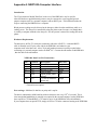
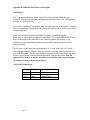
1
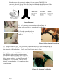
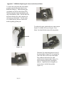
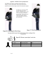
NIBP100A MANUAL - NONINVASIVE BP MONITOR Section 1 Safety Considerations……………………………………………………. 4 1.1 Warnings…………………………………………………………………... 4 1.2 Precautions and Limitations………………………………………………. 4 Section 2: Introduction……………………………………………………………… 5 2.1 Intended Use……………………………………………………………….. 5 2.2 General Description……………………………………………………….. 5 Section 3: Displays, Keys and Connectors………………………………………… 6 3.1 Front Panel………………………………………………………………… 6 3.2 Rear Panel ………………………………………………………………… 7 3.3 Side Panels……………………………………………………………….. 7 3.4 Sensor End of Patient Cable……………………………………………… 8 3.5 Description of Dedicated Keys…………………………………………… 9 3.6 Description of Soft Keys………………………………………………….. 9 3.7 Description of Display Contrast Dial……………………………………… 10 3.8 Description of Audible Indicators………………………………………… 10 Section 4: Set-Up and Usage……………………………………………………….. 11 4.1 Initial Set-Up………………………………………………………………. 11 4.2 Test Process……………………………………………………………….. 12 4.3 Sensor Application Process………………………………………………... 12 4.4 Display Screens……………………………………………………………. 16 4.4.1 Waveform Trend Display Screen…………….………………….. 17 4.4.2 Table Display Screen……………………………………………. 18 4.4.3 Graphical Reading Display……………………………………………… 19 4.4.4 Real Time Display……………………………………………………….. 20 4.5 Set-Up Screen……………………………………………………………… 21 4.5.1 Cycle Screens……………………………………………………. 21 4.5.2 Sensor Height Screen……………………………………………. 22 4.5.3 Alarm Set-Up Screen……………………………………………. 23 4.5.4 Set Clock Screen………………………………………………… 24 4.6 Special Screens…………………………………………………………….. 25 4.6.1 ‘GSD’ or TP245 Print Screen…………………………………… 26 4.6.2 ‘HP’ Print Screen………………………………………………... 27 4.7 Alarms……………………………………………………………………... 29 4.7.1 Patient Alarms…………………………………………………… 29 4.7.2 System Alarms…………………………………………………... 29 4.8 Printer……………………………………………………………………… 30 4.8.1 ‘TP201’ Printer Installation……………………………………… 30 4.8.2 “TP201 or TP245 ” Printer Operation………………………… 31 4.8.3 ‘HP’ Printer Installation…………………………………………. 32 4.8.4 ‘HP’ Printer Operation………………………………………….. 32 4.8.5 Trend Printing Operation………………………………………... 34 4.9 Data Port/RS232…………………………………………………………… 34 4.10 Analog Output…………………………………………………………… 34 Section 5: System Features and Specifications…………………………………….. 35 5.1 System Features…………………………………………………………… 35 Page 1 5.2 Technical Specifications………………………………………………….. 5.3 Performance Specifications……………………………………………….. Section 6: Troubleshooting 6.1 Troubleshooting…………………………………………………………… 6.2 Error and Warning Messages……………………………………………… 6.2.1 Non-Recoverable Errors…………………………………………. 6.2.2 Recoverable Errors………………………………………………. Section 7: Maintenance and Care…………………………………………………... 7.1 Service Policy……………………………………………………………… 7.2 Cleaning Procedures………………………………………………………. Section 8: Warranty………………………………………………………………... 8.1 One Year Limited Warranty………………………………………………. 8.2 Contact Information……………………………………………………….. Section 9 Accessories and Supply Information…………………………………….. Appendix A: Computer Interface…………………………… Appendix B: Real Time Screen Output………………………. Appendix C: Replacing the Sensor …………………….…… Appendix F: Wrist Strap Replacement………………………. Index of Figures FIGURE 1: F RONT PANEL…………………... FIGURE 2: REAR PANEL……………………. FIGURE 3 LEFT SIDE PANEL……………….. FIGURE 4: RIGHT SIDE PANEL……………... FIGURE 5: S ENSOR END OF PATIENT CABLE………………………... FIGURE 6: TEST SENSOR DISPLAY SENSOR…………………………. FIGURE 7: S ENSOR END OF PATIENT CABLE & HANGER…………… FIGURE 8: CORRECT S ENSOR PLACEMENT…………………………. FIGURE 8.1: S ECURING THE VELCRO STRAP………………………... FIGURE 8.2: PLACEMENT VERIFICATION…………………………… FIGURE 9: START MONITORING…………………………………….. FIGURE 10: WAVEFORM TREND DISPLAY SCREEN…………………. FIGURE 11: TABLE TREND DISPLAY SCREEN………………………. FIGURE 12: C YCLE S CREEN………………………………………… FIGURE 13: S ENSOR HEIGHT SCREEN ……………………………… FIGURE 14: WAVEFORM TREND SCREEN WITH SENSOR HEIGHT ICON……………………………………………………………… FIGURE 15: ALARM SET - UIP SCREEN ………………………………... FIGURE 16 SET CLOCK SCREEN ……………………………………… FIGURE 17: P RINT SCREEN – ‘TREND P RINT’……………………… FIGURE 17.1: ‘HP’ PRINT SCREEN………………………………... FIGURE 18: P RINTER I NSTALLATION……………………………… FIGURE 19: ‘TP 201 OR TP245’ PRINTOUT……………………. Page 2 6 7 7 8 8 12 12 13 13 13 14 17 18 21 22 22 23 24 26 28 30 31 36 37 38 38 39 39 41 41 41 42 43 44 44 44 46 48 50 51 Index of Figures (continued) FIGURE 19.1 ‘HP’ PRINTOUT …………………………………….…. FIGURE 21: WRIST PIECE SENSOR SLOT……………………………… FIGURE 22: WRIST PIECE CONDUCTOR END OF CABLE………………. FIGURE 23: INSTALLED SENSOR…………………………………….. FIGURE 23.1: PLACEMENT GUIDE INSTALLATION…………………. FIGURE 24: POLE BRACKET INSTALLATION…………………………. FIGURE 25: POLE ADAPTER INSTALLATION………………………….. FIGURE 26: WRIST STRAP INSTALLATION………………………….. FIGURE 27: SECURING THE INSTALLED WRIST STRAP……………….. FIGURE 28: MEASURE YOUR PATIENT WRIST CIRCUMFERENCE……... Revision History Rev A B C D E F G H I J K L ECO 99085 99085 99098 00045 00101 10080 10152 20064 30032 40028 40035 40099 Page 3 Date 11/01/99 11/01/99 12/15/99 05/01/00 09/01/00 05/01/01 09/17/01 07/08/02 08/29/03 05/06/04 05/10/04 11/16/04 33 49 49 49 50 51 51 52 52 52 SECTION 1: SAFETY CONSIDERATIONS 1.1 Warnings Carefully read all of the instructions and precautions described in this manual prior to clinical use of the NIBP100A Noninvasive Blood Pressure Monitoring System. 1. Place the NIBP100A system on a firm flat surface, assuring that the vents on the back and bottom panels are free of obstructions. 2. NIBP100A sensors are not sterile devices and should not be sterilized. ETO or autoclaving will damage sensors. 3. Using the NIBP100A in the presence of flammable anesthetics: represent an explosion hazard. 4. A power interruption will cause the NIBP100A system to stop monitoring. 5. Proper functioning of NIBP100A requires pulsatile arterial flow. The NIBP100A cannot be used during cardiopulmonary bypass or cardiopulmonary resuscitation. 6. The NIBP100A system is to be used only by trained medical personnel. 1.2 Precautions and Limitations 1. The NIBP100A may not operate effectively on patients experiencing tremors, arrhythmias or excessive movement. 2. The NIBP100A is not intended for use on patients during cardiopulmonary bypass. 3. To measure central pressure, the sensor must be at heart level to compensate for the difference in the NIBP100A reading due to the hydrostatic pressure differences. Approximate rule: for every 1" above or below heart level the sensor, 1.90mmHg should be added or subtracted to the displayed reading. 4. If a NIBP100A reading does not appear to correspond with other physiological parameters: • Verify the patient’s physiological state. • Check the patients body position to account for hydrostatic pressure differences. • Check the sensor placement. • Observe for motion or noise artifact. • Refer the system to a qualified service representative. Page 4 SECTION 2: INTRODUCTION 2.1 Intended Use The NIBP100A system is a noninvasive blood pressure monitor, which uses a pressure sensor placed on the wrist over the radial artery. This device is intended to be used on patients by trained medical personnel to continually monitor systolic, diastolic and mean blood pressure and pulse rate. The information from this device is intended to guide clinicians in the therapeutic management of their patients by: providing accurate and frequently updated blood pressure information in a safe, non-invasive, easily obtained, and comfortable manner. The device will not function in certain situations, including when patients are on cardiopulmonary bypass or any other conditions in which rendering a pulsatile pressure signal from the radial artery is unavailable. Also, since the NIBP100A intermittently compresses the radial artery, it should be used with caution in patients with absent ulnar artery collateral circulation. If the Allen’s test suggests that this is the case, the NIBP100A should not be used in continual mode. If the opposite arm has better ulnar collateral circulation, then this arm should be used instead. It should be recognized that this device is intended for use by competent, trained, healthcare providers that will determine a diagnosis based on many factors, of which the NIBP100A is one component. Incorrect readings due to such things as motion artifact are expected to be disregarded by the practitioner. The sensor placement and associated extremity should be periodically checked when the NIBP100A is used over a prolonged period of time. 2.2 General Description The NIBP100A system is a non-invasive blood pressure monitor that uses a pressure sensor placed directly on top of the radial artery. This sensor is noninvasive and eliminates the need for an occlusive inflatable cuff. This device is intended to be used on patients by medical personnel to continually monitor systolic, diastolic and mean blood pressure, and pulse rate. The NIBP100A uses a patented “sweep technique” which applies a varying force on the radial artery. The counterpressure in the artery produces a signal which is digitized and used to calculate blood pressure parameters. The sensor measures the pulse at the point of maximum energy transfer, the wave shapes are analyzed by Medwave’s proprietary algorithms. Parameters are extracted from the waveforms and a set of coefficients are applied to them yielding systolic, mean, and diastolic pressures approximately every 15 heart beats. These algorithms have been tested and validated in clinical studies by synchronized comparisons to arterial line pressure waveforms. Patient pressures can be monitored visually by viewing the screen and audibly entering limits into the NIBP100A alarm menu. Patient measurements above or below the limits will be automatically brought to the attention of the caregiver through these visual and audible alarms. A Start/Stop key provides the operator with an option to cancel operation at anytime. Page 5 SECTION 3: DISPLAYS, KEYS AND CONNECTORS 3.1 Front Panel Figures 1-4 show the front, rear, and side views of the NIBP100A and identifies displays, controls, indicators, and connectors. 6 1 2 7 3 8 4 5 Figure 1: NIBP100A Front Panel 12345678- Start/Stop Key Display Key Set-Up Key Mute Key System Soft Keys Systolic Display Diastolic Display Mean Display The keys on the front panel of theNIBP100A are used to access various program functions. Each key allows the operator to perform its function with a simple touch of the key. There are three dedicated keys to the left of the display and four soft keys at the bottom of the display. A dedicated key alarm mute is located in the lower right corner. Key functions are listed below. For additional information on how to use each key, please refer to Section 3.5. Page 6 3.2 Rear Panel Figure 2: NIBP100A Rear Panel 13 9 10 11 12 14 9 – Analog Input/Output Jack 10 - On/Off Power Switch 11 - Power Cord Connection 12 – Sensor Holder Cable Connection 13 - Data Port Connection 14– Mounting Nuts for Pole Mounting Bracket Accessory #000-9015 3.3 Side Panels 15 Figure 3: NIBP100A Left Side Panel 15 –Hanger for Sensor End of Patient Cable Page 7 Side Panels (continued) 16 - Display Contrast Dial 16 Figure 4: NIBP100A Right Side Panel 3.4 Senor End of Patient Cable 23 17 18 21 22 17 – Bale 18 – Bale Cord 19 – Wrist Strap # 413-0000 20 – Placement Guide Posts 21 - Sensor #400-0049 22 – Adult Normal Wrist Size 15 – 18 cm Placement Guide #374-0081 20 23 – Placement Guide Indicator Line 24 – Wrist Strap Loop Guide 24 Figure 5: Sensor End of Patient Cable Page 8 3.5 Description of Dedicated Keys The START/STOP key starts or stops monitoring. The DISPLAY key scrolls through two screens: Note: These screens can only be accessed after the daily self-test and TEST have been performed. Waveform Trend Display: Display of scaled pressure beats from the previous several sweeps. Table Trend Display: Scan through and display in tabular form, 5 of approximately 900 readings saved in non-volatile memory. Graphical Reading Display: Display of pressures and pulse readings in graphical form from fifteen minutes to eight hours. Real Time: Graphical display of the pressure signal as produced by the sweeping motor activity. The SETUP key scrolls through five screens: Cycle Time : Allows the user to select the length of time between pressure measurements. Sensor Height : Allows the user to enter the height difference between the wrist sensor and the heart level. Alarm Setup: Allows for selection of alarm values for Systolic, Diastolic, and Mean blood pressures and Pulse rate other than default values. Set Clock: Allows the user to set the internal clock to the correct time. Printer: Allows the user to select the printing mode for the optional printer. Located on the LOWER RIGHT corner of the front panel. MUTE: Silences the audible alarm for all recoverable errors. The bell symbol in the upper right corner of the display will appear with an “X” through it when the “MUTE” is activated. 3.6 Description of Soft Keys “Soft Keys” function with different menus. The screen label above the key indicates its function. These keys are not touch screen keys. Page 9 3.7 Description of Display Contrast Dial The Display Contrast Dial is used to adjust the on-screen clarity. It is located on the lower right side of the unit 3.8 Description of Audible Indicators The list below represents tones for which there is no accompanying symbol or button: One (1) second beep when the unit turned on. Refer to Section 4.7 for further description of alarms. Page 10 SECTION 4: SET-UP & USAGE 4.1 Initial Set-Up The NIBP100A System consists of (1) Monitor # 400-0051, (1) Patient Cable # 000-9002, (1) Power Cord #131-0011, (1) Placement Guide and (1) Placement Guide Kit and (1) Operator’s Manual # 797-0025. Your Patient Cable comes installed with a (1) Adult Normal Placement Guide for Wrist Sizes 15 – 18 cm, (1) Sensor # 000-9032 and (1) Adult Wrist Strap. The sensor must be replaced every 6 months. Sensor replacement programs are available through Medwave or an authorized Medwave Distribution Partner. 1. Unpack the NIBP100A System. Verify that all your components are included. Place the unit on a firm flat surface. The vents at the back and bottom must be free of obstructions. 2. Attach the power cord to the receptacle on the back panel directly below the power switch. Plug the power cord into an appropriate outlet. 3. Verify the Patient Cable is plugged into the connector located just below the power cord connection. 4. Turn the unit on. The power switch is located in the back of the unit just above the power cord. The NIBP100A automatically performs a Self-Test before displaying the Test Sensor Screen. 5. Proceed to TEST Process Section 4.2. Page 11 4.2 TEST Process A TEST process is required each morning after 5:00 AM, prior to use, or when a new sensor or patient cable is attached, or when damage to the sensor or patient cable is suspected. This TEST will check the integrity of the sensor. This screen will also display the number of days until the sensor expires. Once TEST process is completed, it is not affected by loss of power. Figure 6: Test Sensor Display Screen 1) Place the sensor end of the patient cable in the hanger on the left side panel of the unit as shown. Loop the bale over the top of the hanger tab, making sure the bottom of the sensor end of the patient cable engages the two locating pins of the hanger. Ensure the sensor end of the patient cable, wrist strap and cable hang freely from the hanger. 2) Press TEST soft key and observe status message on top line of screen. • • If ‘PASSED’ is displayed, proceed to step 3. If ‘FAILED’ is displayed, follow on-screen instructions. Figure 7: Sensor End of the Patient Cable & Hanger 3) Remove from the hanger and place the sensor on the patient. (See Section 4.3). Note: If the clock time in the upper right corner of the LCD is incorrect, press the SetUp key four times, followed by Select to set the correct time. When set, press Accept. This is further described in Section 4.5.4. 4.3 Sensor Application Process Once Test process has been completed, the monitor will display the Waveform Trend screen. Page 12 Select the correct placement guide and strap for your patient. The NIBP100A comes with the Adult Normal Wrist Size Range installed and a handy Placement Guide Accessory Kit. The Placement Guides are color-coded and labeled for easy selection: Adult Normal Large Adult Pediatric Black Guide Black Wrist Strap Wrist Sizes: 15 – 18 cm Gray Guide Black Wrist Strap Wrist Sizes: 18 – 22 cm Blue Guide Blue Wrist Strap Wrist Sizes: 11 – 15 cm Measure your Patient’s Wrist Circumference Sensor Placement 1. ) To locate proper sensor position, with one finger (a) palpate while you find the distal edge of the radius bone. a 2.) Place the sensor directly over this point (b). Secure the strap snugly (c). b Figure 8: Correct Sensor Placement c Figure 8.1: Securing the Velcro Strap 3.) The green indicator lines on the placement guide and the sensor will align to the distal edge of the radius bone (Figure 8.2). Place a finger through the access hole of the placement guide and feel the distal edge of the radius bone. Verify your nylon Velcro® strap is secure. Note: When set in the CONTINUAL cycle mode, the NIBP100A is designed to obtain and update accurate blood pressure readings once every 12-15 heart beats. Once the NIBP100A begins displaying blood pressure readings, you should see updated readings every 12-15 seconds. If the time lapse display is greater than the 12-15 seconds are, check your placement. Figure 8.2: Placement Verification Page 13 Sensor Application Process (continued) 4.) Press start to begin monitoring. Your first reading will take approximately fifteen heartbeats. Figure 9: Start Monitoring 5.) Always conclude the monitoring session by pressing the start/stop key prior to removing sensor from patient. Once the NIBP100A displays the initial pressure reading, it does not require additional adjustment. If the NIBP100A is not providing reading, the strap tension may need to be adjusted or the sensor repositioned. (Refer to Section 4.3 of this manual). Patient movement or motion artifact may also cause missed readings, this will be noticeable on the arterial waveform on the Waveform Trend screen. The system requires the initial strap tension to be within acceptable limits before it allows monitoring to begin. Note: The first reading may take up to 30 seconds. During this time it is especially important the wrist remain still. Page 14 Sensor Application Process (continued) NOTE Accurate and repeatable operation of the NIBP100A System is dependent upon the proper preparation and placement of the sensor. It will tolerate some flexibility in placement. However, for best signal, placement needs to be over a hard surface, not where tissue is soft. Optimum sensor position occurs when the sensor signal is the clearest, and the signal strength bar is at its maximum height. In addition, consistent arterial waveform readings are obtainable with proper placement. If sensor placement is in question, these two parameters (Arterial waveform consistency and sensor signal clarity) may be used as indications of improper sensor placement. Page 15 4.4 Display Screens DISPLAY MODES Repeatedly pressing the DISPLAY key scrolls through four different screens: Waveform Trend Display Table Trend Display Graphical Readings Display Real Time. Page 16 4.4.1 Waveform Trend Display Screen The Waveform Trend Screen displays the patient’s arterial waveform and pressure readings. This screen is designed to be used for routine monitoring. Figure 10: Waveform Trend Display Screen SCALE UP ⇑ DOWN ⇓ AUTO HMT: OFF HMT: ON When UP or DOWN is selected, moves the graduations of the graph 40-100; 30- 150;20-200;10-250;0-300. Increases the mmHg scale to provide maximum viewing of the signals. Decreases the mmHg scale to provide greater viewing of signals. Automatically scales the graduations of the graph as the waveforms are displayed. Turn High Motion Tolerant Algorithm (HMT) off and on. Default is HMT: OFF. HMT: OFF should be used when patient is engaged in little or no motion. HMT: ON should be selected when the patient is in motion and the caregiver desires a higher level of motion tolerance. When HMT: OFF is displayed, the high motion tolerant algorithm is not activated. When HMT: ON is displayed, the high motion tolerant algorithm is activated. Press the soft key to toggle between choices. Note: HMT:ON should be selected only when the patient is in motion and the caregiver desires a higher level of motion tolerance. When the patient is resting or engaged in little or no motion, select HMT:OFF. Always begin your monitoring session with HMT:OFF. Monitor your patient for 5 readings to establish a baseline prior to selecting HMT: ON. Always secure 4”6” of the patient cable to the patient’s forearm to prevent excessive cable movement. For those caregivers who have a specific and predictable patient activity monitoring session HMT: AUTO may be your choice. Press the soft key below the screen prompt The HMT:OFF and scroll to the HMT:AUTO prompt. Insure that your patient is resting or is in little or no motion. Complete five consecutive readings. After the fifth reading is displayed, you will not be required to press a soft key - the high motion tolerant filter is activated automatically – Remember - your patient must begin the higher constant motion. OO:O8 Lapsed time since displayed reading. ---Inactive Key Note: While monitoring, if no keys are pressed for a period longer than one minute, the NIBP100A automatically reverts back to the Waveform Trend Screen. Note: When the sensor height option is selected and in use, the sensor height icon will appear on the left-hand side of screen. (Refer to Figure 13). Page 17 4.4.2 Table Display Screen The Tabular Trend Display Screen displays the patient’s blood pressure, mean, and pulse rate in tabular form. This screen is selected by toggling the Display Key. Figure 11: Table Trend Display Screen SCAN FWD Allows the user to scroll forward in time SCAN BACK CLEAR Allows the user to scroll back in time to view previous readings. Eases all of the trend data, including waveform and graphical trend data. When this option is selected, a confirmation notice is displayed with YES and NO options. If YES, is chosen, the data is erased; if NO is chosen, you are taken back to the trend screen. Allows the user to change the frequency of data displayed: All readings, 1 minute, 3 minutes, 5 minutes, and 15 minutes. TABLES Page 18 4.4.3 Graphical Reading Display The Graphical Reading Display Screen displays the patient’s blood pressure, mean, and pulse rate in graphical forms over a selected period of time. Figure 11.10: 15 Min S/D Graph Display MEAN SYS/DIA PULSE TIME User is able to view graphical display of Mean Pressure readings. User is able to view graphical display of Systolic and Diastolic readings. User is able to view graphical display of Pulse readings. Changes the increments that are displayed on the graph. Toggles through display increments of 15, 30 minutes, 1,2 4, 8 hour Page 19 4.4.4 Real Time Display The Real Time Display Screen displays the pressure signal as produced by the sweeping motor activity. This signal is NOT the patient’s blood pressure waveform in mmHg. The pressure graphically displayed is the amount of pressure being sweeped against the patient’s wrist. Figure 11.20: Real Time Display Screen SCALE ⇓ SCALE ⇑ ERRORS Reduces the graphical scale to provide maximum viewing of signal. Increases the graphical scale to provide Minimum viewing of signal. Accesses a numeric coded error log for troubleshooting technical phone support Page 20 4.5 Set-Up Screens SET-UP MODES Repeatedly pressing the SET-UP key scrolls through five different screens: Cycle ( See Section 4.5.1) Sensor Height (See Section 4.5.2) Alarms (See Section 4.5.3) Set Clock(See Section 4.5.4 Printer (if option is enabled) (see Section 4.6.1) 4.5.1 CYCLE Screen The CYCLE Screen allows the user to select the length of time between pressure measurements. You may make an immediate (STAT) measurement except in the continual mode. Figure 12: Cycle Screen CYCLE: STAT: --- Adjusts the time between pressure measurements. Cycle Time is CONTINUAL, 1 minute, 3 minutes, 5 minutes, or 15 minutes This value is stored and selected whenever power is cycled. Takes continual readings for one minute then reverts to previously set cycle time. These three dashes will appear when STAT key is inactive. Page 21 4.5.2 SENSOR HEIGHT Screen To measure central pressure, the sensor must be at heart level to compensate for the difference in the NIBP100A reading due to the hydrostatic pressure differences. Approximate rule: for every 1" above or below heart level the sensor, 1.90mmHg should be added or subtracted to the displayed reading. The SENSOR HEIGHT Screen allows the user to enter the height difference between the wrist sensor and the heart level. The range is 12 inches (30 cm) above the heart to 24 inches (62 cm) below the heart. Figure 13: Sensor Height Screen SENSOR ? Decreases the height difference between the sensor housing and the heart level in one-inch increments. Range is 1 through 24 inches. SENSOR?? Increases the height difference between the sensor housing and the heart level in one-inch increments. Range is 1 through 12 inches. INCH CM OFF ON Selects inches or centimeters as the height units. Turns feature off or on. Default is OFF; height difference is set to zero. Note: When the sensor height option is selected and in use, the sensor height icon will appear on the left hand side of screen.(Refer to Figure 14). Figure 14: Waveform Trend Screen with Sensor Height Icon Page 22 4.5.3 Alarm Set-Up Screen ALARM SET-UP Screen allows for customizing alarm values for systolic, diastolic, and mean blood pressures and pulse rate. Figure 15: Alarm Set-Up Screen (Default Settings) SELECT: Selects the desired parameter. The selected parameter will be indicated by a solid, vertical bar. HI LMT: Moves the high limit up for the selected parameter in increments of 5mmHg, until the maximum value allowed for that parameter is reached. The limit then "rolls over" to the minimum value allowed for that parameter. LO LMT: Moves the low limit down for the selected parameter in increments of 5mmHg, until the minimum value allowed for that parameter is reached. The limit then "rolls over" to the maximum value allowed for that parameter. DEFAULT: Returns to Default settings as shown in Figure 15. Alarm Parameter Ranges High Limits High Limit Default Low Limits Low Limit Default Systolic 75 – 250 240 40 - 150 40 Mean 60 – 200 140 30 - 130 30 Diastolic 40 – 180 130 20 - 120 20 Pulse Rate 60 – 200 200 40 - 120 40 Page 23 4.5.4 Set Clock Screen The SET CLOCK Screen controls setting of time and will bring up this screen: Figure 16: Set Clock Screen SELECT: Moves cursor to the hours or minutes. INCREASE: Increases the numerical values of the selected parameter. DECREASE: Decreases the numerical values of the selected parameter. ACCEPT: Sets the clock to the time and date on the screen. NOTE: The time is displayed in 24-hour format. To exit this screen without changing time, press one of the keys on the left of the screen (START/STOP, DISPLAY, or SETUP). The date is factory set and may be changed only by increasing or decreasing the hours through a 24-hour period. Page 24 4.6 Special Screens: Self Test Screen: Appears only during power up. Test Screen: Test for sensor performance and integrity before allowing the system to proceed. See Section 4.2 for details. Page 25 4.6.1 ‘GSD’ or ‘TP45’ Print Screen You will need to initially configure NIBP100A for a printer option ‘TP245/245’, ‘GSD” or ‘HP” see Section 4.8 for details. The PRINT screen allows for selecting printing mode and for tabular trend table (Table Display - Section 4.4.2) data to be printed if the NIBP100A System is equipped with a printer. The screen will display initial time values for the printing from when the unit was turned on to the current time. Press PRINT NOW to print the tabular data since the unit was last turned on (in 5-minute increments). The NIBP100AA may continue to be used while the printer is in operation. The top line of the screen will indicate the printer type. The printer type is stored permanently in memory, however, there is a provision for connecting to other equipment. If you wish to connect the NIBP100A to a general-purpose computer with an RS232 serial port see Appendix A. Figure 17: Print Screen - 'Trend Print' Mode Selected PRINT MODE: Choices are 'Trend print' or 'Print as BP's occur'. 'Trend print' is the default value after power up. In this mode, pressure readings from the tabular trend table will be sent to the printer only when the PRINT NOW key is pressed. When 'Print as BP's occur' mode is selected, each successful blood pressure (BP) determination will be sent to the printer immediately. Trend printing is not available in this mode, so the system soft keys are blanked accordingly, and the trend time selections are labeled '(inactive)'. PRINT FROM: Page 26 Indicates the time of the oldest data to be printed. Default value is when the unit was most recently turned on. May be changed in 1 hour increments with the INCREMENT or DECREMENT keys, but may not be decreased past the oldest data in the trend table, nor increased past the 'PRINT TO' time. ‘GSD’ or ‘TP245’ Print Screen (continued) TO: Indicates the time of the most recent data to be printed. Default value is the current time. May be changed with the INCREASE or DECREASE keys like the 'PRINT FROM' time field, but may not be increased past the current time, nor decreased closer than 30 minutes to the 'PRINT FROM' time. INTERVAL: Indicates the tabular trend table from which data is printed. Default is 5 minutes. Choices are the same as the tabular trend tables (1, 3, 5, 15 or All readings). May be changed with the INCREASE or DECREASE keys. ‘GSD’or‘TP245” Print Screen Soft Key Descriptions : SELECT: Moves cursor to the desired parameter (MODE, PRINT FROM, TO or INTERVAL). MODE: Toggles the printer mode. Choices are 'Trend print' or 'Print as BP's occur'. 'Trend print' is the default value after power up. In this mode, pressure readings from the tabular trend table will be sent to the printer only when the PRINT NOW key is pressed. When 'Print as BP's occur' mode is selected, each successful blood pressure (BP) determination will be sent to the printer immediately. Trend printing is not available in this mode so the system soft keys are blanked accordingly and the trend time selections are labeled '(inactive)'. PRINT NOW: Starts printing the selected data. Key will change to CANCEL once started. You may continue to use the NIBP100A while printing is in progress. CANCEL: Stops printing of data. There may be a delay of a few secon as the printer finishes printing a reading. Key will change to PRINT NOW when pressed. 4.6.2 ‘HP’ PRINT Screen The top line of the screen should read PRINTER: HP. The ‘HP’ PRINT screen allows you to select the total amount of data to be printed on the HP DeskJet printer. The screen will display the initial values for printing. The PRINT FROM: default is set to 2 hours prior to the last data record in memory. The TO: default is set to the date and time of the last data record in memory. The TOTDATA: default is two hours. The user can select the TOT-DATA: only. Your selection can be 20 minutes, 1 hour, 2 hours, or 5 hours. Press PRINT NOW to print the selected amount of data to the printer. The Vaostrac Model APM205A may continue to be used in normal mode while the printer is in operation. Page 27 “HP’ PRINT Screen (continued) Figure 17.1: HP PRINT Screen TOT-DATA: PRINT FROM: TO: Indicates the amount of data to be printed. Default is 2 hours. Using the INCREASE and DECREASE keys the user can choose to print 20 minutes, 1 hour, 2 hours, or 5 hours of data starting from the most recent recording. The setting can not be decreased more than 5 hours from the TO: date and time, nor increased past the TO: date and time. Indicates the start time of the data to be printed. This value is determined by your selection. It is based on the TOT-DATA: selection of a prior time period to the date and time of the last record in memory. This field cannot be modified by the user. Indicates the date and time of the last record in memory. This field cannot be modified by the user. The printer type is stored in memory, however, there is a provision for connecting to other printers and equipment. If you wish to connect the NIBP100A to the TP245 thermal printer. Refer to Section 4.8.1 on ‘TP245 Printer Installation’ and 4.6.1 ‘GSD’ or ‘TP245 PRINT’ Screen. To connect to a ‘GSD’ general-purpose computer with an RS232 serial port see Appendix A and 4.6.1 ‘GSD’ or ‘TP245’ PRINT Screen . Print Screen Soft Key Descriptions : PRINT NOW: Starts printing selected data. Key will change to CANCEL once printing has started. You may continue to use the NIBP100A while printing is in progress. CANCEL: Stops printing of data. There is a delay of up to 20 seconds as the printer finishes canceling the current print job. The message ** canceling ** is put up while canceling is in progress. You may continue to use the NIBP100A while canceling is in progress. Page 28 4.7 Alarms The NIBP100A has both audible and visual alarms. When an audible alarm can be silenced by pressing the "MUTE" key at any time (except in the case of non-recoverable system errors). When the "MUTE" key is pressed, the bell symbol in the upper right corner of the display will appear with an “X” through it. In the case of patient alarms, the pressure value that has set off an alarm will continue to "flash" until the condition is resolved, even when the "MUTE" key has been pressed. 4.7.1 Patient Alarms Defined as those alarms tripped when the patient’s blood pressure or pulse rate goes above or below the predetermined limits. (See Section 4.5.3 for adjusting these limits). Event Blood pressure, mean, or pulse rate reading is above or below the set limits. Flashing Alarms Display Indicated by (- - -) for the corresponding pressure reading. Audible Alarms Three (3) beeps, pause, two (2) beeps, pause, three (3) beeps, pause, two (2) beeps repeated every 15 seconds until muted or until the condition causing the alarm is corrected. 4.7.2 System Alarms The NIBP100A has an alarm that activates when multiple readings have been missed and takes certain actions to inform the user of its findings. Sweep Cycle Time Continual (10 seconds) 1 minutes 3 minutes 5 minutes 15 minutes Flashing Cycle time + 3 minute Cycle time + 3 minute Cycle time + 3 minute Cycle time + 3 minutes Cycle time + 3 minutes Monitoring Stops Cycle time + 10 minutes Cycle time + 10 minutes Cycle time + 10 minutes Cycle time + 10 minutes Cycle time + 10 minutes The NIBP100A may be equipped with an optional printer. The printer is attached to the top of the NIBP100A with a bracket and is connected by cable to the Data Port on the rear of the device.(Refer to Figure 18). Page 29 4.8 Printer You may need to initially configure your NIBP100A. This is done by holding down the 'start/stop' key while turning on the NIBP100A power switch. A brief message will appear on the Self-Test screen which should show one of the following: 'PRINTER:TP245' or 'PRINTER:GSD' or ‘PRINTER:HP’ or 'PRINTER:NONE' release the key at this point. The message indicates either thermal printer (TP245) or general serial device (GSD, described in appendix A), Hewlett Packard DeskJet ? printer (HP). To activate the HP option, please call Medwave’s Technical Support Department at 800-894-7601) or no printer (NONE) was selected. You will need to power off/ power on while holding down the 'start/stop' key to toggle between 'PRINTER:TP245' or 'PRINTER:GSD' or ‘PRINTER:HP’ or 'PRINTER:NONE' selections. Your selection will be stored in memory. 4.8.1 ‘TP245’Printer Installation You need the 'PRINTER:TP245' to connect to the Medwave printer # 400-0011. If the NIBP100A is set for 'GSD' or ‘HP’ data will appear garbled on the printer or the print setup screen. If the NIBP100A is set for ‘NONE’ the Print screen will not appear. ‘GSD’ is an option for general-purpose computer such as a personal computer interface. Details on’GSD’ is described in Appendix A. ‘HP’ is an option to print data on a Hewlett Packard DeskJet printer. To activate this option, please call Medwave’s Technical Support Department at 800-8947601. You will find additional information on ‘HP’ Printer Selections in Section 4.6.2 and Section 4.8.4 If 'NONE' is selected, the print screen will be bypassed when using the setup key. Make sure power is off to the NIBP100A before attaching the printer. The TP245 printer will have a mounting bracket. The TP245 printer has dual lock fasteners. Either printer mounts to the top of the top of the NIBP100A to the right side as shown, by inserting the clip in the slots on the rear of the device and then slipping the bracket hooks over the front edge of the monitor. The cable should be attached and the screws secured finger tight only. Use only the Medwave supplied cable #131-0014. It has been specifically designed to supply power to the printer. Figure 18: Printer Installation (rear view) Page 30 4.8.2 ‘TP245’ Printer Operation To activate the TP201 or the TP245 printer, move the printer power switch to the middle position. The printer is powered from the NIBP100A, so it may be turned on before or after power is applied to the NIBP100A. One blank line is printed when the printer is turned on. When printing begins, the printer will print a standard header with information as follows: Medwave Vasotrac APM205A Patient__________________ Physician________________ Procedure________________ mmHg 20 60 100 140 180 | | | | time sys/dia |♥bpm(map) Figure 19: TP201 or TP245 Printout Whenever pressures are printed, the value will be printed as follows: Date:97-OCT-14 14:22 [ ^ ] 110/68 ♥ 66(91) 14:22 [ ^ ] 122/82 ♥ 72(101) The graphic values will be lined vertically with the scale, such that if the paper strip is turned sideways, a graphical trend can be discerned. The " [ " is diastolic pressure, " ^ " is mean arterial pressure (map), " ] " is systolic pressure and " ♥ " is the pulse in beats per minute(bpm). The numeric values are shown to the right of the graphic portion per the legend in the header. Page 31 4.8.3 ‘HP’ Printer Installation You need ‘PRINTER: HP’ to connect to the HP DeskJet printer. If the NIBP100A is set for ‘GSD’ or ‘TP245’ data will appear garbled on the printer. If ‘NONE’ is selected, the HP Print screen will be bypassed when using the setup key. Disconnect the NIBP100A from the patient. Move the HP Desk Jet printer away from the patient. Make sure the power is off to the NIBP100A and the HP DeskJet printer before connecting. Use only the P/N 000-9017 HP printer cable provided by Medwave, Inc. to connect to HP DeskJet models 345, 350C, 350Cbi, 630C, 640C or 648C. Connect the end marked ‘PRINTER’ to the parallel port of the printer. Connect the end marked ‘VASOTRAC’ to the data port of the NIBP100A. Turn on the printer and then turn on the NIBP100A. 4.8.4 ‘HP’ Printer Operation For each print job, the printer will print one page containing a header, bar graph and table data. Refer to a sample printout Figure 19.1. The header contains the date, printed in the YY-month-DD format. A Patient ID field and a Doctor field are provided for user completion. The bar graph may have up to 24 bars that represent the data collected over the period of time the user previously selected. The y-axis scale represents pressure in mmHg and is set to 40220 mmHg. The x-axis scale is set to the first and last times of the actual data available for printing. The time of the data is represented as hours-minutes. A ‘(+1)’ is used when the data collection occurred over the midnight hour. The bars have three hash marks. The top hash mark denotes the systolic pressure, the middle hash mark denotes the mean pressure, and the lower hash mark denotes the diastolic pressure. If any of these pressure values go beyond the graph scale of 40-220 mmHg the bars are clipped and a message “Data exceeds graph scale” is printed below the graph. The table of pressure values contains up to 40 data values covering the time selected by the user. The table data is organized in time sequence, two columns, each containing up to 20 readings, printing from the left column to the right column. A ‘(+1)’ is printed before a time value when the data collection occurred over the midnight hour. The time field is followed by pressure values in mmHg and the heart rate in beats per minute. NOTE: The date and time of the first table entry may not coincide with the PRINT FROM: date and time of the PRINT screen. Remember, if data is not available in the memory of the NIBP100A for the TOT-DATA: selection , then the first table entry will correspond to the time of the oldest data record available. Page 32 Vasotrac APM205A Date: 00-SEP-25 Patient Id: _______________ Doctor: ___________ 220 mmHg 160 sys mean 100 dia 40 23:40 time (+1) 00:40 *** Data exceeds graph scale *** the graph scale of 40-220mmHg) (only printed if systole, mean, or diastole values exceed time 23:39 23:42 23:45 23:47 23:50 23:53 23:56 23:58 (+1)00:01 00:03 00:06 00:09 00:11 00:14 00:17 00:20 HR 78 77 76 73 76 77 78 74 76 79 72 72 74 72 75 74 syst 123 121 120 117 121 126 129 133 133 127 133 137 134 137 145 143 Page 33 dias 85 85 88 82 86 81 88 92 93 91 90 86 93 100 98 99 mean 105 103 108 100 105 101 108 115 115 110 112 115 115 117 120 119 time 00:23 00:26 00:29 00:32 00:35 00:37 00:40 syst 150 142 139 139 133 130 130 dias 102 96 100 91 95 87 82 mean 125 123 120 112 115 111 107 Figure 19.1 HP Printout HR 71 75 74 76 78 73 75 4.8.5 Trend Printing Operation The operator may choose to print data when monitoring is complete using the data stored in the tabular trend table. Section 4.8 describes the screen and keys necessary to print this data. 4.9 Data Port / RS232 The NIBP100A may be connected to an external computer (in place of the printer) using the RS232 Data Port on the rear of the device. See Appendix A for further details on computer interface. Note that only equipment meeting UL2601-1 or EN60601-1 standards should be connected to preserve electrical safety. 4.10 Analog Output The NIBP100A may be connected to an strip chart recorder or other recording device using the Analog I/O port on the rear of the device. This will record a single wave shape for each pressure determination. See appendix B for further details wave form output.. Note that only equipment meeting UL2601-1 or EN60601-1 standards should be connected to preserve electrical safety. Page 34 SECTION 5: SYSTEM FEATURES AND SPECIFICATIONS 5.1 System Features NONINVASIVE: Eliminates those risks associated with invasive monitoring to the patient and caregiver. MICROPROCESSOR BASED DESIGN: Provides reliable, high speed digital signal processing. ARTIFACT REJECTION: Advanced programming allows the system to identify and eliminate some noise and motion artifact. Automatic Pressure Zeroing: The microcomputer remembers the zero pressure offset even when power is off. AUDIBLE & VISUAL ALARMS: Audible and visual alarms for systolic, diastolic and mean pressures and pulse rate can be set to individual parameters or preset default values. Additional alarms will alert the caregiver of any abnormal condition or failure with the system. LCD and LED DISPLAYS: LCD display provides the caregiver viewing of the pressure waveforms, trending, and alarms settings. LED displays provide clear, continuous readout of patient blood pressure value. ANALOG I/O JACK: Provides an analog output signal for external recording. DATA PORT: Provides data for the optional printer or external computer. Page 35 5.2 Technical Specifications Product Description: BIOPAC NIBP100A Noninvasive, Continual Arterial Blood Pressure Monitor Physical Description: Case: Aluminum Size: 5” (h) x 4.5” (w) x 8.5” (l) [13 cm x 12 cm x 21.5 cm] Weight: 5 lbs. [2.5 kg] with power cord and patient cable (approximate) Displays: Liquid crystal (LCD) with Cold Cathode Fluorescent (CCF) back light Size: 2.5” (h) x 4.5” (w) [6.4 cm x 11.4 cm] Three (3) high intensity light emitting diodes (LED’s) Size: .75” (h) x 1.5” (w) [1.9 cm x 3.8 cm] Safety Classification: The NIBP100A is classified to U.S. and Canadian safety standards by Underwriters Laboratories Inc. with respect to electric shock, fire and mechanical hazards only in accordance with UL2601-1 and IEC 60601-2-30, and with CAN/CSA C22.2 No. 601.1. Control number 39RM. Classification: Class I equipment. Type: BF, defibrillation proof. Fluid protection: Ordinary Equipment (monitor and printer). Drip proof (IPx1) for patient cable housing only. Equipment is designed for continuous usage, as programmed by the user. Equipment is not suitable for use in the presence of a flammable anaesthetic mixture. See warnings section. The monitor has line voltage present inside the case. Refer servicing to a qualified technician 0123 Marking by this symbol indicates compliance with the medical Device directive 93/42/EE Electrical: Input: Fusing: 100-240 VAC, 50-60 Hz, 0.25 - 0.5 Amp. Two 5x20mm, 2 Amp, fast acting, 250 volt. Recommended replacements: Littlefuse series 217 or 235, Wickmann series 191 or 19193 or Bussmann series GMA or GDB. Electromagnetic Compatibility: Complies with the requirements of IEC 601-1-2: 1993 for electromagnetic emissions and immunity. Environmental - Operating: Temperature: 10°C to 40°C (50°F to 104°F) Humidity: 10% to 90% RH, non-condensing Environmental - Storage & Transport: Temperature: Humidity: -20° C to 70° C (-4°F to 158°F) 10% to 90% RH, non-condensing Equipment Interface: Data Port/RS232: 25 Pin RS-232, see appendix A for details. Analog I/O: ¼” Standard Phone Jack, see Appendix B for details. Page 36 5.3 Performance Specification Performance Systolic Mean Diastolic Pulse Trend Range Accuracy Min/Max 40 mmHg-240 mmHg ± 5 mmHg/SD 8 mmHg 30 mmHg-200 mmHg ± 5 mmHg/SD 8 mmHg 20 mmHg-180 mmHg ± 5 mmHg/SD 8 mmHg 40 bpm - 200 bpm ± 5 bpm or 10% Updated tabular following each reading, approximately 900 readings. Blood pressure measurements determined with this device are equivalent to those obtained by an intraarterial blood pressure measurement device, within the limits prescribed by the American National Standard, Electronic or automated sphygmomanometers. The proposed ANSI/AAMI SP10-1992 Standards are: For systolic and diastolic pressures, treated separately, the mean difference of the paired measurements of the test system and the comparison system shall be + or - 5mmHg or less with a standard deviation of 8mmHg or less. At minimum cycle time setting: Determination Time * Systolic Mean Diastolic Pulse Rate Trend ~ every 15 seconds ~ every 15 seconds ~ every 15 seconds ~ every 15 seconds Updates following each BP reading * ** Range Min/Max 40mmHg - 240mmHg 30mmHg - 200mmHg 20mmHg - 180mmHg 40bpm - 200 bpm Approximately 900 readings in tabular mode. Accuracy (mean difference) ** ±5mmHg / SD 8mmHg ±5mmHg / SD 8mmHg ±5mmHg / SD 8mmHg ± 5bpm or 10% Determination time will vary depending on the pulse rate. The minimum cycle (occurs at high pulse rates) is 10 seconds. The minimum or “continual” cycle is 14 beats plus the time to retract the sensor, plus the time to step from fully retracted to 50% of the previous valid mean pressure. In recovery sweep mode (after power on or a recoverable error) there is no step up and a slow default motor speed. Recovery sweeps, therefore, take somewhat longer (20 to 25 seconds generally). The cycle time may be set by the user to be greater than the minimum. Refer to section 4.6.1, “Cycle Setup.” Pressure accuracy specifications are based on clinical data. The pressure range of this clinical data was less thahe range min/max specification. Page 37 SECTION 6: TROUBLESHOOTING 6.1 Troubleshooting Guide If the NIBP100A is unable to take pressure readings, the pressure and heart rate numeric displays will all flash in unison. In the case of certain errors, the NIBP100A will automatically discontinue monitoring. In either of these two cases the user should then make an assessment of the system to look for one or more of the following possible causes: Cause Artifact caused by patient movement Improper strap tension Possible Solution Immobilize the patient’s arm Tighten or loosen strap as directed by screen instructions. Verify patient’s wrist size is in range of Placement Guide and Wrist Strap in Use. Improper sensor placement Check the placement of the sensor on the patient (refer to Section 4.4) Restriction of sensor movement Check that the sensor is not being compressed by any force other than the strap ΝΙΒP100Α component Check the sensor for leaks. Replace the sensor and run the failure TEST process. No Display Check Contrast Dial Check Power Cords, Plug, and Power Connection Check On/Off Switch Check Sensor Placement No Signal Display Check Sensor Connections Check Sensor Wires For Breaks Check Sensor Placement NIBP100A resets and Check Sensor Connections Runs Self Test Check Patient Cable for Breaks Printer screen error displayed 'HP Verify the printer cable is P/N 000-9017. offline'. Resets to Printer: HP screen Verify NIBP100A is connected to HP DeskJet models in 5-10 seconds. No data has printed. 345, 350C, 350Cbi, 630C, 640C or 648C. Printer screen displays the CANCEL Verify the printer cable is P/N 000-9017. key, resets to Printer: HP screen in 60 Verify NIBP100A is connected to HP DeskJet models –120 seconds. No data has printed. 345, 648C or 952C. Check printer cable connection. Power printer off/on. Check printer is powered on. Power printer off/on. Check paper in printer. Power printer off/on. Check paper path clear. Power printer off/on. 38 Page 6.2 Error and Warning Messages Error messages will appear on the LCD display to alert the user of system errors. There are several system alarms to alert the operator to abnormal conditions with the internal system or with a particular reading. System alarms fall in one of two categories: 1) Recoverable and 2) Non-Recoverable errors. 6.2.1 Non-Recoverable Errors All non-recoverable errors will halt system operation and will require intervention by either the user or a service technician to repair or adjust the unit to eliminate the malfunction. A screen error message will be displayed giving specific details of the error. An alternating ON-OFF alarm will sound in case of severe system hardware problems, until the unit's power is switched off. Certain non-recoverable errors will cause the system to discontinue monitoring, and switch itself to an auto-shutdown screen. In these cases, the user may be able to remedy the cause of the error and then restart the monitoring process by pressing the “START/STOP” key twice. The first selection of the “START/STOP” key switches the system to the SENSOR PLACEMENT screen, the second selection initiates monitoring. Note that the system will automatically retract the sensor when monitoring is discontinued, and as always during retraction, the keys are disabled. An audio alarm is emitted for these types of errors . ERROR MESSAGE CAUSE REMEDY NON-RECOVERABLE ERRORS: "SYSTEM ERROR CALL FOR SERVICE" "WRONG SENSOR TYPE FOR THIS MODEL” "Sensor signal at high limit" "Memory alloc error in new_xxx" "NO SIGNAL" Page 39 “Error in memory”: Memory corrupted. Possible AC line transients, EMI, or faulty component. “Error in object allocation”: generally occurs only on power up. No audible alarm is sounded. During power-on self-test, the NIBP100A has determined that the attached sensor is the incorrect type. During power-on self-test the main sensor signal was at its highest pressure. Insufficient memory is available. Indicates damaged component(s). The expected sensor signal is absent. The system automatically discontinues pressure monitoring. Turn system off and restart. If error persists, contact authorized service technician. Turn system off. Replace with sensor labeled SENSOR FOR APM205A. Restart. Check all electrical connections to the patient cable and sensor. Also verify that high pressure is not being applied to the sensor face. Refer to an authorized service technician. Check if the sensor is on the patient. Check sensor cable for damage. For repair or replacement, contact an authorized service technician. NON-RECOVERABLE ERRORS: ERROR MESSAGE CAUSE "BAD VOLTAGE" An internal power supply is at an incorrect voltage. The system automatically discontinues pressure monitoring. "NO READINGS" "SENSOR FAILURE" "SIGNAL HIGH" REMEDY Inspect sensor and patient cable cord for cuts and/or fraying. Replace any damaged parts. Press Start/Stop key to proceed. If error persists, pull the NIBP100A from service and call an authorized BIOPAC service representative. Consecutive invalid readings have occurred Verify proper sensor placement. for 10 minutes. Verify strap tension. Verify position of patient. Verify wrist is not in motion. Press Start/Stop key to proceed. If error persists, pull NIBP100Α from service and contact service representative. ERROR A105 has repeated for 4 consecutive Run a Zero/Test Procedure. sweeps. This is caused by an incorrect Inspect the sensor for leaks. If relationship on the main and auxiliary pressure leaks are detected or the sensor sensors. Indicates a sensor leak. fails the plate test, replace the sensor. Sensor pressure on the patient has gone above Verify sensor plugs into the its allowed limits for 10 beats or 19 seconds. patient cable housing. Verify Generally indicates damaged or missing patient cable is connected to the components. The system automatically monitor. Verify strap tension. discontinues pressure monitoring. Verify position of patient. Press Start/Stop key to proceed. If error persists, pull NIBP100A from service and contact service representative. “WRIST UNIT Failed” During power-on self test or during use, the NIBP100A was unable to detect the full extension of the sensor end of the patient cable. “LOOSEN/REMOVE STRAP” After a “WRIST UNIT Failed” error, the pressure on the patient’s wrist, as measured by the sensor, is not low enough. 40Page Remove sensor from patient. Power Off/On. If error persists, pull the NIBP100A from service and call authorized service rep. Loosen and/or remove the strap from the patient’s wrist. 6.2.2 Recoverable Errors These errors will not halt system operation but will prevent any new pressure values from being displayed until the cause of the error is remedied. If consecutive recoverable errors last longer than 70 seconds (at the minimum cycle time setting), a message on the LCD will indicate the time when the last valid reading occurred, and the LED's will flash until the error has recovered. The LCD display is the error message area. The message displayed will be the highest priority message which occurred since power on in the case of non-recoverable errors, or since the previous sweep in case of recoverable errors. SECTION 7: MAINTENANCE AND CARE 7.1 Service Policy The monitor portion of the NIBP100A does not require any routine maintenance. Should service be required, it should be performed by a qualified technician. All maintenance and repair procedures should be directed to BIOPAC. To obtain information on or order repair parts call BIOPAC Sytems, Inc.at 805-685-0066, or e-mail: [email protected]. For authorization and instructions for repair service, contact your local Field Service Representative. Provide the following information: Your Name Hospital Name Address Telephone Number Facsimile Number You will be advised of the corrective action to take. Page 41 Monitor S/N Patient cable S/N Sensor S/N Describe the problem E-mail Address 7.2 Cleaning Procedures Sensor Cleaning Procedures The sensor face should be cleaned after each use. Clean the surface of the sensor by wiping with a damp cloth. Preferred cleaning solutions are 70% isopropyl alcohol, 64:1 dilution bleach solution or diluted phenolics such as Lysol disinfectant. Always apply the solution to the cloth, not directly to the sensor. Do not use solutions based on iodine or terpene. Should the sensor be punctured and/or leak fluid, the sensor will need to be replaced. The fluid is non-toxic silicone and should be washed from skin or other surfaces with soap and water. Warning: Do not sterilize the sensor by autoclaving (steaming), irradiation or ethylene oxide (ETO). Do not soak sensor or any part of the NIBP100A system in any solution or water. Monitor & Sensor Housing Cleaning Procedures The monitor, sensor, placement guide and patient cable may be cleaned on an as-needed basis. To clean the monitor, sensor, placement guide and /or patient cable dampen a cloth with a commercial, nonabrasive cleaner and wipe the surfaces lightly. Always apply the solution to the cloth, not directly to the monitor, placement guide, sensor and/or patient cable. Do not immerse any part of the NIBP100A system. Page 42 Section 8: WARRANTY 8.1 ONE YEAR LIMITED WARRANTY FOR THE NIBP100A UNIT EQUIPMENT: The NIBP100A Blood Pressure Monitor consists of 1) monitor, 2) patient cable, and 3) power cord. Here after referred to as the "System". WARNING: Medwave, Inc. makes no representation or warranty as to the effectiveness of the System as a treatment. LIMITATIONS: The System is sold in an "as is" condition. The entire risk as to the quality and performance of the System is with the buyer, except to the extent set forth in the "LIMITED WARRANTY". This Limited Warranty is expressed or implied, including any implied warranty of merchantability or fitness for a particular purpose, whether arising from statute, common law, custom or otherwise. The remedies set forth in this Limited Warranty shall be the exclusive remedy available to any person. No person has any authority to bind Medwave, Inc. to any representation, condition, or warranty except this Limited Warranty. Some states do not allow limitations on how long an implied warranty lasts, so the above limitation may not apply to you. DISCLAIMER: LIMITED WARRANTY ON MONITOR: Medwave, Inc. warrants the monitor to be free from defects in material and workmanship for one (1) year following the delivery of the monitor to the original purchaser. Medwave, Inc. shall repair or replace any part or parts of the monitor upon which Medwave, Inc.’s examination shall disclose to have become defective within the warranty period: or at Medwave, Inc.'s discretion, it may elect to supply a substantially similar new or equivalent replacement monitor or refund the price (as of the date of the System sale) in lieu of repairing or replacing any defective part or parts in such monitor. To qualify for such repair, replacement, or refund, the defective monitor must be returned within thirty (30) days after discovery of the defect. Such repair, replacement, or refund obligation does not apply to any monitor which has been repaired or altered outside of Medwave, Inc. facility in any way so as, in the judgment of Medwave, Inc., to affect its stability and reliability, or which has been subjected to misuse, negligence, or accident. Page 43 LIMITED WARRANTY ON SENSORS: Medwave, Inc. warrants the sensor to be free from defects in material and workmanship for three (3 months) following the delivery of the sensor to the original purchaser. Medwave, Inc. shall repair or replace any part or parts of the sensor upon which Medwave, Inc.’s examination shall disclose to have become defective within the warranty period: or at Medwave, Inc.’s discretion, it may elect to supply a substantially similar new or equivalent replacement sensor or refund the price (as of the date of system sale) in lieu of repairing or replacing any defective part or parts in such sensor. To qualify for such repair, replacement, or refund, the defective sensor must be returned within thirty (30) days after discovery of the defect. Such repair, replacement, or refund obligation does not apply to any sensor which has been repaired or altered outside of Medwave, Inc.'s facility in anyway so as, in the judgment of Medwave, Inc. to affect its stability and reliability, or which has been subjected to misuse, negligence, or accident, including but not limited to membrane damage from sharp objects or submersion of sensor into any kind of fluid. MISCELLANEOUS: A. Medwave, Inc. shall not be liable for any medical expenses or any damages resulting from or caused by any defect, failure, or malfunction of the System, whether a claim for such damages is based upon warranty, contract, tort or otherwise. However, some states do not allow the exclusion of incidental or consequential damages, so the above limitations may not apply to you. B. This Warranty gives you specific legal rights and you may have other rights which vary from state to state. 8.2 Contact Information Ditributor : Address: Telephone: Facsimile: e-mail: BIOPAC Systems, Inc. 42 Aero Camino Goleta, CA 93117 805-685-0066 805-685-0067 [email protected] Printed in USA EU Authorized Representative European Medical Products Information Center Hinter der Burg 8 D-35510 Butzbach Germany Telephone: 49-603-374-4964 Page 44 SECTION 9: ACCESSORY AND SUPPLY INFORMATION Please use the BIOPAC web site www.biopac.com or call 805-685-0066. Item Part Number Sensor 000-9032 Patient Cable 000-9002 Power Cord 131-0011 Mounting Devices Item Part Number Pole Mount Bracket 000-9015 Replacement Parts Item Part Number Placement Guide Pediatric Wrist Size 11 – 15 cm 000-5026 Placement Guide Adult Normal Size Wrist Size 15 – 18 cm 000-5009 Placement Guide Adult Large Size Wrist Size 18 – 22 cm 000-5021 Wrist Strap – Adult Size – Pack of 5 000-9001 Wrist Strap – Pediatric Size – Pack of 5 000-5010 Placement Guide Kit – One Of Each Size Placement Guide, One Of Each Wrist Strap 000-5024 Printer Accessories Item Part Number Thermal Printer (with bracket and cable) 400-0011 Thermal Printer Paper Case of 20 Rolls 401-0023 HP DeskJet Printer Option 000-9017 Page 45 Appendix A: NIBP100A Computer Interface Introduction: The 25 pin connector labeled 'Data Port' on the rear of the NIBP100A may be used for either the Medwave supplied thermal printer or may be connected to a user supplied general purpose computer (such as a personal computer) with an RS232 port. This bulletin describes the steps to connecting the NIBP100Α to a computer. Blood pressure readings may be directed to the data port, either from the trend history table or as readings occur. The data port is controlled by using the printer control screens, even though there is actually a computer attached to the data port. See the operator’s manual for sending data to the printer. Hardware Requirements: The data port is an EIA-232 serial port (commonly referred to as RS232). A standard RS232 cable is normally used, 25 pins at one end for the NIBP100A, and whatever your computer needs at the other end. Also a 25-pin null modem connector is usually required when connecting to a personal computer such as an IBM-PC. Connect the null modem to theNIBP100A , then the cable to the null modem. ΑPΜ205Α NIBP100A Data Port Pin Connections: Pin 2 3* 4* 5 7 Function TX RX RTS CTS GND 18* VCC Description Transmit data Receive data Request to Send Clear to Send Signal ground, printer ground +5 volts for Medwave printer only Direction output input output input n/a output * Connection not required Port settings: 9600 baud, 8 data bits, no parity and 1 stop bit. The data is transmitted at 9600 baud, but with one character sent every 128th of a second. This is slow enough that handshaking is generally not required by the external computer, but the NIBP100A does respond to CTS handshaking. CTS must be active or the NIBP100A will wait indefinitely. If your computer does not provide CTS, simply tie RTS to CTS in the connector housing at the NIBP100Α. Page 46 Warning: As shipped from the factory, the data port is not electrically isolated since power is brought out for the optional thermal printer. Any leakage current sourced by the external computer will be accessible on the NIBP100A enclosure. Contact Medwave if you require an isolated serial data port. Software Requirements: You will need to configure the NIBP100AΑ once to talk to a general-purpose computer instead of the Medwave printer. This is done by holding down the 'start/stop' key while turning on the NIBP100AΑ power. A brief message will appear on the screen which should show either 'PRINTER:TP201' or 'PRINTER:GSD' or ‘PRINTER:HP’ or ‘PRINTER:NONE’. Release the key at this point. The message indicates thermal printer (TP201) general serial device (GSD), Hewlett Packard Deskjet (HP), or no printer (NONE) will be selected. Each time the 'start/stop' key is used this way, the unit will toggle between ‘TP201’, GSD’. ‘HP’ AND ‘NONE’. You want 'GSD' to connect to a computer. The device will always remember this setting even when power is turned off. If the unit is not set for 'GSD', data will appear garbled at the computer. Data sent via the data port are standard ASCII characters in a simple format, as follows: sys map dia hrt total_secs yy-mmm-ddd hr:mn:ss xx Each line is terminated by a line feed (0x0A) and carriage return (0x13). The fields have exactly the number of digits as shown above, with leading zeros used if necessary. 'total_secs' is an integer number of seconds since January 1, 1993 to when the pressure determination was made. This is the same as the human readable date and time that follows, but provided for easier plotting by computer programs. The 'total_secs' field is year 2000 compliant. The 'xx' field is an ASCII checksum field that may be optionally used by the receiving computer to verify the integrity of the string. It is calculated by adding the ASCII value of each character, up to 'xx' and including spaces, taking the 256 modulo (i.e., least significant 8 bits) and converting the resulting 8 bits into two hexadecimal ASCII values (0-9, a-f). Example data output: 119 117 119 134 087 088 091 099 065 066 074 082 081 078 084 076 0151601382 0151601397 0151601412 0151601429 97-OCT-21 97-OCT-21 97-OCT-21 97-OCT-21 Page 47 15:29:42 15:29:57 15:30:12 15:30:29 07 19 F4 09 Medwave does not presently provide any software for the computer. You can run a terminal emulation program to view and/or store the data on a personal computer. For example, with Windows95 run HyperTerminal and configure for a direct connection to a port such as COM1 or COM2. Configure the port settings for 9600 baud, 8 data bits, no parity and 1 stop bit. You may use the capture text option to record data to a file. Data transfer is initiated on the NIBP100A by using the printer control screens (use 'PRINT NOW' key or change mode to 'Print as BPs Occur'), even though the NIBP100Α is really connected to a computer. Page 48 Appendix B: NIBP100A Real Time Screen Output Introduction: The ¼" phone jack connector labeled 'Analog I/O' on the rear of the NIBP100A may be used for viewing or recording the signal displayed on the Real Time screen. This appendix describes the signal at the jack. The jack uses a standard ¼" stereo phone plug. See chart below for pin definitions. A shielded cable is recommended. Medwave does not provide this cable, nor does Medwave provide any recording equipment. The sleeve is tied to the chassis of the NIBP100A which is grounded through the power cord. It may be used to connect to a cable shield. It is recommended the cable shield be tied to the chassis of the NIBP100A or the external equipment, but not both. Tying to both may result in undesirable ground loops and possibly leakage currents in excess of medical standards. The I/O port S+ signal ranges from approximately 0 to +3 volts, with a scale of 1 volt per 100mmHg approximately. Both S+ and S- are driven by an op-amp with 33 ohm resistors in series with each output. This is to provide balanced impedance to the external recording device as well as to provide short circuit protection and stability with capacitive loads. Note the signals are not isolated, so the user should be aware that this jack is a potential path for leakage currents from the external device. I/O Port Pin Connections: Pin Tip Ring Sleeve Page 49 Function S+ SShield Description Real Time signal Buffered ground Chassis ground Appendix C: NIBP100A Replacing the Sensor on the Sensor Holder To remove the sensor from the sensor holder, grasp the sensor holder in the palm of your hand, label facing up. With one hand, place your thumb over the flex cable (Figure 20 ). With the other hand, slowly lift and pull up the edge of the Medwave label. The flex cable will disconnect from the flex cable connector slot and come up with the label. Turn the sensor over, bubble side up. Remove sensor from holder by pulling up from post. Post Post Place Thumb Here Figure 20 To replace the sensor, position the new sensor on post (Figure 21), bubble side away from post. Press firmly. You should feel the sensor click into position. Connector slot Conductor End of Flex Cable Conductor end of flex cable Figure 21 Figure 23 Page 50 Figure 22 Thread the flex cable through the arm relief of the sensor holder. (Figure 22) Line up the flex cable with cable cut out of the sensor holder. Plug conductor end into the flex cable connector slot of sensor holder (Figure 21). Remove backing from label, exposing the adhesive. Align label to the rectangular cut out area. Press the label into position. (Figure 23). Appendix F: NIBP100A Wrist Strap Replacement The NIBP100A Wrist Strap is manufactured from durable nylon webbing. One side of the strap has Velcro® hook and loop pieces attached; the other side has a single one-inch Velcro hook piece attached. To install a new wrist strap, position the hook and loop piece side upwards. Thread the single one-inch Velcro loop end piece through the strap loop guide. Pull just to the end of the strap loop guide, align the Velcro loop end to the hook piece, press into position. Figure 26: Installing the Wrist Strap Figure 27: Wrist Strap Secured Recommended Placement Guide and Wrist Strap Guide According to Wrist Circumference Figure 28: Measure your subject’s wrist size Wrist Circumference 15 – 18 cm 18 – 22 cm 11 – 15 cm Page 51 Placement Guide Name Adult Normal Range Adult Large Range Pediatric Corresponding Wrist Strap Color Black Black Blue