1
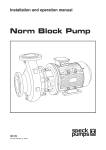
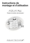
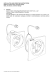
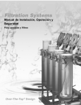
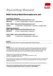
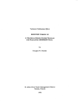
Installation and operation manual BADU Block ® 04/09 VG 766.1330.050 2' 04/ 09 D / F / GB - BA 1. General information GB CAUTION Speck Pumpen Verkaufsgesellschaft GmbH, Neunkirchen am Sand BADU Block Series Country of origin: Federal Republic of Germany This Speck pump has been developed according to the latest technical standards, manufactured with great care and is subject to continuous quality control. The present operation manual should provide an easy introduction to the pump and the range of possible applications for which it is intended. The operation manual contains important information for the safe, proper and efficient operation of the pump. These instructions must be adhered to in order to ensure the reliability and longevity of the pump as well as to avoid danger. Local regulations are not considered in this Operation Manual. The responsibility for these – and also for their observance by installation personnel – lies with the user alone. The operation manual does not account for locally applicable provisions, compliance with which is the responsibility of the user – also for the installation personnel involved. This unit may not be operated above the values specified in the technical documentation or any other instructions contained in the operation manual or contractual documentation regarding the pumped fluid, the pumped volume, speed, density pressure and temperature as well as motor power. If necessary contact the manufacturer. The nameplate identifies the series/size, the most important operating data and the identification number. Please always quote this number for any queries, reordering and in particular when ordering spare parts. Should any additional information or details be required, such as in the event of damage, please contact the nearest Speck customer care facility. 1.1 Certificates of conformity, test symbols and similar The CE symbol is attached to the pump. The certificate of conformity is included as an annex in the operation manual. 1.2 Noise level The noise level is very dependent on the pipes connected to the pump. The stated noise level is only applicable to the pump on its own. Refer to the technical data sheet in the annex (if available) for the noise level. If there is no value given for the noise level, it is below 75 dBA. 2. Safety This Operation Manual contains basic instructions, which must be observed during mounting, operation and maintenance. Therefore the Operation Manual should be carefully read before installation and startup by the person in charge of the installation as well as by all other technical personnel/operators and should at all times be available at the installation site. It is important that not only all general safety measures appearing under the above heading “Safety” should be adhered to but also all other, specialized safety instructions appearing under the other headings, e.g. for private use. 2.1 Symbols for Safety Instructions in the Operation Manual All safety warnings contained in the Operation Manual which, when ignored, may constitute danger for humans, are specially marked with general danger symbols: Safety symbol according to ISO 7000 - 04324 In case of electrical hazards they are specially marked with: Safety symbol according to IEC 417 - 5036 For safety warnings which, when ignored may constitute a hazard for the machine and its functions as well as for the surrounding, the word CAUTION is added. Symbols directly attached to the machine like e.g. - arrow denoting the direction of rotation - symbol for fluid connections must be heeded and kept fully legible at all times. 2.2 Personnel Qualification and Training All personnel for the operation, maintenance, inspection and installation must be fully qualified to perform that type of job. Responsibility, competence and the supervision of such personnel must be strictly regulated by the user. Should the available personnel be lacking the necessary qualification, they must be trained and instructed accordingly. If necessary, the operator may require the manufacturer/supplier to provide such training. Furthermore the operator/user must make sure that the personnel fully understands the contents of the Operation Instructions. 2.3 Dangers of Ignoring the Safety Symbols Ignoring the safety directions and symbols may cause danger to humans as well as to the environment and the machine itself. Non-observance of the safety instructions may void any warranties. Non-observance of safety directions and symbols may for example entail the following: - Failure of important functions of the machine/plant - Failure of prescribed methods for maintenance and repair - Endangerment of persons by electrical, mechanical and chemical effects - Danger to the environment because of leakage of hazardous material - Danger of damage to equipment and buildings 2 2.4 Safety-oriented Operation The safety directions contained in the Operation Instructions, existing national regulations for the prevention of accidents as well as internal working-, operational- and safety-regulations of the operator/user must be observed at all times. 2.5 General Safety Directions for the Operator / User - If hot or cold machine parts cause a danger, such parts must be protected by the operator/user against contact with personnel. and that it does not slide off the transport hanger. It is not permitted to hang the rope on the free end of the pump shaft or the eye bolt of the motor. The transport eye bolts on the motor are only approved for transporting the motor itself and not for the complete pump. If the pump/unit slides off the transport hanger this may cause physical injury or damage to property!! - Protective covers for moving parts (e.g. coupling) must not be removed when the machine is running. Leakages (e.g. at the shaft seal) of hazardous pumping media (e.g. explosive, toxic, hot liquids) must be disposed of without causing any danger for personnel and the environment. All government regulations must be observed at all times. - Any danger to persons etc. by electrical energy must be excluded. For details see e.g. regulations of VDE and the local utilities. 2.6 Safety Directions for Maintenance, Inspection and Assembly Work It is the user’s responsibility to make sure that all maintenance, inspection and assembly work is performed exclusively by authorized and qualified experts sufficiently informed through careful perusal of the Operating Instructions. The pump must be at ambient temperature, depressurized and emptied. Basically, all work on the machine is to be performed while the machine is not in operation. The sequence for shutting the machine down described in the Operating Instructions must be strictly observed. Pumps or pump units handling hazardous liquids must be decontaminated. Immediately upon completion of the work, all safety and protective equipment must be restored and activated. Before restarting the machine, all points contained in chapter “Initial Start-up” must be observed. 2.7 Unauthorized Changes and Manufacturing of Spare Parts Any conversion or changes of the machine may only be undertaken after consulting the manufacturer. Original spare parts and accessories authorized by the manufacturer guarantee operational safety. Using non-authorized parts may void any liability on the part of the manufacturer in case of consequential damage. 2.8 Unauthorized Operation The operational safety of the machine delivered is only guaranteed if the machine is used in accordance with the directions contained in the subsequent sections of the Operating Instructions. Limits stated in the data sheets may not be exceeded under any circumstances. 3. Transport, temporary storage 3.1 Transporting The unit must be transported correctly. It must be ensured that the unit is transported in a vertical position 3 VD 61.007 If the pump is transported without the motor, shaft 210 must be locked in position, 1. Press the cover panels 68-3 lightly together and remove them through the windows of the lantern bracket 341. 2. Pull the lock washer 931 into the wellnut and secure with the hexagon head screws 901.3. VD 60.016 3.2 Temporary storage (internal storage)/rust-proofing In case of temporary storage, only the components made from low alloy materials in contact with fluids (e.g. cast iron JL 1040), need to be rust-proofed. Commercially-available preserving substances can be used for this. For application/removal follow the specific instructions of the manufacturer. The procedure is described in Section 6.3. The unit/pump should be stored in a dry room with, as far as possible, constant humidity. For outside storage it is essential that the unit and the packing case are protected by a watertight cover in order to avoid contact with moisture. 4.3 CAUTION Protect stored goods against moisture, dirt, pests and unauthorized entry! All of the assembled components of the unit are enclosed and must only be opened when required for installation. All uncoated parts and surfaces of the pump are oiled or greased for rust protection (silicone-free oil or grease). Table of materials Version 05 12 Casing parts Tin bronze CC480K-GS Cast iron EN-JL 1040 Impeller Tin bronze CC480K-GS Tin bronze CC480K-GS Mechanical seal SiC/SiC/HNBR Carbon /SiC/EPDM on request SiC/SiC/HNBR Split ring CC495-GS CC495-GS Pump shaft 1.4571 X6 Cr Ni Mo Ti 17-12-2 1.4571 X6 Cr Ni Mo Ti 17-12-2 Shaft protection bush 1.4571 X6 Cr Ni Mo Ti 17-12-2 1.4571 X6 Cr Ni Mo Ti 17-12-2 Lantern bracket Cast iron EN-JL 1040 Cast iron EN-JL 1040 Pre-filter housing Cast iron EN-JL 1040 enamelled internally Cast iron EN-JL 1040 enamelled internally Suction filter (1.4571) X6 Cr Ni Mo Ti 17-12-2 1.4571) X6 Cr Ni Mo Ti 17-12-2 Filter cover Tin bronze CC480K-GS PA6.6 GF30* Tin bronze CC480K-GS PA6.6 GF30* VD 61.002 4. Product description and accessories 4.1 General description BADU Block centrifugal pumps are non self-priming, single-stage, spiral-casing pumps in a vertical block construction. A block pump and pre-filter housing are flange-connected to make a block unit. The compact construction provides high circulation performance with minimum space requirement. The back-pullout design allows the drive unit to be replaced without disconnecting the pipework for ease of assembly or disassembly. Due to the low speed, the pumps operate with little noise and minimum wear. 4.2 Constructional design Construction: Spiral pumps, single-stage with power rating according to EN 733. Shaft fitted with a replaceable shaft sleeve in the area of the shaft seal. The spiral casing and impeller are fitted with replaceable split rings. Flanged pump and motor are close-coupled to form a block unit with norm motor. The pump shaft is rigidly connected to the motor shaft. Shaft seal: Mechanical seal in accordance with EN 12 756. Drive: Electric motor Protection against accidental contact: Cover plates on the lantern bracket in accordance with EN 294. Circulation pipes and ventilation ball valve made from stainless steel and braided PVC hose. * * only for types: 32/160, 32/200, 32/250, 40/160, 40/200, 40/250, 50/160, 50/200, 50/250, 50/315, 65/160, 65/200, 65/250, 65/315, All rights reserved to make changes! 5. 5.1 Erection / installation Checks prior to erection The structural layout must be prepared in accordance with the dimension and assembly drawings. The foundations should be of sufficient concrete strength (min. class X0) according to DIN 1045. The concrete for the foundations must be set before the unit is erected on it. The surface must be horizontal and smooth. 5.1.1 Substratum, foundations, wall The foundations must be prepared in such a way that the pump or the complete unit can be safely erected and is free of stress. Stresses can lead to premature wear on the pump. Make sure that the foundations do not transfer vibrations. 5.1.2 Space requirements for operation and maintenance The pump unit must be installed in such a way that it is possible to exchange parts or even the complete unit. Heavy units must be equipped with appropriate facilities for fastening and supporting lifting tools and other devices. Suitable access routes must be provided for delivery and removal. 4 5.2 5.3 Erection of the unit During erection on the foundations, the unit must be aligned to the pressure connections using a spirit level. The spiral casing and pressure cover take on the approximate temperature of the pumped fluid. The pressure cover and lantern bracket must not be insulated. Appropriate security measures must be taken to avoid burns. Connecting the piping CAUTION Under no circumstances may the pump be used as an anchor point for the pipes. The piping system must not exert forces or torques (e.g. from torsion, thermal expansion) on the pump. The suction pipe must be fitted with an upward incline to the pump, the supply with a downward incline. The pipes must be supported directly in front of the pump and have stress-free connections. For short pipes, the nominal diameter must be at least the equivalent of the pump connections. For long pipes, the most economic nominal diameter should be determined separately in each case. Adaptor pieces for larger nominal diameters should be designed with an enlargement angle of approx. 8°, in order to avoid increased pressure losses. Depending on the type of installation and of the pump, it is recommended to fit non-return valves and shut-off valves. Suitable measures must be taken to compensate for the thermal expansion of the pipes, in order not to load the pump beyond the permitted pipe forces and pipe torques. If the pipe forces are exceeded, it is possible, for example, that leakage may occur on the pump, leading to the escape of pumped fluid. Danger to life from hot pumped medium! The flange covers on the suction and pressure connections must be removed before installation in the piping. Before any new installation is commissioned, the tanks, pipes and connections must be thoroughly cleaned, rinsed and air purged. Weld beads, scale and other contaminants often come loose only after an extended period of time 5.3.1 Supplementary connections The dimensions and position of the supplementary connection (draining) required for the pump is defined in the installation drawing or pipe layout diagram. 5.3.2 Dimensioning of the pipes In order to avoid friction losses in the pipes as far as possible, the maximum operating flow-rates in the suction or supply lines should be 1.5 m/s and in the pressure lines 2.5 m/s Pipe layouts and fluid quantities must be configured in accordance with the standards for piping to prevent the pump from sucking in air. Dry running of the pump can cause considerable damage to the pump and seals. 5 5.3.3 Measuring point schematic Pressure measurements on centrifugal pumps are carried out according to ISO 2548 “standardized experimental arrangements” (sketch 1, page 43). However, it should be ensured that the flow rate in the measuring pipes is not substantially higher than the stated values in Section 5.3.2. For flow rates higher than the values stated in Section 5.3.2, adaptor pieces must be fitted to the pressure and/or suction flanges (sketch 2, page 43). In order to ensure that reliable measurements are obtained at the plant, the pressure measurement should be made taking into account the flow rates according to Section 5.3.2 and the corresponding sketch. Pipe elbows, valves, adaptor pieces, etc. can falsify the measurement values and, therefore, must not be located too close to the pressure-measurement drill holes. The set-up for flow-rate measurement must be in accordance with the provisions of the manufacturer of the specific measuring equipment. Sketch 1 Sketch 2 VD 61.008 5.4 Electrical conection Electrical connection may only be carried out by a qualified electrical technician. Compliance with the relevant DIN VDE 0100 and explosive atmosphere 0165 regulations is required. Check the available mains voltage against the data on the motor rating plate and select the appropriate connection. In making the connection, the technical connection provisions of the local power supply company must be observed. The use of a motor protection device is strongly recommended. 5.4.1 Motor connection The direction of rotation of the three-phase AC motor is strictly clockwise in accordance with DIN VDE 0530 Part 8 (viewed from the motor stub shaft). The direction of rotation of the pump is anti-clockwise (viewed from the suction flange). In order to convert the motor to the direction of rotation of the pump it should be connected as shown in Fig. 5.4-1 or Fig. 5.4-2. Δ connection (low voltage) Fig. 5.4-1 Connection diagram for AC motors Δ connection 6 Y connection (high voltage) 6.1.1 Shaft seal Shaft seal (see 7.4.4 and 7.5.2) 6.1.2 Filling and checking the pump The pump and the supply line must be de-aerated and filled with pumping fluid before it is started up. The non-return valve in the suction line must be fully open. CAUTION VD 25.226 Fig. 5.4-2:Connection diagram for AC motors Y connection If required, connect the PTC thermistor according to DIN 44081/44082 with downstream trip device as per Fig. 5.4-3. Running the pump without fluid will cause increased wear and must be avoided! 6.1.3 Final check It must be possible to easily turn the shaft by hand. Check all connections for correctness and function. 6.1.4 Protection against accidental contact According to accident prevention regulations the pump may only be operated if it has protection against accidental contact. 6.1.5 Switching on Only switch the unit on with the shut-off valve on the pressure side closed. This should be slowly opened and adjusted to the operating point only once it has reached full speed. CAUTION Fig. 5.4-3 Connection diagram for PTC thermistor 5.4.2 Timer relay setting For AC motors connected in star-delta circuit must be ensured that the switchover points between star and delta rapidly succeed each other in very short intervals. Long switchover times will damage the pump. For star-delta circuits set the timer relay to <3 s. 5.4.3 Checking the direction of rotation The direction of rotation of the motor must be the same as the direction of rotation of the arrow on the spiral casing (clockwise as viewed from the motor side). Check by switching the motor on and then immediately off again. Checking the direction of rotation should only be carried out with the pump and pipes primed. Important components can be destroyed if the pump is run dry. In case of the wrong direction of rotation, reverse any two phases L1, L2 or L3 of the mains supply leads in the motor terminal box. After reaching operating temperature and/or in the event of leaks, tighten the hexagonal nut 920.2 or .3 or .4 with the unit switched off. 6.1.6 Switching off Close the shut-off valve in the pressure line. If a non-return valve is installed in the pressure line, the shut-off valve can remain open as long as there is back pressure. The shut-off valve in the supply Iine must not be closed when the pump is switched off. Switch off the motor. Make sure that it coasts quietly to a stop. Depending on the installation, the pump – with the heat source switched off – should coast for long enough to reduce the temperature of the pumped fluid far enough that an accumulation of heat inside the pump is avoided. For a long standstill, close the shut-off valve in the supply line. Close the supplementary connections. The pump should be emptied in case of a long standstill and to protect it against frost. 6.2 Operating range limits 6.2.1 Temperature of the pumped fluid CAUTION 6. 6.1 Start-up / switching off Initial start-up CAUTION Before starting the pump ensure that: - the unit is connected electrically with all of the protective devices in accordance with regulations. - the pump is filled with pumping fluid. - the direction of rotation has been checked. - all supplementary connections are made. 7 Do not operate the pump at tempertures higher than those specified in the data sheet or on the rating plate. 6.2.2 Switching frequency In order to avoid large temperature increases in the motor and excessive loading of the pump, motor, seals and bearings, the following number of switching cycles per hour (hr) must not be exceeded. BADU Block 15 switching cycles per hour. 6.2.3 Minimum volume If the type of installation includes the possibility of operating against a closed shut-off valve on the discharge side, a minimum pumping volume of t -30 to + 70 °C ≈ 15 % of Qopt. must be provided during this time. 6.2.4 Density of the pumped fluid The power consumption of the pump changes in proportion to the density of the pumped fluid. In order to avoid overloading the motor and pump, the density must be consistent with the order data. 6.3 Out-of-operation/storage/rust-proofing Every pump is carefully assembled before it leaves the factory. If start-up is to be delayed for any length of time after delivery, it is recommended to store the pump as described below. 6.3.1 Storing new pumps - New pumps are packed ready for storing in the factory. Protection appropriate for internal storage for a maximum of 12 months. - Store the pump in a dry location. 6.3.2 Procedures for an extended non-operational period 1. The pump remains installed and has its functions checked periodically In order to ensure a constant operational readiness and to avoid the build-up of deposits in the internal areas of the pump and the areas immediately next to the pump supply, during extended non-operational periods the pump should be functionally tested for a brief time (approx. 5 minutes) in a period every 1-3 months. Before starting the procedure, the pump must be supplied with a sufficient amount of fluid. 2. The pump is removed and put into storage Before putting the pump into storage carry out the checks according to 7.1 to 7.4. Then proceed with rust-proofing: - spray the inside of the pump casing with preserving substance, in particular the area around the impeller gap. Spray the preserving agent through the suction and discharge connections. It is recommended to close off the connections (e.g. with plastic caps or similar). 6.4 Restart after storage Before restarting the pump, carry out the check and maintenance procedures according to 7.1 and 7.2. In addition, the points listed in the sections initial start-up (6.1) and operational range limits (6.2) must be observed when starting to use the pump again. Immediately after completion of this work, all of the safety and protection equipment must be connected properly and functionally tested. 7. 7.1 Maintenance / inspection General information The user is responsible for ensuring that all maintenance, inspection and assembly work is carried out by qualified and authorized personnel who have sufficiently informed themselves by thoroughly studying the operation manual. By preparing a maintenance plan, expensive repairs can be avoided and fault-free and reliable operation of the pump can be obtained with minimum maintenance effort. No work must be carried out without first disconnecting the equipment electrically. To avoid any danger to life, the pump unit must be protected against accidental switch-on. Pumps which operate with fluids hazardous to health must be decontaminated. Care is required when draining the fluid to avoid any risk to personnel and the environment. Legal regulations must be complied with to avoid danger to life! 7.2 Maintenance / inspection 7.2.1 Monitoring CAUTION The pump must always run quietly and without vibrations. Dry-running the pump must be avoided. In order to avoid heating the pumped fluid, the pump must not be operated for long periods of time against a closed shut-off valve. Maximum permissible ambient temperature 40 °C. The storage temperature may be up to 50 °C above ambient temperature. However, it must not exceed +90 °C (measured externally on the motor casing). For the required mimimum volume see 6.2.3. The shut-off valve in the supply line must not be closed when the pump is in operation. A functioning mechanical seal must have no, or only a small amount of, visible leakage losses (vaporous). It is maintenance-free. Installed reserve pumps must be operated at least once weekly by rapid, sequential on and off switching, in order to ensure the constant operational readiness. The function of the supplementary connections must be monitored. 7.2.1.1Prefilter housing / suction filter CAUTION The suction filter in the prefilter housing must be cleaned periodically. If the suction filter is contaminated, the flow volume capacity of the pump is reduced and there is insufficient filtration. Contamination of the suction filter can be identified by a change of, or an increase in, the displayed value of the suction-side manovacuumeter (vacuum pressure gauge). 7.2.1.2Cleaning the suction filter - Switch off the pump and take precautions to prevent it being switched on again. - Only carry out the work with the electric power switched off. 8 - Close the shut-off valves in the supply, suction and pressure lines. - Empty the prefilter housing using the drain plug (903.3). - Unscrew the star handle (925) and remove the filter cover (160). - Take out the suction filter (143), clean and put it back in its place. - Screw on the filter cover (160) uniformly using the star handle (925) evenly. - Open the shut-off valves. CAUTION - De-aerate the pump unit using the ball valve (743). 7.2.2 Lubrication and lubricants 7.2.2.1 Lubrication The roller bearings in the IEC motor are lubricated with grease. The intervals, quality and quantity are given below. 7.2.2.2 Grease quality / grease replacement The bearings are provided with high-quality, lithiumsoap grease. The filling will last for 15,000 operating hours or 2 years under normal operating conditions. In the case of unfavourable operating conditions, e.g. high ambient temperature, high humidity, dusty air, aggressive industrial atmosphere, etc. the bearings should be checked correspondingly earlier and, if necessary, cleaned. For this purpose, a grease containing lithium soap should be used, it should be free of resin and acid, must not become brittle and should provide rust protection. The grease should have a penetration value between 2 and 3, corresponding to a walk penetration of 220 to 295 mm/10. The drop point should not be below 175 °C. The cavities in the bearings may only be approximately half filled with grease. If necessary, the bearings can also be filled with greases having different soap bases. As greases containing different soap bases may not be combined, the cavities must first be washed clean. The necessary subsequent lubrication periods must then be adjusted to match these greases. CAUTION In regard to disposal, the general legal requirements in force must be observed. Sealed bearings with permanent lubrication (2 RSbearing or 2 Z bearing) cannot be washed clean and refilled with grease. In this case the bearings must be renewed. Motors of model size 180 upwards are provided with relubrication devices and flange lubrication nipples in accordance with DIN 3404. 7.3 9 Emptying / disposal If the pump is used to convey fluids hazardous to health, care is required when emptying the pump in order to avoid risk to personnel or the environment. Legal regulations must be observed. Whenever necessary, wear protective clothing and protective masks! 7.4 Disassembly Before starting the disassembly, make sure that the pump cannot be switched on again. The shut-off valves in the suction and discharge lines must be closed. The pump must be at ambient temperature, zero pressure and must be empty. Disassembly and assembly may only be carried out with reference to the exploded diagrams. 7.4.1 Basic regulations / instructions Repair and maintenance work on the pump may only be carried out by specially trained personnel and only using original spare parts (see 2.7). The safety provisions according to 7.1 must be observed. When working on the motor, follow the instructions and provisions of the motor manufacturer. Disassembly and reassembly must be carried out in the sequence shown in the exploded diagrams on pages 52 to 54. In case of damage, please contact our nearest customer services facility. See the attached list of addresses for our customer services locations. 7.4.2 Preparatory work for disassembly 1 Disconnect the electrical power supply. 2 Disassembly of the complete unit: 2.1 Disconnect the motor leads 2.2 Disconnect the discharge and suction connections from the pipes. 2.3 Disconnect the fixing bolts attaching the filter housing to the foundations. 2.4 Pull out the complete unit from the piping. 3 The pump casing remains in the piping during disassembly. 3.1 Disconnect the motor leads. 3.2 Unscrew the hexagonal nut 920.2 or. 920.4. 3.3 Pull out the installation set and motor from the pump casing. 4. The pump remains in the piping, disassembly of the motor 4.1 Disconnect the motor leads. 4.2 Press the cover panels 68-3 lightly together and remove them from the windows of the lantern bracket 341. 4.3 Unscrew the hexagonal nuts 920.5. 4.4 Unscrew the hexagonal bolts 901.3.. 4.5 Place both locking plates 931 on the shaft keyseat 210. 4.6 Tighten hexagonal bolts 901.3. 4.7 Detach the motor. After a long period of operation individual parts may possibly be difficult to detach from the shaft. In this case one of the well-known rust solvents can be used or, possibly, a suitable extractor tool. Under no circumstances force should be used. 7.4.3 Pump Disassembly of the pump must be carried out in the sequence shown in the exploded diagrams on pages 52 to 54. 7.4.4 Mechanical Seal In order to change the mechanical seal, it is necessary to disassemble the pump. After the impeller 230 has been removed, the mechanical seal 433 can be pulled from the shaft by hand. Clean the shaft sleeve 523 before assembly and, if required, remove any scores or scratches with emery cloth. If scoring or pitting is still visible, replace the shaft sleeve, clean the counter-ring seat. 7.5 Reassembly 7.5.1 Pump The assembly of the pump must be carried out in accordance with the machinery regulations in force. Before starting the assembly, the mating areas of individual parts must be brushed with graphite or a similar substance. This applies equally to bolt connections. Check O-rings for damage and replace where necessary. Gaskets must be replaced as a matter of course. Always replace them with seals of the same thickness. As a general practice, gaskets made from asbestosfree materials or graphite must be assembled with out the use of lubricants. Assembly aids should be avoided if at all possible. However, if it is necessary, use a commercially-available contact adhesive (e.g. Pattex) or HY-LOMAR or Epple 33 sealant. The sealant must be applied at selected points as a thin film. Cyanoacrylate adhesive (instant glue) must not be used. If the sealing area between the impeller neck and the split ring is worn, the split ring 502.1 and, where fitted, 502.2 must be renewed. Play in the gap: new 0.3 mm on Ø maximum permissible extension to 0.9 mm on Ø The assembly is carried out in the reverse sequence to that used for disassembly. It is essential to maintain the correct sequence of individual parts. 7.5.2 Mechanical Seal The insertion is carried out in the reverse sequence to that used for removal. The basic rules for assembly of a mechanical seal are as follows: Maximum care, extreme cleanliness. Only remove the contact protection from the slide faces just before starting the assembly. Damage to sealing surfaces and the O-rings must be avoided. Clean the shaft and the counter-ring seat in the pressure cover and carefully remove deposits. During assembly of the seal, the friction forces of the shaft sleeve 523 can be reduced by wetting the surfaces with water. CAUTION Elastomers made from EP rubber must never come into contact with oil or grease. Use water to help with the assembly. Only hand or finger pressure should be used when pressing the counter-ring into the pressure cover 163. Ensure even pressure distribution. 7.5.3 Assembly of the motor The motor is mounted in the reverse sequence to that used for dismantling. During installation and before start-up, particular care must be taken to pull the locking plates 931 out of the shaft keyseat and to secure them with the hexagonal bolts 901.3 CAUTION When mounting the shaft 210 to the motor stub shaft, ensure that the keyseat on the motor shaft end and the slot of shaft 210 are congruent and aligned opposite to the slot of clamping ring 515. Section A-A VW 60.006 Fig. 7.5-1 Shaft assembly Part No. Part name 210 515 901.3 914.1 931 Shaft Clamping ring Hexagonal bolt Allen head screw Locking plate 10 7.5.4 Screw tightening torques VW 61.003 Fig. 7.5-2 Bolt tightening points for pump unit Item A B C D 1) Thread size [mm] M 10 M 12 M 16 M 20 M 12 x 1,5 M 20 x 1,5 M 30 x 1,5 M8 M 10 M 12 M 16 M6 M8 Tightening torque 1) MA [Nm] 40 55 90 140 25 85 140 15 30 45 80 10 25 Refers to non-lubricated threads A = Bolt connections on the casing parts B = Impeller nut C = Bolt connections lantern bracket/motor D = Bolt clamp ring/stub shaft 11 7.6 Ordering spare parts The following information from the rating plate must be included with each order for spare parts, e.g.: Type BADU Block 50/160 Serial No.: Model: Year of manufacture: 2002 or the spiral housing, e.g.: 50/160 7.6.1 Recommended spares holding for two-year continuous operation according to DIN 24 296 Part No. Part name Quantity of pumps (including reserve pumps) 2 3 4 5 6 and 7 8 and 9 10 or more Quantity of spare parts 210 Shaft 1 1 1 2 2 2 20 % 230 Impeller (including split ring 502.2) 1 1 1 2 2 2 20 % 230.1/.2 Impeller (set) 1 1 1 2 2 2 20 % 400.1/.2 Gaskets (set) 4 6 8 8 9 12 150 % 412.3 O-ring 2 3 4 4 4 5 100 % 433 Mechanical seal 1 1 2 2 2 3 25 % 502.1 Split ring 2 2 2 3 3 4 50 % 523 Shaft sleeve 2 2 2 3 3 4 50 % 12 Faults / causes and remedies too little pumped volume from the pump drive equipment overloaded motor protection switch is de-energised increased bearing temperature leakage at the pump excessive leakage at the shaft seal the pump is not running smoothly unacceptable temperature increase in the pump 8. Remedy 1) set new operating point check installation for contamination de-aerate or top up Cause Pump operates against too much pressure Back pressure too high Pump or piping not fully de-aerated or not topped up Supply line or impeller blocked Formation of air pocket in piping change piping insert an air-bleed valve correct the fluid level open the shut-off valve in the supply line change the supply line if necessary, if the resistances in the supply line are too large, check the installed filter/suction openings reverse two phases of the power supply renew worn parts adjust the operating point Incorrect direction of rotation Wear on internal parts Pump back-pressure is smaller than was stated in the purchase order Higher density or higher viscosity of the pumped fluid than was stated in the purchase order Defective seal Shaft seal worn Formation of scores or roughness on the shaft sleeve Pump runs irregularly Pump is twisted Increased axial stroke 2) Too little, too much, or unsuitable lubricant Running on 2 phases Suction height too large/NPSHplant (infeed too small) Rotor out of balance Damaged bearing Pumped volume is too low Motor protection switch is not set correctly The transport safety devices have not been removed from the keyseat 1) 2) remove deposits in the pump or piping 2) renew the seal between the spiral casing and pressure cover renew shaft seal renew the shaft sleeve renew the shaft seal correct the suction conditions increase the pressure on the pump suction connections check pipe connections and pump fixings if necessary reduce the spacing of the pipe clamps, affix the piping using vibration-reducing material clean the impeller relief bores replace the split ring increase, reduce or replace the lubricant replace blown fuse check the connection of the electrical leads clean the impeller re-balance the impeller renew increase the minimum pumped volume check the setting replace the motor protection switch remove The pump must be depressurized before correcting faults on parts which are under pressure Enquiry required 13 The pages which follow contain the spare parts drawings and spare parts lists. Please turn the page! 14 9. Related documents Spare-parts drawing BADU Block Model with clamped pressure cover 801 901.3 °˜ 920.5 163 ˜ 400.1 902.5 68-3 400.2 920.4 ˜˜ 523 914.1 502.2 "˜ 230 210 550.1 701 930 502.1 940 920.1 902.3 102 920.6 903.1 903.1 1.4 902.4 400 903.4 902.10 ˜ 124 925 412.9 1.3 160 903.3 Drawing No. VW61.002 15 Spare parts list BADU Block Model with clamped pressure cover Valid for: BADU Block 32/160, 40/160, 50/160, 65/160, 80/160, 80/200, 100/160, 100/200, 125/315, 150/315 VDMA-Nr. Description 102 Spiral casing 124 Pre-filter housing 143 Suction filter 160 Cover 163 Pressure coverl 210 Shaft 230 Impeller 341 Lantern bracket 400 Gasket 400.1 Gasket 400.2 Gasket 411.3 Sealing ring 411.4 Sealing ring 412.9 Round sealing ring 433 Mechanical Seal 502.1 Split ring 502.2 Split ring 515 Clamping ring 523 Shaft sleeve 550.1 Disc 68-3 Cover plate 701 Circulation pipe 743 Air-bleed valve 801 Flanged motor 901.3 Hexagonal bolt 902.3 Stud bolt 902.4 Stud bolt 902.5 Stud bolt 902.10 Stud bolt 903.1 Locking screw 903.3 Locking screw 903.4 Locking screw 914.1 Allen head bolt 920.1 Hexagonal nut 920.4 Hexagonal nut 920.5 Hexagonal nut 920.6 Hexagonal nut 925 Star handle 930 Spring washer 931 Locking plate 940 Shaft key When ordering spare parts, please include the following information: the type of pump, the serial number and the article numbers of the parts. VW61.002-01 16 Spare parts drawing BADU Block Model with screwed-on pressure cover 801 901.3 °˜ 920.5 920.2 902.2 163 ˜ 400.1 902.5 68-3 400.2 920.4 ˜˜ 523 914.1 502.2 "˜ 230 210 550.1 701 930 502.1 940 920.1 902.1 102 920.6 903.1 903.1 1.4 902.4 400 903.4 902.10 ˜ 124 925 412.9 1.3 160 903.3 Drawing No. VW61.001 17 Spare parts list BADU Block Model with screwed-on pressure cover Valid for: BADU Block 32/200, 32/250, 40/200, 40/250, 50/200, 50/250, 50/315, 65/200, 65/250, 65/315, 80/250, 80/315, 100/250, 100/315, 125/250, 150/250 VDMA-Nr. 102 124 143 160 163 Pressure 210 230 341 400 400.1 400.2 411.3 411.4 412.9 433 502.1 502.2 515 523 550.1 68-3 701 743 801 901.3 902.1 902.2 902.4 902.5 902.10 903.1 903.3 903.4 914.1 920.1 920.2 920.4 920.5 920.6 925 930 931 940 Description Spiral casing Pre-filter housing Suction filter Cover cover Shaft Impeller Lantern bracket Gasket Gasket Gasket Sealing ring Sealing ring Round sealing ring Mechanical Seal Split ring Split ring Clamping ring Shaft sleeve Disc Cover plate Circulation pipe Air-bleed valve Flanged motor Hexagonal bolt Stud bolt Stud bolt Stud bolt Stud bolt Stud bolt Locking screw Locking screw Locking screw Allen head bolt Hexagonal nut Hexagonal nut Hexagonal nut Hexagonal nut Hexagonal nut Star handle Spring washer Locking plate Shaft key When ordering spare parts, please include the following information: the type of pump, the serial number and the article numbers of the parts. VW61.001-01 18 V E R K A U F S G E S E L L S C H A F T GmbH EG-Konformitätserklärung Déclaration CE de conformité / EC declaration of conformity / Dichiarazione CE di conformità / EG-verklaring van overeenstemming / EU-yhtäpitävyysilmoitus / Declaracion de conformidad im Sinne der EG-Maschinenrichtlinie 89/392/EWG, Anhang II A conformément à la directive CE relative aux machines 89/392/CEE , Annex II A / as defined by machinery directive 89/392/EEC Annexe II A / ai sensi della direttiva CE 89/392 relativa a macchinari, Appendice II A / inzake richtlijn van de raad betreffende machines 89/392/EEG, bijlage II A / määriteltynä konedirektiivin 89/392/EEC liite ll mukaan / segun se define en la directriz para maquinas de la CE 89/392/CEE, Anexo II A Hiermit erklären wir, dass das Pumpenaggregat Par la présente, nous déclarons que le groupe moteur-pompe / Herewith we declare that the pump unit / Si dichiara, che la pompa / hiermede verklaren wij, dat het pompaggregaat / Täten ilmoitamme, että pumppulaite / Por la presente declaramos que la unidad de bomba: Type: Type: / Type: / Tipo: / Type: / Malli: / Tipo: Auftrags- Nr: N° d´ ordre: / Order no.: / Numero d´ordine: / Opdracht-Nr.: / Tilausnumero: / N° pedido: Baureihe Série: / Series: / Serie: / Serie: / Mallisarja:/ Serie: BADU Block folgenden einschlägigen Bestimmungen entspricht: correspond aux dispositions pertinentes suivantes: / complies with the following provisions applying to it: / è conforme alle s pertinenti: / in de door ons geleverde uitvoering voldoet aan de eisen van de in het vervolg genoemde bepalingen: / cumple las disposiciones pertinentes: / vastaa seuraavia asiaan kuuluvia määräyksiä: equenti disposizioni siguientes EG-Maschinenrichtlinie 98/37/EG CE-Directives européennes 98/37/CE: / EC-machinery directive 98/37/EC: / CE-Direttiva Macchine 98/37/CE: / EG-Machinerichtlijn EU-konedirektiivi 98/37/EU: / directiva europea de maquinaria 98/37 CE: 98/37/EG: / EMV-Richtlinie 89/336/EWG, i.d.F. 93/68/EEC Directives CE sur la compatibilité électromagnétique 89/336/CEE modifiées par 93/68/CEE: / EMC-Machinery directive 89/336/EEC, in succession 93/68/EEC / Direttiva di compatibilità elettromagnetica 89/336/CEE mod.93/68/CEE: / Richtlijn 89/336/EEG, gewijzigd door 93/68/ EEG: / Sähkömagneettinen yhteensopivuus (EMC) konedirektiivi 89/336/EEC, jota on muutettu direktiivillä 93/68/EEC: / directiva 89/336/CEE: / EG-Niederspannungsrichtlinie 2006/95/EG CE-Directives basse tension 2006/95/CE / EC-Low voltage directive 2006/95/EC / CE-Direttiva di bassa tensione 2006/95/CE / EG-l richtlijn 2006/95/EG / EU-pienjännitedirektiivi 2006/95/EU / directiva de baja tension 2006/95/CE aagspannings- EG-Richtlinie 2002/96/EG (WEEE) Directive 2002/96/CE (DEEE) / Directive 2002/96/EC (WEEE) / Direttiva UE 2002/96/EG (WEEE) / EG-Richtlijn 2002/96/EG (WEEE) / E U-direktiivi 2002/96/EC (WEEE) / CE-Directiva 2002/96/EG (tratamiento de residuos de componentes de aparatos eléctricos y electrónicos en desuso) EG-Richtlinie 2002/95/EG (RoHS) Directive 2002/95/CE (RoHS) / Directive 2002/95/EC (RoHS) / Direttiva UE 2002/95/EG (RoHS) / EG-Richtlijn 2002/95/EG (RoHS) / E U-direktiivi 2002/95/EC (RoHS) / CE-Directiva 2002/95/EG (limitación de utilización de determinados productos peligrosos en aparatos eléctricos y electrónicos) Angewendete harmonisierte Normen, insbesondere EN 60335-1 EN 60335-2 – Teil 41 D-91233 Neunkirchen a. Sand, Ort Fait à Place Localita Plaats Paikka Lugar 01.04.2009 Datum le date data Datum Päiväys Fecha i.V. F. Eisele (Technischer Leiter) (Directeur Technique) (Technical director) (Direttore tecnico) (Technisch directeur) (Teknillinen johtaja) (Director tecnico) Adresse / Adresse / Address / Indirizzo / Adres / Osoite / Direccion: Hauptstraße 1-3 D-91233 Neunkirchen a. Sand ppa. A. Herger (Produktmanager) (Chef de produits) (Product manager) (Responsabile prodotti) (Productmanager) (Tuotepäällikkö) (Jefe de producción) VG 766.1330.050 2' 04/ 09 D/F/GB - BA Normes harmonisées utilisées, notamment: / Applied harmonized standard in particular / Norme armonizzate applicate in particola re / Gebruikte geharmoniseerde normen, in het bijzondere / Käytettyjä harmonisoituja normeja, erityisesti / Normas armonizadas aplicadas, especialmente