1
®
Operating Instructions Servo Horizontal Axis SHA-340 without servo motor
5
Replacing the guide elements and drive elements
5.1 Changing the toothed belt of the slide
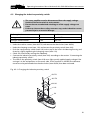
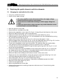
! Carry out a reference traverse.
! Switch off the supply voltage.
! The servo amplifier must be disconnected from the supply voltage.
Switch off the main switch or main contact.
! Ensure that no unauthorized switching-on of the supply voltage can
occur.
! Failure to observe these safety measures may result in death or severe
personal injuries or material damage.
!
!
!
!
!
!
!
!
!
!
!
!
!
!
!
!
!
!
!
Mark the position of the slide.
Remove devices attached to the slide.
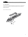
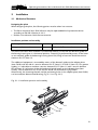
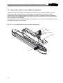
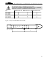
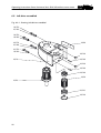
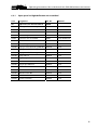
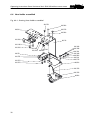
Remove the snapped-on covers (Item 150, Fig. 4.1-1) by pulling in the direction of the arrow.
Move the slide into the region of the removed covers.
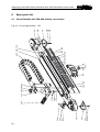
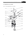
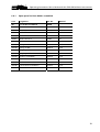
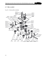
Undo screw (Item 20/170, Fig. 6.3-1) and remove cover (Item 20/60, Fig. 6.3-1).
Undo hexagon nut (Item 20/150, Fig. 6.3-1) and completely relax the toothed belt by turning
the camshaft (Item 20/30, Fig. 6.3-1).
Undo machine screws (Item 50/170, Fig. 6.5-1) and unscrew by approx. 5 mm.
Remove adapter plate (Item 50/40, Fig. 6.5-1) from the slide body (Item 50/10, Fig. 6.5-1) so that
the toothed belt can be removed from the clamps (Item 50/30, Fig. 6.5-1).
Fasten new toothed belt to the end of the old one. The adhesive tape must hold reliably,
since otherwise extensive dismantling of the servo horizontal axis is required.
Carefully draw the new toothed belt through the bearing housing (Item 130, Fig. 6.1-1) and
remove the old toothed belt.
Position the ends of the new toothed belt in the clamps (Item 50/30, Fig. 6.5-1) and fix with
the adapter plate (Item 50/40, Fig. 6.5-1) by tightening the machine screws (Item 50/170,
Fig. 6.5-1) (ensure vertical positioning of the toothed belt).
Move the slide to the marked position without rotation of the motor shaft.
Slightly tension the toothed belt by turning the eccentric shaft (Item 20/30, Fig. 6.3-1) and
secure by tightening the hexagon nut (Item 20/150, Fig. 6.3-1).
Snap covers (Item 150, Fig. 4.1-1) onto the bearing housing.
Set toothed belt pretension according to "Setting the toothed belt pretension (slide)".
Mount the cover (Item 20/60, Fig. 6.3-1).
Check the work performed.
Mount attached devices to the slide.
Perform offset correction according to operator software manual "Commissioning after
maintenance work".
21