1
Chapter 6
TROUBLESHOOTING
6.1 Before Proceeding with Troubleshooting
If any of the protective functions have been activated, first remove the cause. Then, after
checking that the all run commands are set to off, reset the alarm. Note that if the alarm is reset
while any run commands are set to on, the inverter may supply the power to the motor which may
cause the motor to rotate.
Injury may occur.
-
Even though the inverter has interrupted power to the motor, if the voltage is applied to the
main circuit power input terminals L1/R, L2/S and L3/T (L1/L and L2/N for single-phase
voltage input), voltage may be output to inverter output terminals U, V, and W.
- Some electric charge may remain in the DC link bus capacitor even after the power is turned
off. Therefore, it may take some time until the DC link bus voltage reaches a safe level.
Before touching the circuit, wait for at least five minutes after the power has been turned off
and check that the DC voltage between main circuit terminals P (+) and N (-) is less than +25
VDC using a multimeter.
Electric shock may occur.
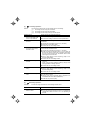
Follow the procedure below to solve problems.
(1) First, check that the inverter is correctly wired, referring to Chapter 2, Section 2.3.5 "Wiring for
Main Circuit Terminals and Grounding Terminals."
(2) Check whether an alarm code is displayed on the LED monitor.
If any problems persist after the above recovery procedure, contact your Fuji Electric representative.
6-1
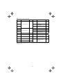
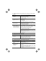
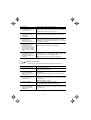
Quick reference table of alarm codes
Alarm code
Name
Refer to Alarm code
Name
Refer to
0h4
PTC thermistor for motor
protection
p.6-13
dbh
Overheat protection for
braking resistor
p.6-14
0c3
0l1
Electronic thermal overload
relay
p.6-14
0u1
0lu
Overload protection
p.6-15
er1
Memory error
p.6-15
er2
Remote keypad
communications error
p.6-16
0c1
0c2
0u2
Overcurrent protection
Overvoltage protection
p.6-9
p.6-10
0u3
lu
lin
Undervoltage protection
p.6-10
er3
CPU error
p.6-16
Input phase loss protection
p.6-11
er6
Operation protection
p.6-17
er8
RS-485 communications
error
p.6-17
erf
Data save error during
undervoltage
p.6-18
0pl
Output phase loss protection
p.6-12
0h1
Overheat protection for heat
sink
p.6-12
0h2
External alarm input
p.6-13
(Note) An under bar ( _ _ _ _ ) will be displayed when an undervoltage condition is detected and a run
command is present while the setting of F14 (Restart mode after momentary power failure (function
selection)) is not “0.”
6-2
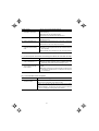
6.2 If No Alarm Code Appears on the LED Monitor
6.2.1
[1]
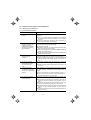
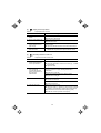
Motor is running abnormally
The motor does not rotate.
Possible Causes
What to Check and Suggested Measures
(1) No power supplied to the
inverter.
Check the input voltage, output voltage and interphase voltage
unbalance.
Turn on a molded case circuit breaker, an earth leakage
circuit breaker (with overcurrent protection) or a magnetic
contactor.
Check for voltage drop, phase loss, poor connections, or
poor contacts, and fix them if necessary.
(2) No forward/reverse
operation command was
inputted, or both the
commands were inputted
simultaneously (external
signal operation).
Check the input status of the forward/reverse command with
Menu #4 "I/O checking" using the keypad.
(3) No indication of rotation
direction (keypad
operation).
Check the input status of the forward/reverse rotation direction
command with Menu #4 "I/O checking" using the keypad.
(4) The inverter could not
accept any run commands
from the keypad since it
was in Programming
mode.
Check which operation mode the inverter is in, using the
keypad.
(5) A run command with
higher priority than the
one attempted was active,
and the run command was
stopped.
While referring to the block diagram of the drive command
generator*, check the higher priority run command with Menu
#2 "Data checking" and Menu #4 "I/O checking" using the
keypad.
Input a run command.
Set either the forward or reverse operation command to off if
both commands are being inputted.
Correct the assignment of commands FWD and REV to
function codes E98 and E99.
Connect the external circuit wires to control circuit terminals
[FWD] and [REV] correctly.
Input the rotation direction (F02 = 0), or select the keypad
operation with which the rotation direction is fixed (F02 = 2
or 3).
Shift the operation mode to Running mode and enter a run
command.
*Refer to the FRENIC-Mini User’s Manual (MEH446), Chapter 4.
Correct any incorrect function code data settings (e.g.,
cancel the higher priority run command).
(6) The reference frequency
was set below the starting
or stop frequency.
Check that a frequency command has been entered, with
Menu #4 "I/O checking" using the keypad.
Set the value of the frequency command to the same or
higher than that of the starting or stop frequency (F23 or
F25).
Reconsider the starting and stop frequencies (F23 and
F25), and if necessary, change them to lower values.
Inspect the frequency command devices, signal converters,
switches, or relay contacts. Replace any ones that are
faulty.
Connect the external circuit wires correctly to terminals [13],
[12], [11] and [C1].
6-3
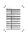
Possible Causes
What to Check and Suggested Measures
(7) A frequency command
with higher priority than
the one attempted was
active.
Check the higher priority run command with Menu #2 "Data
checking" and Menu #4 "I/O checking" using the keypad,
referring to the block diagram of the drive command generator.
*Refer the FRENIC-Mini User’s Manual (MEH446), Chapter 4.
Correct any incorrect function code data settings (e.g.
cancel the higher priority run command).
(8) The peak and bottom
frequencies for the
frequency limiters were
set incorrectly.
Check the data of function codes F15 (frequency limiter (high))
and F16 (frequency limiter (low)).
(9) The coast-to-stop
command was effective.
Check the data of function codes E01, E02, E03, E98 and E99
and the input signal status with Menu #4 "I/O checking" using
the keypad.
(10) Broken wire, incorrect
connection or poor contact
with the motor.
Check the cabling and wiring (Measure the output current).
(11) Overload
Measure the output current.
Change the settings of F15 and F16 to the correct ones.
Release the coast-to-stop command setting.
Repair the wires to the motor, or replace them.
Lighten the load.
Check that a mechanical brake is in effect.
Release the mechanical brake, if any.
(12) Torque generated by the
motor was insufficient.
Check that the motor starts running if the value of torque boost
(F09) is increased.
Increase the value of torque boost (F09) and try to run the
motor.
Check the data of function codes F04, F05, H50, and H51.
Change the V/f pattern to match the motor's characteristics.
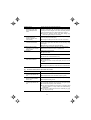
[2]
The motor rotates, but the speed does not increase.
Possible Causes
What to Check and Suggested Measures
(1) The maximum frequency
currently specified was too
low.
Check the data of function code F03 (Maximum frequency).
(2) The data of frequency
limiter currently specified
was too low.
Check the data of function code F15 (Frequency limiter (high)).
(3) The reference frequency
currently specified was too
low.
Check the signals for the frequency command from the control
circuit terminals with Menu #4 "I/O checking" using the keypad.
Readjust the data of the maximum frequency (F03).
Readjust the setting of F15.
Increase the frequency of the command.
If an external potentiometer for frequency command, signal
converter, switches, or relay contacts are malfunctioning,
replace them.
Connect the external circuit wires to terminals [13], [12],
[11], and [C1] correctly.
6-4
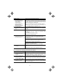
Possible Causes
What to Check and Suggested Measures
(4) A frequency command
with higher priority than
the one attempted (e.g.,
multi-frequency,
communications or
jogging operation, etc.)
was active and the
reference frequency was
set to too low a value.
Check the settings (data) of the relevant function codes and
what frequency commands are being received, through Menu
#1 "Data setting," Menu #2 "Data checking" and Menu #4 "I/O
checking," using the remote keypad and referring to the block
diagram of the frequency setting circuit.
(5) The acceleration/
deceleration time was too
long.
Check the data of function codes F07, F08, E10, E11 and H54.
(6) Overload
Measure the output current.
*Refer to the FRENIC-Mini User’s Manual (MEH446), Chapter 4.
Correct any incorrect function code data settings (e.g.
cancel higher priority run commands, etc.).
Change the acceleration/deceleration time to match the
load.
Lighten the load (e.g., operate the mechanical brake
correctly).
Check if mechanical brake is working.
Release the mechanical brake.
(7) The current limiting
operation did not increase
the output frequency.
Make sure that F43 (Current limiter (mode selection)) is set to
"2" and check the setting of F44 (Current limiter (level)).
Readjust the setting of F44, or disable the function of current
limiting in F43.
Decrease the value of torque boost (F09), then turn the power
off and back on again and check if the speed increases.
Adjust the value of the torque boost (F09).
Check the data of function codes F04, F05, H50, and H51 to
ensure that the V/f pattern is right.
Match the V/f pattern values with the motor ratings.
(8) Bias and gain set
incorrectly.
Check the data of function codes F18, C50, C32, C34, C37 and
C39.
Readjust the bias and gain to appropriate values.
[3]
The motor runs in the opposite direction to the command.
Possible Causes
What to Check and Suggested Measures
(1) Wiring has been
connected to the motor
incorrectly
Check the wiring to the motor.
(2) Incorrect connection and
settings for run commands
and rotation direction
command FWD and REV
Check the data of function codes E98 and E99 and the
connection to terminals [FWD] and [REV].
(3) The setting for the rotation
direction via keypad
operation is incorrect.
Check the data of function code F02 (Operation method).
Connect terminals U, V, and W of the inverter to the
respective U, V, and W terminals of the motor.
Correct the data of the function codes and the connection.
Change the data of function code F02 to 2 (forward rotation)
or 3 (reverse rotation).
6-5
[4]
If the speed variation and current vibration (such as hunting) occur at the constant
speed
Possible Causes
What to Check and Suggested Measures
(1) The frequency command
fluctuated.
Check the signals for the frequency command with Menu #4
"I/O checking" using the keypad.
Increase the filter constants (C33 and C38) for the
frequency command.
(2) The external frequency
command device was
used.
Check that there is no noise in the control signal wires from
external sources.
(3) The slip compensation
gain was too large.
Check that the motor vibration is absorbed if the slip
compensation (P09) is cancelled.
Isolate the control signal wires from the main circuit wires as
far as possible.
Use shielded or twisted wires for the control signal.
Readjust the slip compensation value (P09) or deactivate
slip compensation altogether.
(4) The vibration system
having low stiffness in a
load caused hunting or the
current is irregular due to
special motor constants.
Cancel the automatic control system (automatic torque boost,
slip compensation, energy saving operation, overload
prevention control, current limiting) and check that the motor
vibration is suppressed (F37, P09, H70, and F43).
Cancel the functions causing the vibration.
Readjust the data of the oscillation suppression gain (H80)
currently set to appropriate values.
Check that the motor vibration is suppressed if you decrease
the level of the motor sound (carrier frequency) (F26) or set the
motor sound (tone) to "0" (F27 = 0).
Decrease the carrier frequency (F26) or set the sound tone
to "0" (F27 = 0).
[5]
If grating sound can be heard from motor
Possible Causes
What to Check and Suggested Measures
(1) The carrier frequency was
set too low.
Check the data of function codes F26 (Motor sound (carrier
frequency)) and F27 (Motor sound (tone)).
Increase the carrier frequency (F26).
Readjust the setting of F27 to appropriate value.
[6]
The motor does not accelerate and decelerate at the set time.
Possible Causes
What to Check and Suggested Measures
(1) The inverter ran the motor
by S-curve or curvilinear
pattern.
Check the data of function code H07 (Acceleration/
deceleration pattern).
(2) The current limiting
prevented the output
frequency from
increasing.
Make sure that F43 (Current limiter (mode selection)) is set to
"2", and check that the setting of F44 (Current limiter (level)) is
reasonable.
Select the linear pattern (H07 = 0).
Readjust the setting of F44 to appropriate value, or disable
the function of current limiting in F43.
Increase the acceleration/deceleration time (F07, F08, E10,
and E11).
6-6
Possible Causes
What to Check and Suggested Measures
(3) The automatic
deceleration was active.
Check the data of function code H69 (Automatic deceleration
(mode selection)).
Consider the use of a braking resistor.
Increase the deceleration time (F08 and E11).
(4) Overload
Measure the output current.
(5) Torque generated by the
motor was insufficient.
Check that the motor starts running if the value of the torque
boost (F09) is increased.
(6) An external frequency
command device is being
used.
Check that there is no noise in the external signal wires.
Lighten the load.
Increase the value of the torque boost (F09).
[7]
Isolate the control signal wires from the main circuit wires as
far as possible.
Use shielded wire or twisted wire for the control signal wires.
Even if the power recovers after a momentary power failure, the motor does not restart.
Possible Causes
What to Check and Suggested Measures
(1) The setting of function
code F14 is either 0 or 1.
Check if an undervoltage trip occurs.
(2) The run command stayed
off even after power has
been restored.
Check the input signal with Menu #4 "I/O checking" using the
keypad.
[8]
Change the data of function code F14 (Restart mode after
momentary power failure (mode selection)) to 4 or 5.
Check the power recovery sequence with an external circuit.
If necessary, consider the use of a relay that can keep the
run command on.
The inverter does not run as expected
Possible Causes
What to Check and Suggested Measures
(1) Wrong configuration
of function codes
Check that all function codes are correctly configured.
Correct the configuration of the function codes.
Make a note of function code data currently configured and initialize
all function code data (H03).
After initialization, reconfigure the necessary function codes one
by one, checking the running status of the inverter.
6-7
6.2.2
[1]
Problems with inverter settings
Data of function codes cannot be changed
Possible Causes
What to Check and Suggested Measures
(1) An attempt was made to
change function code data
that cannot be changed
when the inverter is
running.
Check if the inverter is running with Menu #3 "Drive monitoring"
using the keypad and then confirm whether the data of the
function codes can be changed when the motor is running by
referring to the function code tables.
(2) The data of the function
codes is protected.
Check the data of function code F00 (Data protection).
(3) The WE-KP command
("Enable editing of
function codes data from
keypad") is not input
though it has been
assigned to a digital input
terminal.
Check the data of function codes E01, E02, E03, E98 and E99
and the input signals with Menu #4 "I/O checking" using the
keypad.
(4) DC link bus voltage was
below the undervoltage
detection level.
Check the DC link bus voltage with Menu #5 "Maintenance
information" and measure the input voltage using the keypad.
[2]
Stop the motor then change the data of the function codes.
Change the setting of F00 from "1" to "0."
Change the setting of F00 from "1" to "0," or input a WE-KP
command through a digital input terminal.
Connect the inverter to a power supply that matches its
input rating.
The desired menu is not displayed.
Causes
Check and Measures
(1) The limiting menus
function was not selected
appropriately.
Check the data of function code E52 (Menu display mode).
[3]
Change the data of function code E52 so that the desired
menu can be displayed.
Nothing appears on the LED monitor.
Possible Causes
What to Check and Suggested Measures
(1) No power supplied to the
inverter.
Check the input voltage, output voltage and interphase voltage
unbalance.
Connect a molded case circuit breaker, an earth leakage
circuit breaker (with overcurrent protection) or a magnetic
contactor.
Check for voltage drop, phase loss, poor connections, or
poor contacts, and fix them if necessary.
(2) The power for the control
circuit did not reach a high
enough level.
Check if the jumper bar has been removed between terminals
P1 and P (+) or if there is poor contact between the jumper bar
and the terminals.
Connect the jumper bar to terminals P1 and P (+) or tighten
the screws. Or connect a DC reactor.
Replace the inverter if it is malfunctioning.
6-8
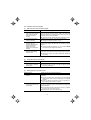
6.3 If an Alarm Code Appears on the LED Monitor
[1]
0cn Overcurrent protection
Problem
The inverter output current momentarily exceeded the overcurrent level.
Overcurrent occurred during acceleration.
Overcurrent occurred during deceleration.
Overcurrent occurred when running at a constant speed.
0c1
0c2
0c3
Possible Causes
What to Check and Suggested Measures
(1) The inverter output
terminals were
short-circuited.
Remove the wires connected to the inverter output terminals
(U, V, and W) and measure the interphase resistance. Check if
the resistance is too low.
Î Remove the part that short-circuited (including replacement
of the wires, relay terminals and motor).
(2) Ground faults occurred at
the inverter output
terminals.
Remove the wires connected to the inverter output terminals
(U, V, and W) and perform a Megger test.
(3) Loads were too heavy.
Measure the motor current with a measuring device, and to
trace the current trend. Therefore, use this information to judge
if the trend is over the calculated load value for your system
design.
Î Remove the part that short-circuited (including replacement
of the wires, relay terminals and motor).
ÎIf the load is too heavy, decrease it or raise the inverter
capacity.
Trace the current trend and check if there are any sudden
changes in the current.
Î If there are any sudden changes, make the load variation
smaller or raise the inverter capacity.
Î Enable instantaneous overcurrent limiting (H12 = 1).
(4) The value set for torque
boost (F09) was too large.
(F37 = 0, 1, 3, or 4)
Check that the output current decreases and the motor does
not come to stall if you set a lower value than the current one
for F09.
Î Lower the value for torque boost (F09) if the motor is not
going to stall.
(5) The acceleration/
deceleration time was too
short.
Check that the motor generates enough torque required during
acceleration/deceleration. That torque is calculated from the
moment of inertia for the load and the acceleration/
deceleration time.
Î Increase the acceleration/deceleration time (F07, F08, E10,
E11, and H54).
Î Enable current limiting (F43).
Î Raise the inverter capacity.
(6) Malfunction caused by
noise
Check if noise control measures are appropriate (e.g., correct
grounding and routing of control and main circuit wires).
Î Implement noise control measures. For details, refer to
"Appendix A" of the FRENIC-Mini User’s Manual (MEH446).
Î Enable the retry function (H04).
6-9
[2]
0un Overvoltage protection
Problem
The DC link bus voltage was over the detection level of overvoltage.
Overvoltage occurs during the acceleration.
Overvoltage occurs during the deceleration.
0u3 Overvoltage occurs during running at constant speed.
0u1
0u2
Possible Causes
What to Check and Suggested Measures
(1) The power supply voltage
was over the range of the
inverter’s specifications.
Measure the input voltage.
(2) The acceleration time was
too short.
Check if the overvoltage alarm occurs after sudden
acceleration.
Decrease the voltage to within that of the specifications.
Increase the acceleration time (F07, E10, and H54).
Select the S-curve pattern (H07).
Consider the use of a braking resistor.
(3) The deceleration time was
too short for the moment
of inertia for load.
Recalculate the deceleration torque from the moment of inertia
for load and the deceleration time.
(4) Loads were suddenly
removed.
- Check if the alarm occurs when loads are suddenly
removed.
- Check if the inverter operation suddenly changes from
driving operation to braking operation.
(5) Braking load was too
heavy.
Compare the braking torque of the load with that of the inverter.
(6) Malfunction caused by
noise.
Check if the DC link bus voltage was below the protective level
when the alarm occurred.
Increase the deceleration time (F08, E11, and H54).
Enable automatic deceleration (H69=1) so that when the
DC link bus voltage exceeds the overvoltage suppression
level, the inverter changes the deceleration time to three
times longer than the set value.
Set the rated voltage (at base frequency) (F05) to 0 to
improve braking ability.
Consider the use of a braking resistor.
Consider the use of a braking resistor.
Set the rated voltage (at base frequency) (F05) to 0 to
improve braking ability.
Consider the use of a braking resistor.
Improve noise control. For details, refer to "Appendix A" of
the FRENIC-Mini User’s Manual (MEH446).
Enable the retry function (H04).
[3]
lu Undervoltage protection
Problem
DC link bus voltage was below the undervoltage detection level.
Possible Causes
(1) A momentary power
failure occurred.
What to Check and Suggested Measures
Reset the alarm.
If you want to restart running the motor by not treating this
condition as an alarm, set F14 to "4" or "5," depending on
the load.
6-10
Possible Causes
What to Check and Suggested Measures
(2) The power to the inverter
was switched back on too
soon (with F14 = 1)
Check with LED monitor if the power to the inverter was
switched back on although its control circuit was still operating.
(3) The power supply voltage
did not reach the range of
the inverter’s
specifications.
Measure the input voltage.
(4) Peripheral equipment for
the power circuit
malfunctioned, or the
connection was incorrect.
Measure the input voltage to find where the peripheral
equipment malfunctioned or which connection is incorrect.
(5) Other loads were
connected to the same
power system and
required a large current to
start running to the extent
that it caused a temporary
voltage drop on the supply
side.
Measure the input voltage and check the voltage variation.
(6) Inverter's inrush current
caused the power voltage
drop because power
transformer capacity was
insufficient.
Check if the alarm occurs when you switch on a molded case
circuit breaker, an earth leakage circuit breaker (with
overcurrent protection) or a magnetic contactor.
[4]
Make the interval longer for re-power on.
Increase the voltage to within that of the specifications.
Replace any faulty peripheral equipment, or correct any
incorrect connections.
Reconsider the power system configuration.
Reconsider the capacity of the power transformer.
lin Input phase loss protection
Problem
Input phase loss occurred, or interphase voltage unbalance rate was large.
Possible Causes
What to Check and Suggested Measures
(1) Main circuit power input
wires broken.
Measure the input voltage.
(2) The terminal screws for
the main circuit power
input of the inverter were
not tight enough.
Check if the screws on the inverter input terminals have
become loose.
(3) Interphase unbalance rate
of three-phase voltage
was too large.
Measure the input voltage.
(4) Overload cyclically
occurred.
Measure ripple wave of DC link bus voltage.
(5) Single-phase voltage was
inputted to the inverter
instead of three-phase
voltage input.
Check the inverter type.
Repair or replace the wires.
Tighten the terminal screws to the recommended torque.
Connect an AC reactor (ACR) or a DC reactor (DCR) to
lower the rate.
Raise the inverter capacity.
If the ripple is large, raise the inverter capacity
Obtain a new inverter that meets the power supply
specifications.
6-11
[5]
0pl Output phase loss protection
Problem
Output phase loss occurred.
Possible Causes
What to Check and Suggested Measures
(1) Inverter output wires are
broken
Measure the output current.
(2) Wire for motor winding are
broken
Measure the output current.
(3) The terminal screws for
inverter output were not
tight enough.
Check if any screw on the inverter output terminals has
become loose.
(4) A single-phase motor has
been connected
[6]
Replace the output wires.
Replace the motor.
Tighten the terminal screws to the recommended torque.
Single-phase motors cannot be used. Note that the
FRENIC-Mini only drives three-phase induction motors.
0h1 Overheat protection for heat sink
Problem
Temperature around heat sink rose.
Possible Causes
What to Check and Suggested Measures
(1) Temperature around the
inverter exceeded that of
inverter specifications.
Measure the temperature around the inverter.
(2) Accumulated running time
of the cooling fan
exceeded the standard
period for replacement, or
the cooling fan
malfunctioned.
Check the cumulative running time of the cooling fan. Refer to
Chapter 3, Section 3.2.2 [5], "Reading Maintenance
Information."
Visually check that the cooling fan rotates normally.
(3) Air vent is blocked.
Check if there is sufficient clearance around the inverter.
Lower the temperature around the inverter (e.g., ventilate
the panel well).
Lighten the load.
Replace the cooling fan.
Replace the cooling fan.
Increase the clearance.
Check if the heat sink is not clogged.
Clean the heat sink.
(4) Load was too heavy.
Measure the output current.
Lighten the load (e.g. lighten the load before the overload
protection occurs using the overload early warning (E34).
Decease the motor sound (carrier frequency) (F26).
Enable the overload protection control (H70).
6-12
[7]
0h2 External alarm input
Problem
External alarm was inputted (THR).
Possible Causes
What to Check and Suggested Measures
(1) An alarm function of the
external equipment was
activated.
Inspect external equipment operation.
(2) Connection has been
performed incorrectly.
Check if the wire for the external alarm signal is correctly
connected to the terminal to which the "Alarm from external
equipment" has been assigned.
(3) Incorrect settings.
Check if the "Alarm from external equipment" has not been
assigned to an unassigned terminal.
Remove the cause of the alarm that occurred.
Connect the wire for the alarm signal correctly.
Correct the assignment.
[8]
0h4 PTC thermistor for motor protection
Problem
Temperature of the motor rose abnormally.
Possible Causes
What to Check and Suggested Measures
(1) Temperature around the
motor exceeded that of
motor specifications.
Measure the temperature around the motor.
(2) Cooling system for the
motor malfunctioned.
Check if the cooling system of the motor is operating normally.
(3) Load was too heavy.
Measure the output current.
Decrease the temperature.
Lighten the load.
Repair or replace the cooling system of the motor.
Lighten the load (e.g., lighten the load before overload
occurs using the overload early warning (E34) function).
Decrease the temperature around the motor.
Increase the motor sound (carrier frequency) (F26).
(4) The set activation level
(H27) of the PTC
thermistor for motor
overheat protection was
inadequate.
Check the thermistor specifications and recalculate the
detection voltage.
(5) A PTC thermistor and
pull-up resistor were
connected incorrectly or
the resistance was
inadequate.
Check the connection and the resistance of the pull-up resistor.
(6) The value set for the
torque boost (F09) was
too high.
Check the data of function code F09 and readjust the data so
that the motor does not stall even if you set the data to a lower
value.
(7) The V/f pattern did not
match the motor.
Check if the base frequency (F04) and rated voltage at base
frequency (F05) match the values on the nameplate on the
motor.
Reconsider the data of function code H27.
Correct the connections and replace the resistor with one
with an appropriate resistance.
Readjust the data of the function code F09.
Match the function code data to the values on the nameplate
of the motor.
6-13
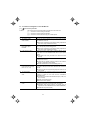
[9]
dbh Overheat protection for braking resistor
Problem
Thermal protection for braking resistor activated.
Possible Causes
What to Check and Suggested Measures
(1) Braking load was too
heavy.
Recalculate the relation between the braking load and braking
capacity.
Lighten the braking load.
Reconsider the choice of the braking resistor in order to
improve braking ability. Resetting the data of function codes
F50 and F51 is also required.
(2) The deceleration time was
too short.
Recalculate the required deceleration torque and time from the
moment of inertia for the load and the deceleration time.
Increase the deceleration time (F08, E11, and H54).
Reconsider the choice of the braking resistor in order to
improve the braking ability. Resetting the data of function
codes F50 and F51 is also required.
(3) Incorrect values have
been set for the data of
function codes F50 and
F51.
Check the braking resistor specifications.
Reconsider and change the data of function codes F50 and
F51.
Note: The inverter does not detect the overheating alarm of a braking resistor by monitoring its
surface temperature, but by monitoring its load magnitude.
Therefore, even if the surface temperature itself does not rise, the alarm may be detected if the
resistor is used more frequently than the set data of function codes F50 and F51. If you use the
resistor to the limit of its capacity, you must adjust the data of function codes F50 and F51 while
checking the surface temperature of the resistor.
[ 10 ] 0l1 Electronic thermal overload relay
Problem
Electronic thermal function for motor overload detection was activated.
Possible Causes
What to Check and Suggested Measures
(1) Load was too heavy.
Measure the output current.
Lighten the load (e.g., lighten the load before overload
occurs using the overload early warning (E34)).
(2) The acceleration/
deceleration time was too
short.
Check that the motor generates enough torque for
acceleration/deceleration. This torque is calculated from the
moment of inertia for the load and the acceleration/
deceleration time.
Increase the acceleration/ deceleration time (F07, F08, E10,
E11 and H54).
(3) The characteristics of
electronic thermal did not
match those of the motor
overload.
Check the motor characteristics.
(4) Activation level for the
electronic thermal relay
was inadequate.
Check the continuous allowable current of the motor.
Reconsider the data of function codes P99, F10 and F12.
Use an external thermal relay.
Reconsider and change the data of function code F11.
6-14
[ 11 ] 0lu Overload protection
Problem
Temperature inside inverter rose abnormally.
Possible Causes
What to Check and Suggested Measures
(1) Temperature around the
inverter exceeded that of
inverter specifications.
Measure the temperature around the inverter.
(2) The service life of the
cooling fan has expired or
the cooling fan
malfunctioned.
Check the cumulative running time of cooling fan. Refer to
Chapter 3, Section 3.2.2 [5], "Reading Maintenance
Information."
Lower the temperature (e.g., ventilate the panel well).
Lighten the load.
Replace the cooling fan.
Visually check that the cooling fan rotates normally.
Replace the cooling fan.
(3) Air vent is blocked.
Check if there is sufficient clearance around the inverter.
Increase the clearance.
Check if the heat sink is not clogged.
Clean the heat sink.
(4) Load was too heavy.
Measure the output current.
Lighten the load (e.g., lighten the load before overload
occurs using the overload early warning (E34)).
Decrease the motor sound (carrier frequency) (F26).
Enable overload prevention control (H70).
(5) The acceleration/
deceleration time was too
short.
Recalculate the required acceleration/deceleration torque and
time from the moment of inertia for the load and the
deceleration time.
Increase the acceleration/deceleration time (F07, F08, E10,
E11 and H54).
(6) The wires to the motor are
too long and caused a
large amount of current to
leak from them.
Measure the leak current.
Insert an output circuit filter (OFL).
[ 12 ] er1 Memory error
Problem
Error occurred in writing the data to the memory in the inverter.
Possible Causes
(1) While the inverter was
writing data (especially
initializing data), power
supply was turned off and
the voltage for the control
circuit dropped.
What to Check and Suggested Measures
key resets the alarm after the
Check if pressing the
function code data are initialized by setting the data of H03 to
1.
Return the initialized function code data to their previous
settings, then restart the operation.
6-15
Possible Causes
What to Check and Suggested Measures
(2) A high intensity noise was
given to the inverter while
data (especially initializing
data) was being written.
Check if appropriate noise control measures have been
implemented (e.g., correct grounding and routing of control
and main circuit wires). Also, perform the same check as
described in (1) above.
Improve noise control. Alternatively, return the initialized
function code data to their previous settings, then restart the
operation.
(3) The control circuit failed.
Initialize the function code data by setting H03 to 1, then reset
the alarm by pressing the
key and check that the alarm
goes on.
This problem was caused by a problem of the printed circuit
board (PCB) (on which the CPU is mounted). Contact your
Fuji Electric representative.
[ 13 ] er2 Remote keypad communications error
Problem
A communications error occurred between the remote keypad and the inverter.
Possible Causes
What to Check and Suggested Measures
(1) Break in the
communications cable or
poor contact.
Check continuity of the cable, contacts and connections.
(2) A high intensity noise was
given to the inverter.
Check if appropriate noise control measures have been
implemented (e.g., correct grounding and routing of control
and main circuit wires).
Replace the cable.
Improve noise control. For details, refer to "Appendix A" of
the FRENIC-Mini User’s Manual (MEH446).
(3) The remote keypad
malfunctioned.
Check that alarm er2 does not occur if you connect another
remote keypad to the inverter.
(4) The RS-485
communications card
malfunctioned.
Check that alarm er2 occurs even if you connect another
remote keypad to the inverter.
Replace the remote keypad.
Replace the card.
[ 14 ] er3 CPU error
Problem
A CPU error (e.g. erratic CPU operation) occurred.
Possible Causes
What to Check and Suggested Measures
(1) A high intensity noise was
given to the inverter.
Check if appropriate noise control measures have been
implemented (e.g. correct grounding and routing of control and
main circuit wires).
Improve noise control.
6-16
[ 15 ] er6 Operation protection
Problem
An error occurred due to incorrect operation of the motor.
Possible Causes
What to Check and Suggested Measures
(1) The
key was pressed
when H96 = 1 or 3.
Even though a run command was present at the input terminal
or the communication port, the inverter was forced to
decelerate to stop and er6 was displayed.
(2) The start check function
was activated when H96 =
2 or 3.
When one of the following conditions occurred while a run
command was present at the input, the inverter did not run and
er6 was displayed:
If this was not intended, check the setting of H96.
- The power was switched on
- An alarm was released
- The inverter was switched to link command LE operation.
Review the running sequence to avoid input of the run
command when er6 has occurred.
If this was not intended, check the setting of H96.
(To reset the alarm, turn the run command off.)
[ 16 ] er8 RS-485 communications error
Problem
A communications error occurred during RS-485 communications.
Possible Causes
What to Check and Suggested Measures
(1) Host controllers (e.g.,
PLCs and personal
computers) did not
operate due to incorrect
settings and/or defective
software/hardware.
Check the controllers.
(2) RS-485 converter did not
operate due to incorrect
connections and settings,
or hardware defective.
Check the RS-485 converter (e.g., check for poor contact).
(3) Broken communications
cable or poor contact.
Check continuity of the cable, contacts and connections.
(4) Even though no response
error detection time (y08)
has been set,
communications did not
occur cyclically.
Check the host controllers.
(5) A high intensity noise was
given to the inverter.
Check if appropriate noise control measures have been
implemented (e.g., correct grounding and routing of control
and main circuit wires).
Remove the cause of the controller error.
Change the various RS-485 converter settings, reconnect
the wires, or replace the converter with a recommended
device as appropriate.
Replace the cable.
Change the settings of host controller software, or make the
no response error detection time invalid (y08=0).
Improve noise control.
Improve noise reduction measures on the host side.
Replace the relay converter with a recommended insulated
converter.
6-17
Possible Causes
What to Check and Suggested Measures
(6) Conditions for
communications differ
between the inverter and
host controllers.
Compare the settings of the y codes (y01 to y10) with those of
the host controllers.
(7) The RS-485
communications card
malfunctioned.
Correct any settings that differ.
Replace the card.
[ 17 ] erf Data save error during undervoltage
Problem
The inverter was unable to save data such as the frequency commands, timer
operation time, and PID process command set through the keypad when the power
was switched off.
Possible Causes
What to Check and Suggested Measures
(1)
The control circuit voltage
dropped suddenly while
data was being saved
when the power was
turned off, because the
DC link bus was rapidly
discharged.
Check how long it takes for the DC link bus voltage to drop to
the preset voltage when power is turned off.
(2) A high intensity noise
affected the operation of
the inverter while data was
being saved when the
power was turned off.
Check if appropriate noise control measures have been
implemented (e.g., correct grounding and routing of control
and main circuit wires).
(3) The control circuit failed.
Check if erf occurs each time power is switched off.
Remove whatever is causing the rapid discharge of the DC
key and releasing the
link circuit. After pressing the
alarm, set, using a remote keypad, the data of the relevant
function codes (such as the frequency commands, timer
operation time, and PID process command) back to the
original values and then restart the operation.
key and
Improve noise control. After pressing the
releasing the alarm, set, using a remote keypad, the data of
the relevant function codes (such as the frequency
commands, timer operation time, and PID process
command) back to the original values and then restart the
operation.
This problem was caused by a problem of the printed circuit
board (PCB) (on which the CPU is mounted). Contact your
Fuji Electric representative.
6-18
6.4 If an Abnormal Pattern Appears on the LED Monitor while No Alarm Code is
Displayed
[1]
– – – – (center bar) appears
Problem
A center bar (– – – –) has appeared on the LED monitor.
Possible Causes
What to Check and Suggested Measures
(1) When PID control had
been disabled (J01=0),
you changed E43 (item
selection) to 10 or 12.
Make sure that when you wish to view other monitor items, E43
is not set to "10" or "12."
Set E43 to a value other than "10" or "12."
You disabled PID control
(J01=0) when the LED
monitor had been set to
display the PID final
command value or PID
feedback amount by
key.
pressing the
Make sure that when you wish to view a PID process command
or a PID control command, PID control is still in effect or J01 is
not set to 0.
(2) While timer operation is
disabled (C21=0), E43
(item selection) has been
set for 10 or 12.
Make sure that when you wish to view other monitor items, E43
is not set to "13."
While timer operation is
enabled (C21=1), it has
been disabled (C21=0)
during setting the LED
monitor to display the
timer value by pressing
key.
the
(3) Connection to the remote
keypad was broken.
Set J01 to 1 or 2.
Set E43 to a value other than "13."
Make sure that when you wish to view the timer (s), timer
operation is still in effect or C21 is not set to 0.
Set C21 to 1.
key does not take
Prior to proceed, check that pressing the
effect for the LED display.
Check connectivity of the cable for the remote keypad.
Replace the cable.
Check whether the connector on the RS-485 Communications
Card or on the remote keypad is not broken.
Replace the RS-485 Communications Card or the remote
keypad with a new one.
6-19
[2]
_ _ _ _ (under bar) appears
Problem
key
An under bar ( _ _ _ _ ) appeared on the LED monitor when you pressed the
or entered a normal start/stop command FWD or a reverse start/stop command
REV. The motor did not start.
Possible Causes
What to Check and Suggested Measures
(1) The voltage of the DC link
bus was low (F14 = 4, 5).
Select 5_01 under Menu #5 "Reading maintenance
information" in Programming mode on the keypad, and check
the voltage of the DC link bus, which should be: 200 VDC or
below for three-phase 200 V, single-phase 200 V, and single
-phase 100 V; and 400 VDC or below for three-phase 400 V.
Plug the inverter to a power supply that meets its input
specifications.
[3]
Problem
appears
Parentheses (
) has appeared on the LED monitor while the keypad displaying
the Drive Monitor.
Possible Causes
What to Check and Suggested Measures
(1) The data to be displayed
could not fit the LED
monitor.
Check that the product of the output frequency and the display
coefficient (E50) does not exceed 9999.
Adjust the setting of E50.
6-20