1
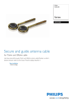
LED HDTV/DVD COMBO
USER’S MANUAL
MODEL
SKYWORTH ELECTRONICS,INC
Phone: 626 336-3698
FAX: 626 336-3238
Email: [email protected]
1312 john Reed Court
City of Industry, CA 91745
USER’S MANUAL
SLC-1519A-3S
SLC-1919A-3S
SLC-2219A-3S
For Sales Information Please Contact
RoadTrucker Inc (www.RoadTrucker.com
8312 Sidbury Rd. Wilmington, NC 28411
(800) 507-0482 / (910) 686-4281
Safety Information
Warning
To prevent fire and/or electric shock, do not use this plug with an extension
cord, receptacle or other outlet unless the blades can be fully inserted to
prevent blade exposure. Do not expose this appliance to rain or moisture.
AVIS
RISQUE DE CHOC ELEC TRIOUE/NE PAS OUVRIR
Important Safety Instructions
Read these instructions.
Keep these instructions.
Heed all warnings.
Follow all instructions.
Please, unplug the TV power cord when the following conditions occur:
-When there is a thunderstorm (Please, pull out the power cord and antenna).
-When cleaning the TV set.
-When the TV set is not used for a long time.
Do not use corrosive depurative when cleaning the TV set.
Do not put the TV set under direct sunlight or near heat.
Do not put a heat source, such as a candle or heater, on top of or near the TV set.
Leave plenty of space (al least 10cm) around the TV set for ventilation.
Place the TV set away from where it can be ruined by rain or water (such as near a
window).
Don't put a container with liquid (such as a vase) on top of the TV set.
Do not move the TV set when the power is on.
Do not touch, push or scratch the surface of the TV set with hard materials or items.
When TV surfaces are dirty, please use a wet cotton cloth or soft cloth with noncorrosive cleaners
to clean it carefully. Don´t use acetone, toluene or alcohol to clean the TV set.
Be aware and careful of moisture, which can damage inner electronic components.
When condensed
moisture is present, the TV screen may appear blurry or spotty.
It is recommended that a technician install the TV set on a wall, if such placement is
desired.
An incorrect wall installation will be unsafe and hazardous.
Do not let children climb on or play around the TV set to avoid falls, collissions,
damages and injuries.
Do not hit the TV panel with hard objects to prevent damages.
Do not cover the TV set with blankets or other objects when it is connected to a
power source to prevent overheating and fire.
Batteries shall not be exposed to excessive heat such as sunshine, fire or the like.
Mains plug is used as disconnect device from the mains, the disconnect
device shall remain readily operate.
Apparatus with class I construction shall be connected to a mains socket
outlet with a protective earthing connection.
Important Safety Precautions
Please, immediately pull out the AC power
plug
from adapter if there is an abnormal sound or
smell or the LED TV has sound but no picture,
and contact after sales support.
The LED TV should be kept free from rain,
moisture and dust to prevent electrical
shock and
short circuits. Do not cover the ventilation
openings with table clothes, curtains,
newspapers, etc.
The LED TV should be kept from high
temperature heating sources or direct
sunlight. Good ventilation is required.
Allow 10 cm. between the LED TV and
other appliances or built-in cabinet walls.
When you wipe the front cabinet, please
make sure the power plug is pulled out and
use a soft, dry, lint-free cloth and handle it
with care. Do not repeatedly wipe the panel,
nor scrape, tap or strike the panel with a hard
object.
Do not wipe the LED TV with any petrol,
chemical or alcohol based solvents as it
will lead to product damage of the panel
and cabinet.
Important Safety Precautions
Do not place the LED TV on an unstable
surface.
Do not place the power cord or other cables
across a walkway in case it is trampled on. Do
not overload the power cord or power socket.
When the power plug is used to disconnect and
connect the device, it should easily into the
power source.
Do not disassemble the back cover, as it
contains high voltages inside and will cause
electric shock. Only qualified professionals
should conduct internal adjustments,
maintenance, and checks.
The TV set should not be subjected to
water droplets, vapor, or splash. This
equipment should not be placed on objects
filled with liquids. Do not place flame
sources, such as lit candles, on or near the
LED TV. Please, pull out the power plug
and contact after sales support if there are
abnormal objects or water in the TV.
Pull out the power cord and antenna cable
during electrical storms so the LED TV is not
damaged by electrical surges. Keep all
people away from the antenna cable during
electrical storms.
ENERGY STAR Qualification.
This product has earned the ENERGY STAR for meeting U.S. Federal energy efficiency guidelines as set
by the Department of Energy and Environmental protection agency.
The ENERGY STAR program exists to provide energy saving guidelines and help promote energy efficient
products and practices. Changes to certain features, settings and functions of this TV can change and/or
increase its power consumption.
As-shipped mode is the mode in which the product qualifies for ENERGY STAR .
Table of Contents
Introduction
Features
Accessories
Specifications
Table of Contents
3
3
4
20
BASIC OPERATION
20
Picture
21
Audio
21
5
Time
Overview of front and side panel
5
Setup
Overview of back panel
6
7-9
Lock
22
22
23-24
General Description
10
Antenna connection
10
External Connection
Connecting VCR
Connecting DVD Player/Set-Top Box via HDMI
Connecting Digital Audio System
Connecting Amplifier/DVD Home Theater
Connecting DVD Player/Set-Top Box via HDMI
Connecting PC
Connecting S-VIDEO
Connecting a Headphone
11
11
12
13
14
15
16
17
18
Supporting signals
18
Basic operation
19
Turning the TV On and Off
1
Menu system introduction
DVD Setup Menu
25
DVD OPERATION
26
Troubleshooting
27
Picture defects and the reason
28
19
2
Introduction
Introduction
Features
WSpecifications
arnings
Input terminals used for external equipment connection
Model
One Computer VGA/PC input
One PC Audio input
One
One
One
One
One HDMI input
One USB(only update) input
One YPbPr input
One L/R Audio output
One S-VIDEO input
AV input
EARPHONE output
ANTENNA input
COAXIAL output
Power Consumption
SLC-1519A-3S
SLC-1919A-3S
SLC-2219A-3S
1366X768
1366X768
1920X1080
24W
32W
42W
3
3
2
2
1
2
1
2
1
15 4 Dx6 4 Wx12 4 H 18 4 Dx6 4 Wx13 8 H 21 8 Dx7 8 Wx15 8 H
6.6 lbs
Sound output(Max)
7.7 lbs
9.4 lbs
2 x 5W
E
Fine digital control
IN PUT
AC 100-240V, 50/60Hz
Adapter requirement
OUT PUT
Quick setup Guide
Display screen type
DC: 12V
3A/5A/5A
Color active matrix LED display
NTSC System, ATSC System
Remote Control &
Batteries (AAAx 2)
Instructions
Manual
Quick Setup Guide
Antenna: 2~69; Cable: 1~135 (Analog: 1-125,
Digital: 1-135)
NTSC3.58
75W
(Unbalance)
o
o
0 C-40 C
Note:
1. In case of any design change, a notice will not be released.
Power Cord
3
Car charger cable
Adapter
4
USB
13
EARPHONE
OUT
Overview of back panel
12
IN
Overview of front and side panel
RF
General Description
11
L
COAXIAL
OUT
R
General Description
SPEAKER
REMOTE CONTROL SENSOR
If an optional remote control is allowed,
aim it towards this spot on the TV.
POWER INDICATOR
Green: In power on mode.
Red: In standby mode.
SOURCE
Toggles between all the available input
sources ( TV, AV, S-VIDEO, COMPONENT,
DVD, HDMI, VGA)
MENU
Press to see an on-screen menu of your
TV's features.
5
4
8
CH+/Press to change channels.
In the on-screen menu, use the CH +/buttons as up/down arrow buttons.
VOL+/Press to increase or decrease the volume.
In the on-screen menu, use the VOL +/buttons as left/right arrow buttons.
POWER
Press POWER button to toggle between
normal and standby mode.
DC 12V
HDMI 1
VGA
IN
IN
IN
PC
AUDIO
IN
1
2
3
4
1. POWER( DC 12V ) input
2. HDMI
Connect to the HDMI jack of a device
with an HDMI output.
3. VGA/PC IN
Connect to the video output jack on
your PC.
4. PC AUDIO
Audio input for external devices
5. COMPONENT
Connect Component video.
6. COMPOSITE VIDEO
Video input for external devices, such
as a camcorder or VCR.
7. S-VIDEO COMPOSITE
COMPONENT AUDIO
Audio inputs for external devices.
5
Y
Pb
Pr
VIDEO
IN
5
L
9
IN
6
S-VIDEO
7
10
8
R
IN
6
7
8. S-VIDEO
Connect an S-VIDEO signal from a
camcorder or VCR...
9. COAXIAL
Connect to a Digital Audio devices.
10. AUDIO OUT
Connect to the audio output jacks
on your amplifier/home theater.
11.RF
Connect to an antenna or cable
NTSC & ATSC.
12.EARPHONE
Connect a set of phone for private
listening
13.USB
USB input
6
News,
Music, Movie, Sports and Custom.
Vivid, Soft, Custom.
16:9,
Letter Box, Panorama, 4:3.
Press to turn ON/Off closed captions.
7
8
x
x
Antenna connection
Antenna input impedance of this unit is 75ohm. VHF/UHF 75ohm coaxial cable can be
connected to the antenna jack directly, if the antenna cable is 300ohm parallel flat feeder
cable, you need to use the 300ohm/75ohm converter to connect the antenna cable to the
antenna jack. For details Please refer to the following drawing.
Antennas with 75 ohm Round Leads
Antennas with 300 ohm flat twins Leads
Use a 75ohm - 300ohm converter
ANT IN
75ohm coaxial cable
300ohm coaxial cable
Antenna cable
Antenna feeder
9
10
External Connection
External Connection
Connecting VCR
Connecting DVD Player/Set-Top Box
These instructions assume that you have already connected your TV to an antenna or a
cable TV system. Skip step 1 if you have not yet connected to an antenna or a cable
system.
The rear panel jacks on your TV make it easy to connect a DVD to your TV.
DVD Player/Set-Top Box
OUT
USB
EARPHONE
IN
R
RF
OUT
IN
Audio Cable (Not supplied)
R
RF
EARPHONE
USB
VCR Rear Panel
DC 12V
HDMI 1
VGA
IN
IN
IN
PC
AUDIO
IN
Y
Pb
IN
Pr
VIDEO
L
R
IN
Follow the instructions in Viewing a VCR or Camcorder Tape to view your VCR tape.
Each VCR has a different back panel configuration.
When connecting a VCR, match the color of the connection terminal to the cable.
We recommend the use of cables with a Ferrite Core.
1. Unplug the cable or antenna from the back of the TV.
2. Connect the cable or antenna to the ANT IN terminal on the back of the VCR.
3. Connect an RF Cable between the ANT OUT terminal on the VCR and the ANT IN
terminal on the TV.
4. Connect a Video Cable between the VIDEO OUT jack on the VCR and the VIDEO IN
jack on the TV.
5. Connect Audio Cables between the AUDIO OUT jacks on the VCR and the AUDIO L and
AUDIO R jacks on the TV.
If you have a mono (non-stereo) VCR, use a Y-connector (not supplied) to hook up to
the right and left audio input jacks of the TV. If your VCR is stereo, you must connect
two cables.
11
L
DC 12V
HDMI 1
VGA
IN
IN
IN
PC
AUDIO
IN
Y
Pb
IN
OUT
COAXIAL
S-VIDEO
Component Cable (Not supplied)
IN
S-VIDEO
RF Cable (Not supplied)
Pr
VIDEO
L
IN
L
COAXIAL
Video Cable (Not supplied)
OUT
Audio Cable (Not supplied)
R
IN
Component video separates the video into Y (Luminance (brightness)), Pb (Blue) and Pr
(Red) for enhanced video quality.
Be sure to match the component video and audio connections.
For example, if connecting the video cable to COMPONENT IN, connect the audio
cable to COMPONENT IN also.
Each DVD player/STB has a different back panel configuration.
When connecting a DVD player/STB, match the color of the connection terminal to the
cable.
We recommend the use of cables with a Ferrite Core.
1. Connect a Component Cable between the COMPONENT IN [Y, PB, PR] jacks on
the TV and the COMPONENT [Y, PB, PR] jacks on the DVD player.
2. Connect Audio Cables between the COMPONENT IN [R-AUDIO-L] jacks on the TV
and the AUDIO OUT jacks on the DVD player.
12
External Connection
External Connection
Connecting Digital Audio System
Connecting Amplifier/DVD Home Theater
The rear panel jacks on your TV make it easy to connect a Digital Audio System to your TV.
DC 12V
HDMI 1
VGA
IN
IN
IN
PC
AUDIO
IN
Y
Pb
IN
Pr
VIDEO
L
OUT
IN
USB
EARPHONE
RF
OUT
1. Connect an COAXIAL Cable between the SPDIF jacks on the TV and the Digital Audio
Input jacks on the Digital Audio System. When a Digital Audio System is connected to the
SPDIF terminal: Decrease the gain (volume) of the TV, and adjust the volume level with
the system's volume control.
HDMI 1
VGA
IN
IN
IN
PC
AUDIO
IN
Y
Pb
IN
Pr
VIDEO
L
IN
COAXIAL
L
DC 12V
OUT
R
EARPHONE
IN
R
IN
5.1 CH audio is possible when the TV is connected to an external device supporting 5.1
CH.
We recommend the use of cables with a Ferrite Core.
13
S-VIDEO
COAXIAL Cable (Not supplied)
Audio Cable (Not supplied)
IN
S-VIDEO
COAXIAL
L
OUT
R
Digital Audio System
RF
USB
Digital Audio System
R
IN
Each external input source device has a different back panel configuration.
When connecting an external device, match the color of the connection terminal to the
cable.
We recommend the use of cables with a Ferrite Core.
1. Connect Audio Cables between the AUDIO L and R OUT on the TV and AUDIO IN [RAUDIO-L]on the Amplifier/DVD Home Theater.
When an audio amplifier is connected to the AV OUT [R-AUDIO-L] terminals: Decrease
the gain (volume) of the TV, and adjust the volume level with the Amplifier's volume control.
14
External Connection
External Connection
Connecting DVD Player/Set-Top Box via HDMI
Connecting PC
This connection can only be made if there is a HDMI Output connector on the external
device.
PC
VGA
IN
IN
PC
AUDIO
IN
Y
Pb
IN
Pr
VIDEO
L
EARPHONE
OUT
RF
IN
R
L
COAXIAL
OUT
OUT
IN
S-VIDEO
COAXIAL
L
HDMI 1
IN
OUT
R
D-Sub Cable (Not supplied)
IN
S-VIDEO
HDMI Cable (Not supplied)
DC 12V
PC AUDIO Cable (Not supplied)
IN
EARPHONE
RF
USB
USB
DVD Player/Set-Top Box
DC 12V
HDMI 1
VGA
IN
IN
IN
PC
AUDIO
IN
Y
Pb
IN
Pr
VIDEO
L
R
IN
R
IN
Each PC has a different back panel configuration.
The HDMI jacks do not support PC connection.
We recommend the use of cables with a Ferrite Core.
What is HDMI.
HDMI, or high-definition multimedia interface, is a next-generation interface that enables
the transmission of digital audio and video signals using a single cable without
compression.
Multimedia interface is a more accurate name for it especially because it allows multiple
channels of digital audio (5.1 channels).
The difference between HDMI and DVI is that the HDMI device is smaller in size, has the
HDCP(High Bandwidth Digital Copy Protection) coding feature installed, and supports
multi-channel digital audio.
Each DVD player/STB has a different back panel configuration.
We recommend the use of cables with a Ferrite Core.
1. Connect a D-Sub Cable between RGB/PC IN connector on the TV and the PC output
connector on your computer.
2. Connect the PC audio input jackc on the TV
1. Connect an HDMI Cable between the HDMI connector on the TV and the
HDMI connector on the DVD player/Set-Top Box.
15
16
External Connection
External Connection
Connecting S-VIDEO
Connecting a Headphone
S-VIDEO
L
R
HDMI 1
VGA
IN
IN
IN
PC
AUDIO
IN
Y
Pb
IN
Pr
VIDEO
L
OUT
USB
EARPHONE
IN
COAXIAL
OUT
L
R
IN
Connect the S-VIDEO output of the DVD or VCR to the S-VIDEO input on the set.
The picture quality is improved, compared to connecting a regular VCR to the
video input.
Connect the Audio output of the DVD or VCR to the Audio input jacks on the set
using the RCA cable.
Select S-VIDEO input source with using the SOURCE button on the remote
control.
S-VIDEO
DC 12V
HDMI 1
VGA
IN
IN
IN
PC
AUDIO
IN
Y
Pb
IN
Pr
VIDEO
L
IN
L
DC 12V
Headphone Cable
IN
S-VIDEO
COAXIAL
OUT
R
RF
OUT
USB
EARPHONE
IN
DateTraver
R
DVD
RF
USB
AV
R
IN
Supporting signals
1360X768
1920X1080
Note : only 22 ” can support the resolution of 1920x1080
17
18
Basic Operation
OSD Menu Operations
Turning the TV On and Off
Adjust the OSD Screen
1. How to turn the TV on or off
1. After attaching cable to either an antenna or a cable service, insert the power cord plug
into a polarized AC outlet.
button on the LED TV.
2. Press
3. Normal picture will be displayed on the screen after
6 seconds. If no signal input, "No Signal" will be
displayed on the screen.
4. If temporary POWER off is required, press button on the LED TV.
5. If you want to completely switch off the power for this unit, unplug the power cord plug
for this unit.
6. After switching off the unit, you should turn on the TV again at least 5 seconds later.
Status indication lamp
Green: In power on mode.
Red: In standby mode.
Auto power off
If there is no signal input in any Mode, the TV will automatically accesses the standby
state in about 15 minutes.
Memory before turning TV off
The settings of picture and the preset channels will be memorized at turning off the unit.
When being started up again, the unit will work according to the mode set before being
turned off.
Press SOURCE button to display the input source list;
Press ▼ / ▲ button to select the input source you want to watch;
Press ▶ button to enter the input source;
INPUT SOURCE
TV
AV
S-VIDEO
Component
DVD
HDMI
PC
ENTER
BASIC OPERATION
CHANNEL
Press MENU button to display the main menu.
Press◄ / ► button to select CHANNEL in the main menu, it will highlight the first option.
Air/Cable
Air
Auto Scan
Favorite
Show/Hide
L
Channel
Channel No.
Channel Label
DTV Signal
Bad
Air/Cable
press ENTER buttons to select it Cable or Air.
AUTO SCAN
Auto Tuning can find out all effective channel automatically.
Press ▼/▲ to select Auto Tuning, then press ENTER to start
auto searching.
If you want to stop searching, press EXIT.
Auto Scan
Scan all channels
Digital channel only
Analog channel only
MENU
19
ENTER
20
OSD Menu Operations
Adjust the OSD Screen
OSD Menu Operations
TIME
Press MENU button to display the main menu.
Press◄ / ► button to select TIME in the main menu, it will highlight the first option.
PICTURE
Press MENU button to display the main menu.
Press◄ / ► button to select PICTURE in the main menu, it will highlight the first option.
Sleep Timer
Atlantic
DST
Off
Time Format
L
Picture
Picture Mode
Standard
Color Mode
Normal
Zoom Mode
Normal
3DNR
Weak
DLC
On
PICTURE MENU
Press MENU to display the main menu, and press ◄ /► to select the Picture Menu.
Highlight the item and press ▼/▲ to select corresponding sub-menu.
Picture Mode: Dynamic/Standard/Soft/ Personal.
Color mode:This item can adjust the saturation of the color based on your own like.
Zoom mode: Four selectable Zoom Modes, Normal, Zoom, Cinema, Wide .
3DNR: Used for the noise reduction adjustment to get a better image effects.
DLC: Dynamic brightness control
AUDIO
24-hour
Auto Sync
On
Clock
WakeUp
2012/1/1 12:0
2012/1/1 12:0
TIME MENU
Press MENU to display the main menu, and press ◄ /► to select the Time Menu.
Sleep Timer: Select the time in minutes(5min,10min,15min,30min,60min,90min,120min,
180min,240min,Personal) that you want the TV to shut off automatically after you set the
time. Cancel by setting it to Off.
Time Zone: Set to choose the time belt.
DST: Press ENTER to select the DST on or off.
Time Format: Set to choose time display format
Auto Sync: Synchronous automatic
Clock:Press ENTER to set time.
Wake Up: Ending the state of sleep
SETUP
Press MENU button to display the main menu.
Press◄ / ► button to select AUDIO in the main menu, it will highlight the first option.
Equalizer
AudioL
Time L
Off
Time Zone
Press MENU button to display the main menu.
Press◄ / ► button to select SETUP in the main menu, it will highlight the first option.
Personal
MTS
STEREO
Digital Output
Surround
PCM
Off
Audio Only
AVC
Off
Off
Menu Language English
Transparency
25%
Closed Caption
Restore Default
SetupL
AUDIO MENU
Press MENU to display the main menu, and press ◄ /► to select the Sound Menu.
Equalizer : Adjust audio frequency band.
MTS: Set the MTS (ATV mode).
Digital Output: Press ▼ button to highlight Digital Output. then press the enter buton to
select it .
Surround : Surround effect on or off.
Audio Only: Audio Only effect on or off.
AVC: When set the AVC on, quick volume change will be smoothed.
21
Setup Wizard
Blue Screen
Off
SETUP MENU
Press MENU to display the main menu , and press◄/► to select the Set u p Menu.
Menu Language: Set the OSD display language. (English/ French/ Spanish)
Transparency: Set transparency of OSD.
Closed Caption: Set to hide the caption
Restore Default: Recall the default setting.
Setup Wizard: Installation guide.
Blue Screen: Set the background color to blue or black when no input signal.
22
OSD Menu Operations
OSD Menu Operations
Adjust the OSD Screen
LOCK
Press MENU button to display the main menu.
Press◄ / ► button to select LOCK in the main menu, it will highlight the first option.
Parental Controls___
INPUT BLOCK
Press ENTER to display the Input Block , Press ▼ / ▲ button to select (TV、AV、
Component、HDMI、 PC、USB )
press◄/► button to select “UnBlock” or “Block”.
US
Press ENTER button for to enter to US ratings menu, which contains two sub-menus:
MPAA Rating and TV Rating.
Lock L
TV RATING
TV-Y
ALL
US
TV-Y7
ALL
TV
MPAA
TV-G
ALL
TV-PG
ALL
V
S
L
D
TV-14
ALL
V
S
L
D
TV-MA
ALL
V
S
L
FV
Block
Press MENU button to display the main menu.
Press ◄ / ► button to select Lock in the main menu. It will highlight the first option.
Enter the code 0000 to enter the parental menu (see the picture below),
or press MENU to cancel.
MPAA
G
PG
PG-13
R
NC-17
MENU
Change Password
System Lock
On
Unrated Lock
Off
Lock
N/A
MENU
CANADA
Press ENTER button for to enter to CANADA ratings menu, which contains two sub-menus:
Canada English and Canada French.
Input Block
Lock L
X
ENTER
US
Canada
RRT Setting
Reset RRT
Canada
Canada Eng
Enter Old Password
CHANGE PASSWORD
Press ENTER button and enter a new 4 digit password.
SYSTEM LOCK
Press ENTER to select the system lock on or off.
UNRATED LOCK
Press ENTER to select the Unrated lock on or off.
Canada Fre
Enter New Password
Confirm Password
MENU
Clear
Cancel
ENTER
Canada Eng
C
Canada Fre
G
C8+
8 ans+
G
13 ans+
PG
16 ans+
14+
18+
18 ans+
Lock
Lock
EXEMPT
EXEMPT
MENU
23
MENU
24
DVD OPERATION
- - Preference Page - TV Type
TV Display
Wide
Eng
Subtitle
Eng
Disc Menu
Eng
Parental
OSD Lang
Eng
Password
Captions
Off
Default
Last Memory
Off
Source
Disc
USB
- - General Setup Page - -
NTSC
Audio
Go To Preference Page
DVD Support List:
5.SOURCE: Select to Disc, USB or Card.
- - General Setup Page - Downmix
Press
button on the side panel or on the remote controller.
After placed a disc in the disc tray,
press
button to play the disc,and
press
button twice to pause.
5.
STR
Go To Speaker Setup Page
Default Password is 8888.
6.
7.
25
26
Troubleshooting
Picture defects and the reason
Disconnect the power cord, wait 60 seconds then
reconnect the power cord and restart the TV.
C
Increase the volume.
please check sound settings.
C
No support for this function.
E
E
E
E
For Sales Information Please Contact
RoadTrucker Inc (www.RoadTrucker.com
8312 Sidbury Rd. Wilmington, NC 28411
(800) 507-0482 / (910) 686-4281
27
28