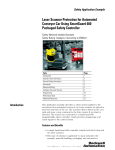
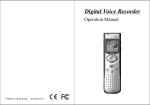
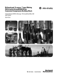
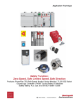
1
Safety Application Example
Laser Scanner Protection for Automated
Conveyor Car Using MSR200 Series Modular
Safety Relay
Non-networked (Hard-wired) Example
Safety Rating: Category 3 according to EN954-1
Introduction
Topic
Page
Introduction
1
Important User Information
2
General Safety Information
3
Description
3
Setup and Wiring
5
Configure the Laser Scanner
6
Performance Data
11
Additional Resources
12
This application example describes a safety system applied to the
movement of an automated conveyor car. Laser scanners are placed in
the front and back of the car. The scanners detect objects in the car’s
path and issues a stop command to the drive motors if an object is
detected. The scanners are connected to an MSR200 safety relay,
which monitors both scanners and the E-Stop push button.
Features and Benefits
• A single MSR200 relay controls both the E-Stop and two laser
scanners.
• No safety control programming is required.
• This type of solution is applicable to many industries (for
example, material handling, packaging, and automotive).
2
Laser Scanner Protection for Automated Conveyor Car Using MSR200 Series Modular Safety Relay
Important User Information
Solid state equipment has operational characteristics differing from those of
electromechanical equipment. Safety Guidelines for the Application,
Installation and Maintenance of Solid State Controls (publication SGI-1.1
available from your local Rockwell Automation sales office or online at
http://literature.rockwellautomation.com) describes some important
differences between solid state equipment and hard-wired electromechanical
devices. Because of this difference, and also because of the wide variety of
uses for solid state equipment, all persons responsible for applying this
equipment must satisfy themselves that each intended application of this
equipment is acceptable.
In no event will Rockwell Automation, Inc. be responsible or liable for
indirect or consequential damages resulting from the use or application of
this equipment.
The examples and diagrams in this manual are included solely for illustrative
purposes. Because of the many variables and requirements associated with
any particular installation, Rockwell Automation, Inc. cannot assume
responsibility or liability for actual use based on the examples and diagrams.
No patent liability is assumed by Rockwell Automation, Inc. with respect to
use of information, circuits, equipment, or software described in this manual.
Reproduction of the contents of this manual, in whole or in part, without
written permission of Rockwell Automation, Inc., is prohibited.
Throughout this manual, when necessary, we use notes to make you aware
of safety considerations.
WARNING
IMPORTANT
ATTENTION
Publication SAFETY-AT003A-EN-P - October 2007
Identifies information about practices or circumstances that can cause
an explosion in a hazardous environment, which may lead to personal
injury or death, property damage, or economic loss.
Identifies information that is critical for successful application and
understanding of the product.
Identifies information about practices or circumstances that can lead
to personal injury or death, property damage, or economic loss.
Attentions help you identify a hazard, avoid a hazard, and recognize
the consequence.
SHOCK HAZARD
Labels may be on or inside the equipment, for example, a drive or
motor, to alert people that dangerous voltage may be present.
BURN HAZARD
Labels may be on or inside the equipment, for example, a drive or
motor, to alert people that surfaces may reach dangerous
temperatures.
Laser Scanner Protection for Automated Conveyor Car Using MSR200 Series Modular Safety Relay
3
General Safety Information
This application example is for advanced users and assumes that you
are trained and experienced in safety system requirements.
IMPORTANT
A risk assessment should be performed to make sure all task and
hazard combinations have been identified and addressed. The risk
assessment may require additional circuitry to reduce the risk to a
tolerable level. Safety circuits must take into consideration safety
distance calculations which are not part of the scope of this
document.
ATTENTION
Contact Rockwell Automation to find out more about our safety risk
assessment services.
Description
Fixed
Fixed
Fixed
Fixed
Fixed
Conveyor
Conveyor
Conveyor
Conveyor
Conveyor
Line 1
Line 2
Line 3
Line 4
Line n
Wall
Warning
Zone
Safety
Zone Slow
Speed
Safety Zone
Fast Speed
Warning
Zone
Conveyor Car
Conveyor
Car
Scanner
Movement
Scanner
Fixed
Fixed
Fixed
Fixed
Fixed
Conveyor
Conveyor
Conveyor
Conveyor
Conveyor
Line 1
Line 2
Line 3
Line 4
Line n
The automated conveyor car moves forward and back within a
designated aisle. The conveyor transports materials from one fixed
conveyor line to another.
The conveyor car moves at two speeds: fast and slow. The safety zone
of the scanner must be adjusted for a longer range when moving fast
and can be adjusted for a shorter range when moving at slow speed.
Publication SAFETY-AT003A-EN-P - October 2007
4
Laser Scanner Protection for Automated Conveyor Car Using MSR200 Series Modular Safety Relay
Safety Function
When an object is detected in the safety zone, the conveyor car must
stop moving or must remain stopped if not moving. When the safety
zones are clear, the car can move.
Stopping Time and Safety Distance
Calculate the necessary safety field length using the formula:
Safety Field Length = SA + ZG + ZR + ZF + ZB.
where:
• SA = Stopping distance
• ZG = General safety supplement = 100 mm (3.94 in.)
• ZR = Supplement for any measurement error of the SafeZone
Multizone safety laser scanner related to reflection
• ZF = Supplement for any lack of ground clearance of the vehicle
• ZB = Supplement for the reduction in the braking performance
of the vehicle as defined in the related vehicle documentation
Refer to the SafeZone Multizone Safety Laser Scanner User Manual,
publication 75046-171-01(A), for details on the safety distance length
for mobile applications.
Example Bill of Materials
This safety application example uses these components.
Cat. No.
Description
Qty
SafeZone multizone laser sensor
2
442L-CSFZNMZ-20
Pre-wired Cable with memory module 20 m (65.6 ft) cable
2
440R-H23177
MSR211 modular safety relay
1
440R-H23196
MSR238 output module with delayed outputs
1
440L-SFZNMZ
(1)
800FM-MT44
E-Stop push button, twist-to-release, trigger action
1
800F-X01S
Self-monitoring contact block
1
800F-X01V
1 N.C. contact, low current QuadCONNECT
1
800F-15YE112
Yellow legend, 60 mm (2.36 in.), emergency stop
1
800FM-R611
Reset button, blue, flush operator, “R” legend, metal body
1
800F-MX10V
Metal latch, 1 N.O. contact, low voltage QuadCONNECT
1
800FM-P6
Reset-required pilot light, blue, round metal operator
1
800F-MN3B
Metal latch, LED, screw clamp, 24V dc, blue
1
(1) 442L-CSFZNMZ-10 is a 10 m (32.8 ft) cable.
Publication SAFETY-AT003A-EN-P - October 2007
Laser Scanner Protection for Automated Conveyor Car Using MSR200 Series Modular Safety Relay
Setup and Wiring
5
For detailed information on installing and wiring, refer to the product
manuals listed in the Additional Resources section on page 12.
System Overview
SafeZone Multizone
Laser Scanner
SafeZone Multizone
Laser Scanner
Contact Block
E-Stop Push Button
Reset-required
Pilot Light
S32 S42 S52 S62
S11 S21 S12 S22
13 14
34 44
24 A1
51 52
13 14
34 44
24 A1
51 52
MSR238P
MSR211P
Stop
Stop
Start
Dfwg
Pleig
S72 S82 X32 X42
Y31 Y32 Y33 Y30
Y1 Y2 S34 Y37
68 78 Y35 A2
Contact Block
Y1 Y2 S34 Y37
68 78 Y35 A2
Reset Button
Wiring
+24 VDC
SafeZone Multizone
Front
1
10
11
9
4
3
2
Field
Set
Selection
A1
A2
Warning Field
OSSD2
OSSD1
Field
SafeZone Multizone
Set
Rear
Selection
1
A1
10
A2
11
Warning Field
9
OSSD2
4
OSSD1
3
2
E-Stop
Delay set by
jumpers
(4s shown)
Y31 Y40 Y41 Y42 13 23
A1 S12 S32
31
Y3 Y4 Y5 Y6 17 27 35
MSR238
440R-H23196
Delayed
MSR211P
440R-H23177
A2 S42 S62 Y30 Y32 Y33 S34 Y1 Y2 14 24
32
Y3 Y4 Y7 Y8 18 28 36
Master Relay
Push to Reset
Object in
Warning Field
Feedback
Contacts
from
Stopping
Devices
B
Immediate
Stop
Signal
Delayed
Stop
Signal
24V DC Com
Publication SAFETY-AT003A-EN-P - October 2007
6
Laser Scanner Protection for Automated Conveyor Car Using MSR200 Series Modular Safety Relay
Each scanner can have two separate, selectable field sets, with each
set consisting of a warning field and a safety field. The field sets are
selected by inputs A1 and A2. The A1 and A2 inputs use a
combination of one normally closed and one normally open contact
to help reduce the probability of a fault due to shorting.
Both scanners are active all the time. To prevent nuisance stops, the
field of the scanner not in use should be set to the slow field.
An object in the warning field of either scanner will energize a signal.
This allows personnel to back away from the car before a safety stop
is initiated.
The MSR211 relay continuously monitors both scanners and the
E-Stop push button. The safety zone of each scanner must be clear
and the E-Stop must be reset for the MSR211 relay to be ready for
reset. Pressing the reset activates (closes) the safety outputs of the
MSR211 and MSR238 relays.
Obstructing either scanner's safety zone or pressing the E-Stop will
initiate a stop. The safety outputs of the MSR211 relay will open to
remove power to the motor drivers. The safety outputs of the MSR238
relay will open after the configured time delay expires. The time delay
is set by jumpers.
Refer to the Rockwell Automation Safety Products Catalog or MSR211
instruction sheet, listed in the Additional Resources section on
page 12, for other timing options (0.5… 300 s).
Configure the Laser
Scanner
The software dialogs on the following pages illustrate the steps and
configuration settings needed to configure this application example
using the Configuration Assistant in the Safety Configuration and
Diagnostic (SCD) software.
TIP
The SafeZone Multizone software cannot run while RSLinx software
is running. In your icon tray, right-click the RSLinx icon and choose
Shutdown RSLinx. RSLinx software automatically loads again when
you run RSNetworx for DeviceNet software.
The default password for the laser scanner is ABGM. For
demonstration purposes, log in as an Authorized Client.
Publication SAFETY-AT003A-EN-P - October 2007
Laser Scanner Protection for Automated Conveyor Car Using MSR200 Series Modular Safety Relay
7
1. Enter a name for your application.
2. Enter a unique name for the SafeZone MultiZone scanner.
3. Choose the type of application to indicate whether the SafeZone
MultiZone scanner is operated on a stationary machine or
mobile vehicle.
4. Configure the scanner.
Publication SAFETY-AT003A-EN-P - October 2007
8
Laser Scanner Protection for Automated Conveyor Car Using MSR200 Series Modular Safety Relay
5. Choose the OSSD configuration for the scanner.
6. Configure the scanner’s inputs.
7. Configure the scanner’s output.
Publication SAFETY-AT003A-EN-P - October 2007
Laser Scanner Protection for Automated Conveyor Car Using MSR200 Series Modular Safety Relay
9
8. Choose the type of restart for the scanner.
The Configuration Assistant dialog provides information about
each type of restart.
9. Create two field sets for the scanner.
10. Review and finalize the configuration for each field set you
created.
Publication SAFETY-AT003A-EN-P - October 2007
10
Laser Scanner Protection for Automated Conveyor Car Using MSR200 Series Modular Safety Relay
11. Enter the user name you want to appear in the configuration
protocol and diagnostic reports.
12. Repeat these configuration steps for the second scanner.
TIP
Publication SAFETY-AT003A-EN-P - October 2007
Press the PgDn key to let the program download. The “Acknowledge”
becomes live.
Laser Scanner Protection for Automated Conveyor Car Using MSR200 Series Modular Safety Relay
Performance Data
11
These field sets for the laser scanner are provided as examples. The
actual field sets depend on the conveyor aisle and the conveyor
speed. For demonstration purposes, the fields are asymmetric and
short.
Publication SAFETY-AT003A-EN-P - October 2007
Additional Resources
For more information about the products used in this example, refer
to these resources.
Resource
Description
SafeZone Multizone Safety Laser Scanner
User Manual, publication 75046-171-01(A).
Provides information on installing, wiring,
configuration, commissioning, and
troubleshooting a SafeZone scanner.
Safety Relay - Minotaur MSR211P
Installation Instructions, publication
57518/1.
Provides information on operation,
installation, wiring, and technical
specifications for the MSR211P safety relay.
Rockwell Automation Safety Products
Catalog, publication S115.
Provides information on Rockwell
Automations safety product offerings.
Industrial Automation Wiring and Grounding Provides general guidelines for installing a
Guidelines, publication 1770-4.1
Rockwell Automation industrial system.
Product Certifications website,
http://ab.com
Provides declarations of conformity,
certificates, and other certification details.
You can view or download publications at
http://literature.rockwellautomation.com. To order paper copies of
technical documentation, contact your local Rockwell Automation
distributor or sales representative.
Allen-Bradley, Rockwell Automation, SafeZone, Minotaur, RSNetWorx for DeviceNet, RSLinx, and
QuadCONNECT are trademarks of Rockwell Automation, Inc.
Trademarks not belonging to Rockwell Automation are property of their respective companies.
Publication SAFETY-AT003A-EN-P - October 2007 12
Copyright © 2007 Rockwell Automation, Inc. All rights reserved. Printed in the U.S.A.