1
E84 Data Logging Device (DLD) User Manual
Revision 2.8
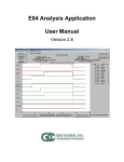
The graph shows a solid black vertical line at the far left of the display. This is a DLD Power On Indicator.
Following a series of signal changes, the graph displays a second vertical line whose color ranges from
red (near the top of the display) to green (in the middle), back to red and ends in black. This colored
vertical line is the DLD Power Down Indicator.
A second DLD Power On Indicator is shown towards the right of the graph window, followed by a second
IR Transceiver Test. No signal lines are graphed between the DLD Power Down and Power Up
indicators. A final DLD Power Down Indicator is shown at the far right of the graph window.
Status LED’s
Two status LED’s were added to the DLD for hardware revision 2. No other changes were made during
this hardware revision. Revision 1 DLD’s do not include the two status LED’s, but are otherwise identical
to revision 2 DLD’s.
The two status LED’s are positioned to the left of the DB-9 connector.
DLD Power Indicator
The DLD Power Indicator is a green LED that indicates that power is applied to the DLD. This LED is ON
anytime the DLD is powered up. If the DLD is properly connected to an E84 compliant connector, and the
Power Indicator LED is OFF, the unit should be returned to GCI for service.
DLD RAM Buffer Indicator
The DLD RAM Buffer Indicator is a red LED that flashes based on the status of the DLD’s internal RAM
buffer. The rate at which the LED flashes is related to how full the internal RAM buffer is. The following
table shows the relationship between the RAM buffer status and LED flash rate.
RAM Buffer Status
Flash Rate
Less than 1/4 full
OFF
Between 1/4 and 1/2 full
2 Hz (2 flashes per second)
Between 1/2 and 3/4 full
4 Hz (4 flashes per second)
More than 3/4 full
8 Hz (8 flashes per second)
Full / overwriting existing data
Solid ON
E84_DLD_User_Manual.wpd
8