1
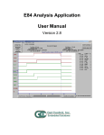
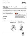
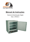
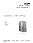
MICROENVIRONMENTS
SB300 FOSB (FRONT OPENING
SHIPPING BOX) FOR 300 MM WAFERS
User manual
SB 300 FOSB for 300 mm wafers
Table of Contents
Introduction . . ......................................... 2
Specifications . . ....................................... 9
Features . . ..............................................
Terminology .............................................
FIMS Compatibility . . ..................................
Automated Ergonomic Handling .. .................
Identification ............................................
Cleanability ..............................................
Equipment Interface ...............................
Load Port Interface. . ..................................
Features .................................................
Standard Operation .. .................................
Door Interface Points ................................
Bottom Interface Points .. ...........................
2
2
2
2
2
2
10
10
10
10
11
11
Components and Materials ........................ 3
Door ........................................................ 3
Shell . . ...................................................... 4
General Use Instructions ......................... 13
Manual Assembly. . ..................................... 13
D-ring Handles . . ....................................... 13
Secondary Packaging ............................... 4
Standard Two-pack . . .................................. 4
For More Information ............................. 14
Assembly Instructions .............................. 5
SB300 Options .. ......................................... 5
Product Warranties ................................ 14
Datum Orientation ..................................
Horizontal Datum.......................................
Facial Datum ............................................
Bilateral Datum ........................................
X, Y and Z Dimensions . . ..............................
Structure .................................................
Terms and Conditions .. ............................ 14
6
6
6
6
6
6
SEMI® Standards .. ..................................... 8
Entegris, Inc.
1
SB 300 FOSB for 300 mm wafers
Introduction
The SB300 is an innovative 300 mm shipper
designed to offer the benefits associated with
manual and FIMS-compatible automation
handling in a FOSB. The dual-functionality
of the door allows users to easily move from
manual operation to FIMS.
Features
Terminology
Ergonomic Manual Handling
• FIMS (Front Opening Interface Mechanical
Standard) is the specification characterizing
the automated interface between a FOSB and
related equipment, as defined by SEMI® E62
• FOSB (Front Opening Shipping Box) is a wafer
shipping box with a front-opening interface, as
defined by SEMI M31
• Door design allows safe and easy opening
and closing in manual mode
• Ergonomically designed side handles
allow safe carrying of the box
FIMS Compatibility
• Provides FIMS automation benefits
in a FOSB
• Reduces labor costs associated with
manual door operation
• Allows maximum 300 mm loadport
interoperability
• Ensures accurate equipment interaction
Secure Wafer Protection
• Automated operation minimizes potential
contamination from human interaction
• Wafer plane accuracy
• Ultrapure, low outgassing materials provide
superior protection for wafer shipment
• Protects wafers during 1.5 m drop tests
• All plastic assembly prevents metallic
contamination and corrosion
Identification
• Innovative insert-molded barcode ensures
lifetime identification and traceability
• Clear polycarbonate door and shell allow
visual observation of wafers
• Info pads to detect FOSB differences
• Built-in horizontal RFID holder in KC plate
• Vertical RFID holder optional
• Colored door panels optional
Cleanability
• Designed for liquid flow-through and drying
• Complete door assembly can be cleaned
without disassembly
2Entegris, Inc.
SB 300 FOSB for 300 mm wafers
Components and Materials
Door
Number
Component
Material
1
Wafer strip
Thermoplastic elastomer (TPE)
1
2
Wafer cushion
Polycarbonate (PC)
1
3
Gasket
Thermoplastic elastomer (TPE)
1
4
Corner guides
Catalogue (POM)
4
5
Door housing
Polycarbonate (PC)
1
6
Lift arms
PTFE-filled polycarbonate (white)
4
7
Latch arms
Acetal (POM)
4
8
Latch cams
PTFE-filled polycarbonate (white)
2
9
Latch cover
Polycarbonate (PC)
2
1
2
3
4
Quantity
5
Entegris, Inc.
6
7
8
9
3
SB 300 FOSB for 300 mm wafers
Shell
Number
Component
Material
Quantity
1
Shell housing
Polycarbonate (PC)
1
2
Rear retainer
Polybutylene
terephthalate (PBT)
1
3
KC plate
Polycarbonate (PC)
1
4
Filter housing
Polycarbonate (PC)
1
5
O-ring
Viton®
1
6
Filter media
Electrostatic media
1
7
Auto flange
(optional)
Black polycarbonate
(PC)
1
8
Side handles
(optional)
Black polycarbonate
(PC)
2
9
Info pads
(optional)
Black polycarbonate
(PC)
4
1
7
8
6
5
2
9
4
3
Secondary Packaging
Standard Two-pack
The standard package for SB300 delivery from our
factory to the customer with unattached accessories
is shown in Figure 1. All parts are single bagged.
Outer Box
Entegris part # FLA-054-01
Dimensions: 680 mm L × 415 mm W × 365 mm H
(26.77" L × 16.34" W × 14.37" H)
Corrugated pad
Entegris part # FLA-052-03
Dimensions: 393.7 mm L × 337.82 mm
(15.5" L × 13.3" W)
This package was designed to fit a standard pallet
size of 1100 mm × 1100 mm without overhang.
Pallet layers contain eight units, maximizing utilization of pallet space.
NOTE: This secondary packaging is not designed to
ship the SB300s with wafers.
4Entegris, Inc.
SB 300 FOSB FOR 300 MM WAFERS
Assembly Instructions
SB300 Options
Auto Flange
To install the auto flange:
Shell opening
1. Locate tab on auto flange, part number
SP300-1003.
2. Insert auto flange on the top of SB300 with
tab facing to the SB300 door opening.
3. Pull/push the auto flange until the snap is
through the opening on the SB300 shell.
Side Handles
To install 30-degree handles:
1. Locate the snap detail on the side handle,
part number SP300-0900.
2. Place the side handle so both the snap detail
and the leading tab of the handle are under the
support loops of the shell.
3.WhilesupportingthefrontoftheSB300,pushthe
handle further into the support loops on the shell
until the snap detail has locked into position.
To install 90-degree handles (shown in view to
the right):
1. Locate the snap detail on the side handle.
2. Place the side handle against the SB300 so
that the snap detail at the base of the handle
isunderthelower(KCplateside)supportloop
of the SB300.
3. Move the handle downward so that the snap
detail at the top of the handle is under the upper
support loop.
4. Move the handle upward until the snap detail
at both top and bottom of the handle are locked
into position.
Info Pad
To install the info pads:
1. Locate the “flat” side of the info pad,
part number 01-031822.
2. Align the flat portion of the info pad with the flat
portionontheKCplateinfopadhole.
3. Place the snap features into the desired info pad
hole and push the info pad into position until an
audible “snap” is heard. The info pad will sit flush
withthesurfaceoftheKCplateafterinstallation.
ENTEGRIS, INC.
5
SB 300 FOSB for 300 mm wafers
Datum Orientation
Horizontal Datum
The horizontal datum is located near the bottom
of the carrier (Figure 1). Frame location for the
purpose of automated transfer in and out of the
cassette is defined in the Z direction relative to
this datum.
Left to right
Front to back
–Y
–X
+X
+Y
Bilateral
datum
Facial
datum
Up +Z
Facial Datum
The facial datum is a vertical plane centered on
the film frame and oriented left to right. It is used
as a reference for front to back Y dimensions.
Horizontal datum
Figure 1. Datum orientation
Bilateral Datum
The bilateral datum is a vertical plane centered
on the wafers and oriented front to back. It is used
as a reference for left to right X dimensions.
X, Y and Z Dimensions
X dimensions are horizontal left to right.
Y dimensions are horizontal front to back.
Z dimensions are vertical.
Bilateral
datum
Horizontal datum
Structure
Datum Orientation Relative to the
First Wafer
All 300 mm wafers, when fully seated in the
shipper, are nominally centered on the vertical
line formed by the intersection of the bilateral
datum and the facial datum (Figure 2). The bottom of the first wafer, located in the lowest pocket
of the FOSB, is located nominally at 44 mm above
the horizontal datum.
Facial
datum
44 mm
Figure 2. Datum structure
Bilateral
datum
Facial
datum
Wafer Spacing
Each wafer above the first wafer is located
nominally at 10 mm spacing. The tolerance for
vertical wafer location is ±0.5 mm for each wafer
(Figure 3). The tolerance is non-accumulative.
Figure 3. Wafer spacing
and tolerance
+ 0.5 mm
- 0.5 mm
6Entegris, Inc.
SB 300 FOSB for 300 mm wafers
Kinematic Coupling Pins Relative to All Datum
120 mm
(4.72”)
Facial datum
2 × 80 mm
(3.15”)
Datum Orientation Relative to an SB300 FOSB
The base of the SB300 FOSB is located slightly
above the horizontal datum (Figure 5). The
bilateral datum and facial datum intersect
the FOSB vertically.
Bilateral datum
The horizontal datum is defined by the kinematic
coupling (Figure 4). The machine side of the kinematic coupling consists of three pins of a specified
shape in a specified pattern relative to the bilateral
datum and facial datum. The kinematic coupling
pins protrude through the horizontal datum. A
FOSB cannot be effectively opened, closed, loaded
or unloaded unless it is properly positioned on a
kinematic coupling.
Front of Pod
2 × 115 mm
(4.53”)
Figure 4. Top view of kinematic coupling
Bilateral
datum
Facial
datum
Horizontal datum
Figure 5. Datums and kinematic coupling
Entegris, Inc.
7
SB 300 FOSB for 300 mm wafers
SEMI Standards
SEMI E106
Provided below is a brief description of each
applicable SEMI standard and how it applies to
the SB300. Please contact your local Entegris
representative for information on specific SEMI
standard compliance issues.
Provisional Overview Guide for Physical
Interfaces and Carriers for 300 mm Wafers
SEMI E62
Provisional Specification for 300 mm Front
Opening Interface Mechanical Standard (FIMS)
SEMI E62 describes the features and basic function
of the FOSB door opening mechanism. E62 is a
very specific standard for the configuration of the
equipment, including registration pins, seal zones
and latch key shape, position, motion and torque.
The 300 mm FOSB must function with these
features but the precise mating feature size,
position and design are up to the carrier maker.
The features of the FOSB that mate with an E62
FOSB door opener are defined by the Entegris
design specification. In general, this compatibility
involves proper clearance around and location
relative to the E62 FOSB door opener features.
Since the force required to attach the door to
the shell is greater than the door closure force
designated by SEMI E62, the SB300 is designated
as “FIMS-compatible.”
SEMI M31-0999
Provisional Mechanical Specification for
Front Opening Shipping Box (FOSB) used
to Transport And Ship 300 mm Wafers
SEMI M31-0999 is a standard that partially specifies the FOSB used to ship 300 mm wafers from
wafer suppliers to their customers (typically IC
manufacturers). In this standard only the physical
interfaces for the FOSB are specified; no material
requirements or micro-contamination limits are
given. This standard assumes that the FOSB is
used in the last process in wafer manufacturing, in
acceptance and inspection, and in transferring the
wafers from a FOSB to a FOUP (Front Opening
Unified Pod) or open cassette inside an IC manufacturing process. The FOSB is not intended to be
used in IC manufacturing processes.
SEMI E106 describes the complex interdependencies among SEMI standards for 300 mm physical
interfaces and carriers, and explains how standards
apply to specific products.
SEMI E47.1
Provisional Mechanical Specification for
Boxes and Pods used to Transport and Store
300 mm Wafers
SEMI E47.1 is a standard that applies to various
types of 300 mm pods. The outside shape and overall pod size are limited by this standard. Equipment
automation and human interface features are also
defined by the standard.
SEMI E57
Provisional Mechanical Specification for
Kinematic Couplings used to Align and
Support 300 mm Wafer Carriers
SEMI E57 describes the equipment side of the kinematic coupling that is the universal equipment
interface for all types of 300 mm wafer carriers.
This standard describes very specifically the shape
and position of three pins. The 300 mm carrier
must have features, which register with these pins,
but the shape of these features is up to the carrier
maker to design. The test of a wafer carrier’s
compliance to E57 can only be made by placing
that carrier on a fixture that is compliant to SEMI
E57 and measuring the locations of features
relative to the resulting datum structure.
8Entegris, Inc.
SB 300 FOSB for 300 mm wafers
Specifications
• Wafer size: 300 mm (11.81") diameter
• Wafer capacity: 25
• Wafer spacing: 10 mm (0.40")
• Wafer carrier type: FOSB
• Overall dimensions
–Height from horizontal datum plane
(including auto-top flange):
336.93 mm (13.265")
–
Width: 385.17 mm (15.164")
–
Width (with handles): 415.369 mm
(16.369")
–
Depth: 332.77 mm (13.101")
415.8 mm (16.37”)
39.3 mm
(1.55”)
385.2 mm (15.16”)
363.7 mm (14.32”)
258.0 mm (10.16”)
25.5 mm
(1.00”)
332.8 mm (13.1”)
165.2 mm
(6.5”)
330.1 mm
(13.0”)
Facial
336.8 mm
(13.26”)
Entegris, Inc.
9
SB 300 FOSB for 300 mm wafers
Equipment Interface
The SB300 FOSB provides interoperability across
a variety of equipment. This section provides an
overview of one of the most common interfaces—
a load port—and then discusses the door interface
features and interfacing recommendations.
Door
registration
pins
Load Port Interface
Latch keys
Primary
hold down
A load port is a piece of equipment commonly
used to provide an interface between a FOSB
and a piece of process equipment. Basic load
port features are provided below.
Features
Port door
Kinematic
coupling
pins
Most load ports incorporate many of the same
basic features. These general features, defined in
SEMI standard E15.1, include:
• Door registration pins
• Kinematic coupling pins
• Port door
• Latch keys
• Primary hold down
Standard Operation
Basic load port operation is outlined below.
Operation of individual load port models will vary.
• The FOSB is placed on the load port and
located by the kinematic coupling pins
• The load port advances the FOSB to the port
door, engaging the primary hold down to retain
the FOSB on the load port
• The door registration pins locate the FOSB door
• The latch keys turn 90° to unlatch the
FOSB door
• The port door and FOSB door are removed, leaving the wafers accessible to the process tool
This basic procedure is reversed after the process
tool replaces the wafers in the FOSB.
10Entegris, Inc.
SB 300 FOSB for 300 mm wafers
Door Interface Points
Bottom Interface Points
Registration Hole and Slot
Kinematic Coupling
The registration hole and slot are used to properly
locate the door. Registration pins on load ports
interface with the round registration hole and
angled slot to ensure correct door location.
The kinematic coupling is used to precisely locate
the FOSB on equipment. It incorporates kinematic
coupling grooves that accommodate both standard
inner and outer kinematic coupling pins.
The hole and slot must both be used to properly
locate the door. See SEMI E62.
Recommendations
Automated Key Slots
Automated key slots are used for automated actuation of door latches and for retention of the door.
The key slots accommodate standard T-type keys.
The keys are inserted into the key slot and rotated
90° counterclockwise (as viewed from the FOSB)
to unlatch the door. In this position, the keys
securely hold the door for removal. When the door is
replaced in position, rotating the keys 90° clockwise
(as viewed from the FOSB side of the interface)
engages the door latches and allows the keys to
be removed.
The kinematic coupling is the only acceptable
interface mechanism for FOSBs and equipment
load ports. The primary outer pins offer increased
stability and accuracy, and are therefore recommenced for load port interface. The inner pins are
less accurate and are recommended for use only in
AMHS applications.
Related Specifications and Documents
• SEMI E57
Hold Down Features
The hold down features are used to retain the
FOSB in position. Two sets of features are provided. The primary hold down feature, located on
the front of the FOSB, is a passive restraint that
engages when the FOSB is advanced. The secondary hold down feature is an active restraint,
utilizing a keyway slot that accommodates a standard t-shaped key. The key is inserted into the
keyway slot and rotated 90° in either direction to
hold the FOSB in place.
To operate properly, the FOSB must be advanced
so it is within 0.5 mm of the load port bulkhead
(see SEMI E62). Torque required for key operation
is 4.4 Newton meters maximum.
Entegris, Inc.
11
SB 300 FOSB for 300 mm wafers
Recommendations
FEOL and BEOL Pads
The primary hold down is for use in applications
where the FOSB advances forward to engage the
feature. The secondary hold down can be used in
load port as well as AMHS applications. Use of the
hold down features is recommended to ensure the
FOSB cannot be removed from process equipment
prior to process cycle completion, and to prevent
the FOSB from falling or being knocked off of
transport equipment.
FEOL (front end of line) and BEOL (back end of
line) pads are used to prevent FEOL pods from
being processed on BEOL load ports and vice
versa, to prevent cross contamination of wafers.
Related Specifications and Documents
• SEMI E47.1
Sensor Pads
Sensor pads are used to verify FOSB presence and
proper placement.
Recommendations
Use of a pin on equipment to provide a physical
obstruction in the FEOL or BEOL positions is recommended rather than a presence sensor.
Related Specifications and Documents
• SEMI E1.9, E47.1, E15.1
Recommendations
For accurate operation, use only the recommended
sensor pads.
Related Specifications and Documents
• SEMI E1.9, E47.1
12Entegris, Inc.
SB 300 FOSB for 300 mm wafers
General Use Instructions
Manual Assembly
Proper manual assembly of the door to SB300
FOSB is accomplished by aligning the right or
left vertical edge of door to the shipper box
opening (see Figure 6).
Both the bottom Kinematic Coupling surface and
back surfaces of the shipper box should be supported when on the angled work surface. Selection
of most suitable angle to be used is dependent on
the height of the assembly workstation.
By using this method of assembly, errors are
greatly minimized. However, it is also required that
a visual inspection be performed after each assembly to make sure that the wafers are properly
engaged with the cushion in the door. This is most
easily done when viewing the wafers and cushion
through the center of the door.
Note: Assembly of the door should never be
attempted with the shipper box on its back with
the wafers in a completely vertical position as
this can result in cross slotting and wafer breakage (see Figure 8).
Figure 6.
Grip the door and shipper box along the vertical
edge (pivot edge) with one hand and rotate the
door until the wafer cushion contacts the wafers.
Latch the lock on the pivot edge first by rotating
the cam counter clockwise 90° using the tabs
available, manual latch keys or optional D-rings.
Apply inward pressure to the opposite side of the
door until it is flush to the shipper box opening
and latch closed using the same procedure.
It is possible to assemble the SB300 when seated
on a horizontal Kinematic Coupling plate, however to aid in assembly, Entegris recommends
that the shipper box be placed on an angled
surface of
15°–75° degrees as shown in Figure 7.
15°–75°
Figure 8.
D-ring Handles
Manual D-ring handles are used for manually
disengaging the door latches and for retention
of door. The D-ring handles also incorporate
automated key slots for automated operation.
The D-rings are simply lifted and then rotated 90°
clockwise to unlatch the door. In this position, the
D-rings provide a secure handle for removing and
replacing the door. When the door is replaced in
position, rotating the D-rings keys 90° counterclockwise engages the door latches.
Support to
prevent
tipping
Figure 7.
Entegris, Inc.
13
Recommendations
Make sure the door is properly seated before
engaging the latches.
Environmental Conditions
The SB 300 FOSB is packaged to meet industry
accepted cleanroom protocols. This packaging
can be used for storage until ready for use. Storage
temperature should not exceed 70°C (158°F).
Utilize your cleanroom protocol as a guide for
removing Entegris packaging material.
Product Reuse
If the FOSB is properly handled and maintained,
it is capable of being reused. In order to maximize
the number of reuses, the following guidelines
should be followed:
• Door and shell should be thoroughly cleaned
after each use
• The door gasket, wafer cushion and wafer strip
should be replaced after each use
• Thoroughly inspect the FOSB for damage
or excess wear prior to reuse
For More Information
Please call your Regional Customer Service
Center today to learn what Entegris can do
for you. Visit www.entegris.com and select the
Customer Service link for the center nearest you.
Terms and Conditions of Sale
All purchases are subject to Entegris’ Terms
and Conditions of Sale. To view and print
this information, visit www.entegris.com and
select the Legal Notices link from the footer.
Product Warranties
For Product Warranties, visit www.entegris.com
and select the Legal Notices link from the footer.
Entegris®, the Entegris Rings Design® and Creating a Material AdvantageS M are trademarks of Entegris, Inc.
Viton® is a trademark of DuPont Dow Elastomers, L.L.C.
SEMI® is a trademark of Semiconductor Equipment and Materials International Corporation
ENTEGRIS, INC.
Corporate Headquarters | 129 Concord Road | Billerica, MA 01821 USA
Customer Service Tel. +1 952 556 4181 | Customer Service Fax +1 952 556 8022
In North America 800 394 4083 | www.entegris.com
©2013 Entegris, Inc.
All rights reserved
Printed in USA
5550-7429ENT-0713