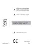
1
This operating instructions contains safety information
that if ignored can endanger life or result in serious
injury. They are indicated by this icon.
Use of this pump with radioactive chemicals is forbidden!
OPERATING INSTRUCTIONS
MANUAL FOR “V” PUMPS
Keep the pump protected from sun and water.
Avoid water splashes.
English language
Read Carefully!
R2-03-09
1
“V” series solenoid dosing pumps comply with the following European regulations:
EN60335-1 : 1995, EN55014, EN50081-1/2, EN50082-1/2, EN6055-2, EN60555,3
Based on directive CEE 73/23 c 93/68 (DBT Low voltage directive) and directive 89/336/
CEE (EMC Electromagnetic Compatibility)
GENERAL SAFETY GUIDELINES
Danger!
In emergencies the pump should be switched off immediately! Disconnect the power
cable from the power supply!
When using pump with aggressive chemicals observe the regulations concerning the
transport and storage of aggressive fluids!
When installing always observe national regulations!
Manufacturer is not liable for any unauthorized use or misuse of this product that may
cause injury, damage to persons or materials.
Caution!
Pump must be accessible at all times for both operating and servicing. Access must
not be obstructed in any way!
Feeder should be interlocked with a no-flow protection device.
Pump and accessories must be serviced and repaired by qualified and authorized
personnel only!
Always discharge the liquid end before servicing the pump!
Empty and rinse the liquid end before work on a pump which has been used with
hazardous or unknown chemicals!
Always read chemical safety datasheet!
Always wear protective clothing when handling hazardous or unknown chemicals!
2
1. Introduction
Introduction:
“V” Series metering pumps are the ideal solution for low / middle dosing
of chemicals. All control and setup parameters are available using accurate
control knobs and a visual system (led). “V” Series metering pumps
have digital On/Off switch to ensure dosing activities (available on some models
only).
Pump capacity:
Flow rate is determined by the stroke speed (frequency) adjustment. The stroke
speed is adjustable from 0 to 100% using the adjustment knob.
However dosing accuracy is guarantee within an adjustment range from 30% to
100%. The led on the panel shows the status activity of the pump.
3
2. Unpacking
Included into package:
n.4
n.4
n.1
n.1
n.1
n. 1
m2
m2
m2
n.1
Dibbles ø6
Self tapping screws 4,5 x 40
Delayed fuse 5 X 20
Foot filter with valve
Injection valve
Level probe (not included in VCO model)
Delivery pipe* (opaque PE)
Suction pipe * (transparent PVC)
Discharge pipe (transparent PVC 4x6)
This installation manual
*
If hose is 6x8 then there is only a 4mt long hose.
Cut to obtain suction and delivery hoses.
PLEASE DO NOT TRASH PACKAGING.
IT CAN BE USED TO RETURN THE PUMP.
4
3. General description
On/Off button
On/Off Led - Pump’s pulses
Stroke speed knob
Delivery valve
Discharge knob
Power supply
Suction valve
Level Probe Input
Note:
Shown image does not represent a specific pump’s model. It is only for general purpose.
5
4. Before to Install warnings
Pump’s installation and operativity is performed in 4 main steps:
Pump’s installation
Hydraulic Installation (hoses, level probe, injection valve)
Electrical Installation (main power connection, priming)
Programming the pump.
Before to start, please read carefully the following safety information.
IProtective clothes
Wear always protective clothes as masks, gloves, safety glasses and
further security devices during ALL installation procedure and while
handling chemicals.
Installation location
Pump must be installed in a safety place and fixed to the table / wall to
avoid vibration problems!
Pump must be installed in a easy accessible place!
Pump must be installed in horizontal position!
Avoid water splashes and direct sun!
Hoses and Valves
Suction and delivery hoses must be installed in vertical position!
All hoses connections must be performed using only hands’ force!
No tongs required!
Delivery hose must be firmly fixed to avoid suddenly movements
that could damage near objects!
Suction hose must be shorter as possible and installed in vertical
position to avoid air bubbles suction!
Use only hoses compatibles with product to dose! See chemical
compatibility table. If dosing product is not listed please
consult full Compatibility Table or contact chemical’s manufacturer!
6
5. Installation draw
Pump must be installed in a stable support at a maximum height (from tank’s bottom) of 1,5 meters.
4
3
1
8
2
5
6
1 - Dosing Pump
2 - Suction Hose
3 - Delivery Hose
4 - Injection Valve
5 - Air discharge
6 - Level Probe
7 - Foot Filter
8 - Power Cable
7
7
6. Hydraulic Installation
Hydraulic connections are:
Suction Hose with level probe and foot filter
Delivery Hose with injection valve
Discharge Hose
Suction Hose.
Completely unscrew tightening nut from pump’s head and remove assembling
components: tightening nut, holding ring and pipe holder.
Assembly as shown in fig. (A). Insert hose into pipe holder until it reaches the
bottom.
Lock hose on pump’s head by screwing down the tightening nut.
Use only hands to do it!
Connect other side of the hose to the foot filter using the same procedure.
Suction Hose
Tightening Nut
Holding Ring
Pipe Holder
O-ring
Valve
fig. (A)
8
6. Hydraulic Installation
Assembling foot filter with level probe.
Level probe must be assembled with foot filter using the provided kit.
Foot valve is made to be installed into tank’s bottom without sediments priming
problem.
STEP 5
STEP 4
INSERT RING AS SHOWN
STEP 3
INSERT PROBE
WITH N.O. CONTACT
UNTIL TO HEAR
A CLICK
STEP 2
INSERT FLOATER
STEP 1
INSERT RING AS SHOWN
Connect BNC from level probe into pump’s level input (front side of the pump).
Put level probe assembled with foot filter into tank’s bottom.
Warning: If there is a mixer installed into tank, install a suction lance
instead of level probe / foot filter.
Delivery Hose.
Completely unscrew tightening nut from pump’s head and remove assembling
components: tightening nut, holding ring and pipe holder.
Assembly as shown in fig. (A). Insert hose into pipe holder until it reaches the
bottom.
Lock hose on pump’s head by screwing down the tightening nut.
Use only hands to do it!
Connect other side of the hose to the injection valve using the same
procedure.
9
7. Pump head
Injection Valve.
Injection valve must be installed on plant from water’s input.
Injection valve will open at pressure greater than 0,3bar.
Discharge hose.
Insert one side of discharge hose into discharge connector as shown in fig (C).
Insert other side of discharge hose into product’s tank.
During priming procedure product exceeding will flow into tank.
To Delivery hose
Discharge Knob
Discharge hose
To Suction hose
fig (C)
For priming procedure see the related chapter.
10
7.1 Self venting pump head
Self-venting pump head.
to bleed hose
to delivery hose
to suction hose
Self-venting pump head must be used when using chemicals that produce
gas (i.e. hydrogen peroxide, ammonium, sodium hypoclorite at particular
conditions).
Hoses assembling procedure (including purge hose) is described in fig. (A).
Notes:
- suction, delivery and purge valves are DIFFERENT! Do not exchange them!
- delivery and purge hoses are made of same material!
- it’s allowed to lightly bend discharge hose!
- during calibration procedure (“TEST”) insert discharge hose into BECKER
test-tube!
11
8. Electrical installation
All electrical connections must be performed by AUTHORIZED AND QUALIFIED personnel only.
Before to proceed, please, verify the following steps:
- verify that pump’s label values are compatible with main power supply.
- pump must be connected to a plant with a differential switch (0,03A
sensitivity) if there isn’t a good ground.
- to avoid damages to the pump do not install it in parallel with heavy
inductance load (for example: engines). A relay switch must be used. See
below picture.
P - Dosing Pump
R - Relay
I - Switch or safety device
E - Electrovalve or inductance load
A - Main Power
- On pump’s mother board there is a further protection against over voltages
(275V - 150V) and distribution line noises (4KV for max 50μsec) as shown:
12
8. Electrical Installation
Once verified previous steps proceed as follows:
- check that “BNC” of level probe has been connected as described in “Hydraulic
Installation” chapter.
- connect “BNC” and external signal to pump’s “INPUT” connectors.
Level Probe Input 1
(bottom view)
1
Level Probe Input available on: VCL
13
9. Models
LEVEL ALARM
CL type pumps are provided with a liquid level alarm to indicate product tank is empty. The level probe
is connected to the right BNC plug on pump’s bottom panel. The level probe is made of a N.O. reed
contact (10VA, 1A max., 230Vac max.) closed by a floating magnet housed in a (PP) plastic box. When
the product level goes below the minimum the magnet closes the reed contact. The pump stops and
the red LED on pump’s front panel indicates the alarm status.
PUMP TYPES
Pumps mod. “VCLF” and “VCL” (12-24 Vac/Vdc) are equipped with a bicolour led.
Led on, red colour: low level product alarm. Check product’s tank and restore the level.
Led on, blinking green colour: pump normal operating mode.
Led on, blinking green colour (one second on, one second off): power supply out of range. Check pump’s
label and check the main power.
14
9. Models
VCO
Constant pump with flow control (front panel knob may be set from 0% to 100% of pump nominal
capacity). Flow control is electronically set and it operates on pump injections number. To avoid linearity
problem do not set the knob of pump flow between 0% and 10%.
VCO may operate in constant dosing mode or On-Off mode (using an external signal).
Dosing example using an VCO 0505: to dose 2,5 l/h at 5bar counter-pressure rotate front panel knob
to 50%.
VCO has a divider (x- 0,1) to reduce by ten times the pump capacity by dividing the pump stroke
speed.
How to enable “divider mode”:
- set the pump into OFF* mode;
- keeping pressed the on/off button, wait 3 flashes from the status led. The pump will start the dosing
activity with the stroke speed reduced ten times than the value set on stroke lenght knob.
To disable the “divider mode”, power OFF the pump. Keeping pressed the on/off button, wait 3 flashes
of the status led.
N/OF
F
on/off button
O
VCO
30
20
40 50 60
10
0
70
80
stroke lenght knob
90
100
%
status led
LED
The led on the frontal panel shows the pump’s operating status through 5 flashing:
LED ACTIVITY
PUMP’S STATUS
It flashes 3 times per second
the pump is powered with a power supply lower than the label
It flashes 2 times per second
the pump is powered with a power supply higher than the label
It flashes 1 time every 2 seconds the pump is in pause (OFF) and it is powered (OFF* mode)
led ON, it switches off when
pump strokes
the pump is active and functioning (ON)
led ON, it switches off 1 time
every 2 seconds
the pump is working into DIVIDE mode
VCOG is automatic priming model: when the pump is working (ON), keep pressed on/off key for
7 seconds. The pump starts priming. Leave the key to turn off the pump (OFF).
15
9. Models
VCL
Constant dosing pump with level alarm.
A red led indicates that the product’s tank is empty. During this condition the pump does not dose. The
pump has flow control (front panel knob may be set from 0% to 100% of pump nominal capacity). Flow
control is electronically set and it operates on pump injections number. To avoid linearity problem do
not set the knob of pump flow between 0% and 10%.
VCL has a divider (x- 0,1) to reduce by ten times the pump capacity by dividing the pump stroke
speed.
How to enable “divider mode”:
- set the pump into OFF* mode;
- keeping pressed the on/off button, wait 3 flashes from the status led. The pump will start the dosing
activity with the stroke speed reduced ten times than the value set on stroke lenght knob.
To disable the “divider mode”, power OFF the pump. Keeping pressed the on/off button, wait 3 flashes
of the status led.
stroke lenght knob
on/off button
status led/
level alarm
LED
The led on the frontal panel shows the pump’s operating status through 5 flashing:
LED
PUMP’S STATUS
Three times per second blinking (RED)
Too low power supply
Two times per second blinking (RED)
Too high power supply
One time every 2 seconds blinking (GREEN)
One time every 2 seconds blinking into DIVIDE mode (ORANGE)
OFF mode. Pump powered.
Always ON (GREEN), but off when pump strokes
Always ON (ORANGE), but off when pump strokes into DIVIDE mode
ON mode. Pump powered.
VCLG is automatic priming model: when the pump is working (ON), keep pressed on/off key for
7 seconds. The pump starts priming. Leave the key to turn off the pump (OFF).
16
10. Priming
MANUAL PRIMING / DISCHARGING
1. Connect the pump to main power.
2. Rotate front panel knob to 70%.
3. Turn on the pump.
4. Rotate discharge knob (open it completely).
5. The chemical will begin to flow into discharge hose. Close the discharge knob.
6. Proceed to normal operating mode.
17
11. Troubleshooting
PROBLEM
POSSIBLE CAUSE
Pump isn’t powered. Connect it to main supply.
Pump doesn’t turn
on.
Pump’s protection fuse is broken. Replace it. See page
19 for replacement procedure.
Pump’s main board is broken. Replace it. See page
19 for replacement procedure.
The foot filter is obstructed. Clean it.
Suction hose is empty. Pump must be primed. Repeat
priming procedure.
Pump is not dosing and
solenoid is operating.
Air bubbles inside hydraulic circuit. Check valves hoses - fittings.
Product to dose is generating gas. Turn discharge
knob and let air flow away.
Use a self-venting pump head.
Pump is not dosing and
solenoid isn’t operating or
slightly operating.
Crystals presence inside valves. Check them and try to
dose 2-3 liters of normal water.
Change valves.
Injection valve obstructed. Change it.
18
12. Fuse and main board replacement
Fuse or main board replacement is allowed to qualified personnel only. Before to operate disconnect
the pump from main power and all hydraulic connections.
For fuse replacement is necessary to use a 3x16 and 3x15 screwdriver and a new fuse (same model
of old one).
For main board replacement is necessary to use a 3x16 and 3x15 screwdriver and a new main board
(same model of old one).
Fuse replacement procedure:
- Remove 6 screws from pump’s back.
- Pull pump’s back cover until it’s completed separated from pump’s front. Be
careful of the knob’s spring.
- Locate the blown fuse and replace it.
- Reassemble the pump.
- Reinsert screws.
Main board replacement procedure:
- Remove 6 screws from pump’s back.
- Pull pump’s back cover until it’s completed separated from pump’s front. Be
careful of the knob’s spring.
- Remove board’s screws.
- Completely disconnect wires from main board and replace it. Reinsert screws.
- Reconnect wires to the main board (see enclosed picture).
- Reassemble the pump.
- Reinsert screws.
19
13. Main board
FUSE
VCO
N L
Power supply
Solenoid
FUSE
VCL
+ Level
L
N
Power supply
Solenoid
20
A Appendix. Maintenance.
During normal operating mode, pump must be checked once for month. Wear needed safety devices
and check hoses and all hydraulic components for:
- product leak
- broken hoses
- corroded connections
All maintenance operations must be performed by authorized and trained personnel only. If pump
needs factory assistance please use original package to return it.
Before to do it, please, remove all dosing product inside the pump and hoses.
Use only original spare parts!
21
B Appendix. Construction Materials and Technical info
TECHNICAL FEATURES
Power supply:
Power supply:
Power supply:
Power supply:
230 VAC (180-270 VAC)
115 VAC (90-135 VAC)
24 VAC (20-32 VAC)
12 VDC (10-16 VDC)
Pump strokes:
Suction Height:
Environment Temperature:
Chemical Temperature:
Installation Class:
Pollution Level:
Audible Noise:
Packaging and Transporting Temperature:
Protection degree
0 ÷ 180
1,5 metres
0 ÷ 45°C (32 ÷ 113°F)
0 ÷ 50°C (32 ÷ 122°F)
II
2
74dbA
-10÷+50°C (14 ÷ 122°F)
IP65
MANUFACTURING MATERIALS
Case:
Pump head:
Diaphragm:
Balls:
Suction Pipe
Delivery Pipe:
Valve Body:
O-ring:
Injection connector
Level Probe:
Level probe cable:
Foot Filter:
PPO
PVDF
PTFE
CERAMIC, GLASS, PTFE, SS *
PVC
PE
PVDF
FP, EP, WAX, SI, PTFE *
PP, PVDF (ceramic, HASTELLOY C276 spring)
PP, PVDF *
PE
PP, PVDF *
* as ordered.
INFORMAZIONI
Portata
Min cc/h
22
Max l/h
cc per impulso
Pressione massima
Min GPH Max GPH
2001
0.1
1
0.00002
0.26
0.1
20 bar
290 PSI
1802
0.19
2
0.00005
0.52
0.19
18 bar
261 PSI
1804
0.37
4
0.00009
1.05
0.37
18 bar
261 PSI
1502
0.19
2
0.00005
0.52
0.19
15 bar
217 PSI
1504
0.37
4
0.00009
1.05
0.37
15 bar
217 PSI
1505
0.46
5
0.00012
1.32
0.46
15 bar
217 PSI
1004
0.37
4
0.00009
1.05
0.37
10 bar
145 PSI
1005
0.46
5
0.00012
1.32
0.46
10 bar
145 PSI
1010
0.93
10
0.00024
2.64
0.93
10 bar
145 PSI
0706
0.56
6
0.00014
1.58
0.56
7 bar
101 PSI
0510
0.93
10
0.00024
2.64
0.93
5 bar
72 PSI
0512
1.11
12
0.00029
3.17
1.11
5 bar
72 PSI
0408
0.74
8
0.00019
2.11
0.74
4 bar
58 PSI
0310
0.93
10
0.00024
2.64
0.93
3 bar
43 PSI
0217
1.57
17
0.00041
4.49
1.57
2 bar
29 PSI
C Appendix. Delivery Curves
Pump Head K
Pump Head J
20
L/h
01
18 04
bar
bar 20
bar 18
Pump Head K
Pump Head K
15 04
L/h
l/h 02
bar
L/h
bar
l/h 04
bar 15
bar 18
Pump Head K
Pump Head K
15 02
bar
l/h 04
l/h 01
18 02
L/h
L/h
10
10
L/h
bar
l/h 02
bar
l/h 10
bar 10
bar 15
Pump Head K
10
05
l/h 05
bar 10
Pump Head K
L/h
10 04
bar
L/h
l/h 04
bar 10
bar
23
C Appendix. Delivery Curves
Pump Head K
07 06
Pump Head K
L/h
05 10
l/h 06
L/h
l/h 10
bar
bar 07
bar
bar 05
Pump Head K
04 08
Pump Head K
03 10
L/h
L/h
bar
bar
l/h 08
l/h 10
bar 04
bar 03
Pump Head K
Pump Head K
02 17
01 16
L/h
L/h
bar
bar
l/h 17
l/h 16
bar 02
bar 01
Flow rate indicated is for H2O at 20°C at the rated pressure.
Dosing accuracy ± 2% at constant pressure ± 0,5 bar.
24
D Appendix. Dimensions
DIMENSIONS
mm
inches
A
106.96
4.21
B
210.44
8.28
C
199.44
7.85
D
114.50
4.50
E
187.96
7.40
F
97.00
3.81
G
106.96
4.21
H
125.47
4.93
L
50.00
1.96
M
201.00
7.91
25
E Appendix. Chemical Compatibility Table
Solenoid driven metering pumps are widely used to dose chemical fluids and it is important that the most
suitable material in contact with fluid is selected for each application. This compatibility table serves as
a useful help in this respect. All the informations in this list are verified periodically and believed to be
correct on the date of issuance. All the informations in this list are based on manufacturer’s data and its
own experience but since the resistance of any material depends by several factors this list is supplied
only as an initial guide, in no way EMEC makes warranties of any matter respect to the informations
provided in this list.
Chemical
Formula
Ceramic PVDF
PP
PVC
Acetic Acid, Max 75%
CH3COOH
2
Aluminium Sulphate
Al2(SO4)3
Amines
Hastelloy
PTFE
FPM
EPDM
NBR
PE
1
1
1
1
3
1
1
3
1
3
1
1
1
1
1
1
1
1
1
1
1
1
1
R-NH2
1
2
1
3
1
-
1
1
3
3
1
1
Calcium Hydroxide (Lime Milk)(Slaked Lime)
Ca(OH)2
1
1
1
1
1
1
1
1
1
1
1
1
Calcium Hypochlorite (Chlorinated Lime)
Ca(OCl)2
1
1
1
1
3
1
1
1
1
1
3
1
Copper-II-Sulphate (Roman Vitriol)
CuSO4
1
1
1
1
1
1
1
1
1
1
1
1
Ferric Chloride
FeCl3
1
1
1
1
3
1
1
1
1
1
1
1
Hydrofluoric Acid 40%
HF
3
1
1
2
3
3
2
1
1
3
3
1
Hydrochloric Acid, Concentrate
HCl
1
1
1
1
3
1
1
1
1
3
3
1
Hydrogen Peroxide, 30% (Perydrol)
H2O2
1
1
1
1
1
1
1
1
1
2
3
1
Nitric Acid, 65%
HNO3
1
1
2
3
2
3
1
1
1
3
3
2
Phosphoric Acid, 50% (Orthophosphoric Acid)
H3PO4
1
1
1
1
2
1
1
1
1
1
3
1
Potassium Permanganate, 10%
KMnO4
1
1
1
1
1
1
1
1
1
1
3
1
Sodium Bisulphite
NaHSO3
1
1
1
1
2
1
1
1
1
1
1
1
Sodium Carbonate (Soda)
Na2CO3
2
1
1
1
1
1
1
1
2
1
1
1
Sodium Hydroxide (Caustic Soda)
NaOH
2
1
1
1
1
1
1
1
2
1
2
1
Sodium Hypochlorite, 12.5%
NaOCl + NaCl
1
1
2
1
3
1
1
1
1
1
2
1
Sulphuric Acid, 85%
H2SO4
1
1
1
1
2
3
1
1
1
3
3
1
Sulphuric Acid, 98.5%
H2SO4
1
1
3
3
3
3
1
1
1
3
3
3
Resistance rating
Resistant
Fairly resistant
1
2
Not resistant
3
SS 316 PMMA
Materials
Pump Heads, valves, fitting, tubing
PP
PVC
Stainless steel
Polymethyl Metacrilate (Acrylic)
Hastelloy C-276
Polytetrafluoroethylene
Fluorocarbon (Viton® B)
Ethylene propylene
Nitrile
Polyethylene
26
Polyvinyldene fluoride
PVDF
Polypropylene
Pump Heads, valves, fitting, level floater
PVC
Pump Heads
SS 316
Pump Heads, valves
PMMA
Pump Heads
Hastelloy
Injection valve spring
PTFE
Diaphragm
FPM
Sealings
EPDM
Sealings
NBR
Sealings
PE
Tubing
G Appendix. “V” series pump exploded view
NOTICE: always specify the pump’s label when ordering spare parts.
27
28
29
30
H Appendix. Summary
Summary
1. Introduction ........................................................................................................................................... 3
2. Unpacking ............................................................................................................................................. 4
3. General description............................................................................................................................... 5
4. Before to Install warnings ..................................................................................................................... 6
5. Installation draw .................................................................................................................................... 7
6. Hydraulic Installation............................................................................................................................. 8
7. Pump head.......................................................................................................................................... 10
7.1 Self venting pump head .................................................................................................................... 11
7. Electrical installation ........................................................................................................................... 12
8. Models................................................................................................................................................. 14
9. Priming ................................................................................................................................................ 17
10. Troubleshooting ................................................................................................................................ 18
11. Fuse and main board replacement .................................................................................................. 19
12. Main board ....................................................................................................................................... 20
A Appendix. Maintenance. ...................................................................................................................... 21
B Appendix. Construction Materials and Technical info ......................................................................... 22
C Appendix. Delivery Curves .................................................................................................................. 23
C Appendix. Delivery Curves .................................................................................................................. 24
C Appendix. Delivery Curves (Self Venting) ........................................................................................... 25
D Appendix. Dimensions ........................................................................................................................ 26
E Appendix. Chemical Compatibility Table ............................................................................................ 27
G Appendix. “V” series pump exploded view ........................................................................................ 28
H Appendix. Summary ............................................................................................................................ 31
Technical features and drawings are subject to changes and modifications without
any advice.
31
When dismantling a pump please separate material types and send them according to local recycling disposal requirements.
We appreciate your efforts in supporting your local Recycle Environmental Program.
Working together we’ll form an active union to assure the world’s invaluable resources are conserved.
32