1
lllllllllllllllllIlllllllllllllllllllllllllllllllllllllllllllllllllllllllll
USOO5293875A
United States Patent [191
[11]
[45]
Stone
[54] IN-VIVO MEASUREMENT OF END-TIDAL
Robert T. Stone, Sunnyvale, Calif.
[73] Assignee:
Natus Medical Incorporated, San
5,293,875
Mar. 15, 1994
red Transducer borchure (2 pages) and technical note (9
pages).
CARBON MONOXIDE CONCENTRATION
APPARATUS AND METHODS
[75] Inventor:
Patent Number:
Date of Patent:
Product literature-KNF Diaphragm Micro Pump
Type NMP 02 (2 pages).
Primary Examiner-Lee S. Cohen
Assistant Examiner-Robert L. Nasser
Attorney, Agent, or Firm-David Hoxie Faithful] &
Carlos, Calif.
[21] Appl. No.: 899,261
Hapgood
[22] Filed:
[57]
Jun. 16, 1992
ABSTRACT
A noninvasive device and methods for measuring the
[51]
Int. Cl.5 .............................................. .. A61B 5/00
end-tidal carbon monoxide concentration in a patient’s
[52]
US. Cl. ............................. .. 128/719; 128/204.22;
breath, particularly newborn and premature infants.
l28/205.23
[58]
The patient’s breath is monitored. An average carbon
Field of Search ................. .. 128/716, 719, 204.22,
monoxide concentration is determined based on an av
128/204.23, 205.22
[56]
erage of discrete samples in a given time period. The
ratio of the end-tidal portion of the breath ?ow sample
is separately determined, preferably based on monitor
ing the level of carbon dioxide in the gas sample and
References Cited
U.S. PATENT DOCUMENTS
3,977,394
8/1976
identifying the carbon dioxide concentration levels cor
responding to the end‘tidal portion of the breath sam
ple. The sensed carbon monoxide level is converted to
Jones etal. ...................... .. l28/2.07
128/719
I
4,831,024
4,423,739
5/1989
l/l984
4,968,887
11/1990
5,003,985
4/1991
Vreman
Passaro et
et a1.
al. . . . .
. . . .. 514/185
Wong
. . . ..
. . . . . . .. . . . . . . . . .
the end-tidal carbon monoxide level by subtracting the
ambient carbon monoxide level and dividing the re
mainder by the ratio of end-tidal breath to breath in the
250/343
White et a1. .................. .. 364/4l3.08
OTHER PUBLICATIONS
breath sample. An easy to use microcontroller-based
device containing a carbon dioxide detector, a carbon
monoxide detect and a pump for use in a hospital, home,
Yeung et a1. “Automatic End Expiratory Air Sampling
Device for Breath Hydrogen Test in Infants, The Lane
cet”, vol. 337, pp. 90-93 (Jan. 1991 Product
Literature—-Z-World Engineering Little Giant Mina
ture Microcontroller- (One page).
Product Literature-Servomex Mode 1505 C02 Infra
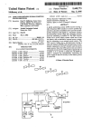
[1'75
IF
1
to
I
DETECTOR
70
physician’s office or clinic by persons not requiring high
skill and training is described.
50 Claims, 10 Drawing Sheets
i
5
1’
l
l
I
1
FL
|4f__
50
I
,/ REGULATOR
:
1
\
Me
' g
ERMA
MD M
80
lllllllllll
l
QQ/QQ
902
051501012
FILTER
"
SAHPLEOUl
1
VAPOR
\
/l\
-— 4mg 1
ammo
45
Md
lNFANT BREATH
20
SAMPLE
[N
\[
[60
‘\
SAMPLING TUBE
HYDROPHOBIC
FILTER
l2
US. Patent
Mar. 15, 1994
Sheet 7 of 10
5,293,875
g!
2m
Q
$32513.:
@\h~:Es2.5:
MN
n;
2:
A5918
:1
(2%
. o2
S.
:52m
>2.T1.
US. Patent
Mar. 15, 1994
M3259 52o:
L+
{ES
22E:255g3
Sheet 8 of 10
5,293,875
US. Patent
Mar. 15, 1994
Sheet 9 of 10
5,293,875
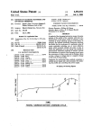
1.25
0.50
‘'00
_
0.00 Ni
"0.25
*2
F/6Z 3A
"HE —-
I25
050
0.00
F/G. 35’
C02 CONCENTRAHON OP.
8 * xvi/32M
EQUIVALENT C02 SENSOR RESPONSE
C0 CONCENYRATION 0R IDEAL C0 SENSOR RESPONSE
nco
U001
55 ?jv _
co
U002
U005
_
T5
US. Patent
Mar. 15, 1994
Sheet 10 of 10
5,293,875
600
SPIROMETER
‘:5
I
izo
500
l
90‘
1
END TIDAL ‘
IMPEDANCE
PNEUMOGRAPH
C0 MONITOR
75
l
1
5,293,875
IN-VIVO MEASUREMENT OF END-TIDAL
CARBON MONOXIDE CONCENTRATION
APPARATUS AND METHODS
A portion of the disclosure of this patent document
contains material which is subject to copyright protec
tion. The copyright owner has no objection to the fac
simile reproduction by anyone of the patent disclosure,
as it appears in the Patent and Trademark Office patent
?les or records, but otherwise reserves all copyright
rights whatsoever.
FIELD OF THE INVENTION
This invention relates to methods and apparatus for
in-vivo, real time measurement of end-tidal carbon
monoxide concentration in the exhaled breath, more
particularly the determination of end-tidal carbon mon
oxide concentration in the breath of a newborn infant.
BACKGROUND OF THE INVENTION
2
ment to analyze the acquired sample. In addition, this
technique requires time and personnel to transport the
sample from the patient to the laboratory (or equip
ment) where the analysis is conducted, and then to
report back to the attending physician/practitioner for a
diagnosis and prescription, if any.
Another problem with this technique is that accurate
assessment of the concentration difference in carbon
monoxide requires obtaining good samples of end-tidal
patient breath. This essentially requires that the patient
have a regular, predictable breathing cycle. Thus, it can
be difficult to obtain a good sample by watching chest
wall movement, particularly for a newborn and for
patients having irregular breathing cycles.
Chemical electrochemical sensors capable of measur
ing carbon monoxide concentrations in the range of
interest, 0 to 500 parts per million (ppm), are commer
cially available, e.g., model DragerSensor CO available
from Dragerwerk, Lubeck, Germany. However, such
20 sensors are sensitive to many other gases as well as
In most animal systems, carbon monoxide is a waste
carbon monoxide, and are therefore susceptible to er
ror. Another problem with such sensors is that the mea
product produced in the breakdown of free hemoglobin
within the blood. Ordinarily, hemoglobin is contained
surement dynamics of the sample gas transport through
the gas permeable membrane and oxidation-reduction in
within red blood cells and is stable. However, aging of 25 the electrochemical cell results in a relatively slow
red blood cells and certain disease processes produce
response time such that discrete samples of the end-tidal
hemolysis, i.e., the breakdown of the cell wall. This
breath must be obtained and analyzed to determine the
produces free hemoglobin which breaks down in the
end-tidal carbon monoxide concentration.
blood. The carbon monoxide that is produced by the
breakdown of free hemoglobin is normally excreted in
the breath.
When the system is in equilibrium, the carbon monox
ide concentration in the breath is proportional to the
difference in the concentration of carbon monoxide in
SUMMARY OF THE INVENTION
It is, therefore, an object of the present invention to
provide improved non-invasive apparatus and methods
for measuring carbon monoxide concentration in the
end-tidal breath. It is another object to provide appara
the blood and the concentration of carbon monoxide in 35 tus and methods that operate in real-time. It is another
room air. This difference in concentration is propor
object to provide apparatus and methods for use in
tional to the rate of hemolysis in the blood.
determining the rate of hemolysis from the concentra
The concentration of carbon monoxide in the end
tion of end-tidal carbon monoxide.
tidal breath, i.e., the gas that is last expelled each breath,
It is another object of the present invention to pro
is presumed to be at equilibrium with the concentration
vide apparatus and methods for measuring end-tidal
in the blood. This is because the end-tidal breath con
carbon monoxide that do not require a highly skilled,
tains predominantly, if not exclusively, the gas expelled
trained individual to obtain and determine the measure.
from the alveoli in the lungs, which gas was within the
It is another object to provide such apparatus and meth
alveoli for a time generally sufficient to equilibrate with
ods that do not require incrementally acquiring samples
the blood.
45 of end-tidal breath during successive respiratory cycles.
It is known that hemolysis and the resulting by
It is another object of the invention to provide a
products and consequences of hemolysis can be esti
portable, easy-to-use apparatus that can be used in a
mated or predicted from a measure of the concentration
nursery, a physician's office, a hospital, a clinic, and a
of carbon monoxide in the end-tidal breath. See Smith,
mobile clinic for measuring end-tidal carbon monoxide
D. W. et al., “Neonatal Bilirubin Production Estimated 50 in real-time, for assessing the likelihood of elevated
from End-Tidal Carbon Monoxide Concentration”,
levels of hemolysis for immediate entry on the patient’s
Journal of Pediatric Gastroenterologz and Nutrition,
3:77-80, 1984.
One method of analysis previously reported includes
incrementally acquiring a sample of end-tidal breath
and analyzing the acquired sample by mass spectros
record and prescription of an appropriate remedy.
In accordance with this invention, there is provided
an apparatus, sampling methods, and analysis tech
55 niques for measuring the concentration of end-tidal
carbon monoxide in breath, particularly in newborn and
copy or gas chromatography to determine the end-tidal
carbon monoxide concentration. The sample is obtained
by extracting from each of several successive breaths a
premature infants. Broadly, the invention concerns de
termining the concentration of end-tidal carbon monox
ide based on a measure of the room air carbon monoxide
concentration, a measure of the average carbon monox
portion of the apparent end-tidal breath using a syringe.
The end-tidal portion of breath is determined by observ
ing the chest movements ofthe'infant. See, e.g., Vreman
ide concentration for a breath sample over a period of
time, and a determined ratio of the end-tidal breath to
et al. US. Pat. No. 4,831,024.
inspired air for the sampled portion.
One problem With this technique is that it requires a
The present invention is based in part on the discov
skilled, trained user to obtain the end-tidal sample in 65 ery that accurate assessment of end-tidal carbon monox
successive increments based on watching chest wall
ide concentration may be obtained based on knowledge
movements. 11 also requires a trained, skilled person to
of the fraction of the gas sample that is end-tidal gas.
operate a complex piece of analytical laboratory equip
Thus. the present invention is able to avoid selectively
3
5,293,875
4
FIG. 1 is a schematic block diagram of an apparatus
sampling small samples of end-tidal breath over succes
for determining end-tidal carbon monoxide concentra
tion in accordance with the present invention;
FIG. 2 is a diagram of a multipurpose microcon
troller board for controlling the device in FIG. 1;
sive respiratory cycles to obtain a suf?ciently large
end-tidal breath sample, which incremental sampling is
problematic. Further, the invention advantageously
uses a conventional carbon monoxide detector, which
has a response time that is not fast enough to distinguish
carbon monoxide in end-tidal breath from carbon mon
FIGS. 2A-2D are macro ?ow diagrams for the over
all, breath measurements, calibration, and data commu
nication operations of the apparatus of FIG. 1;
oxide in inspired air, to derive the end-tidal carbon
monoxide concentration in real-time. More particularly,
a conventional carbon monoxide detector can be used
to obtain the average carbon monoxide concentration
FIGS. 2E and 2F are circuit schematic diagrams for
a signal conditioning ampli?er and a power supply re
spectively, for interfacing the carbon monoxide sensor
level during breathing, which average value can be
related to the end-tidal value based on the determined
2;
of FIG. 1 and the microcontroller circuit board of FIG.
FIGS. 3A and 3B are graphical illustrations of mea
surements of carbon monoxide carbon dioxide concen
ratio of end-tidal to inspired breath. Preferably, the
most common interfering substances from a sampled
breath are removed from the sample by a consumable
?ltration medium so that these substances do not affect
the measurement. The present invention also applies to
gas components of exhaled breath other than carbon
trations acquired using the device of FIG. 1; and
FIGS. 4A and 4B are graphical illustrations of the
carbon monoxide and carbon dioxide concentrations in
a representative breath flow; and
FIG. 5 is a schematic block diagram of an apparatus
for determining end-tidal carbon monoxide concentra
tion in accordance with alternate embodiments of the
monoxide, which gas components cannot be directly
monitored because of the slow response time of avail
able gas detectors.
present invention.
One aspect of the present invention concerns using a
second gas component of the breath, other than the ?rst 25
DETAILED DESCRIPTION OF THE
INVENTION
gas component whose concentration is being moni
tored, to determine the ratio of the end~tidal breath to
Referring to FIG. 1, a preferred embodiment of the
inspired air. The relative concentration level of the
present invention relates to methods and apparatus for
second gas during respiration is monitored and the ratio
monitoring breath flow of a patient over a period of
or duty cycle of the end-tidal portion of the sensed 30 time and determining the end-tidal concentration of
concentration waveform relative to the inspired air is
carbon monoxide in the breath. The apparatus includes
determined. A sensor for detecting the level (or concen
a nasal cannula 10, a carbon dioxide detector 30, an
tration) of the second gas having a time response that is
organic vapor ?lter 45, a flow regulator 50, a pump 60,
fast enough to distinguish the end-tidal breath concen
a carbon monoxide detector 70, and a microcontroller
tration from the inspired air is preferably used. One 35 80. Preferably, a hydrophobic ?lter 15 is provided be
suitable gas component is carbon dioxide, which has a
tween the cannula 10 and the gas detectors to remove
large, distinctive change in concentration with breath
ing. Other gases may be used, e.g., hydrogen, oxygen,
moisture from the sample of breath. In particular, ?lter
or some combination of gases, e.g., carbon dioxide and
tecting carbon dioxide. Filter 15 is illustrated in FIG. 1
15 is used so that moisture does not interfere with de
hydrogen.
as inserted between tube 140, which includes cannula
10, and a connector 16a, which is secured to the base 5
The determined end-tidal carbon monoxide concen
tration may be used by a physician or other suitable
health care provider to evaluate the rate or relative
level of hemolysis occurring in the infant. The evalua
tion is typically made by comparing the determined
end-tidal carbon monoxide concentration to known or
which supports and preferably encloses the gas detec
tors 30 and 70, pump 60, and flow regulator 50. One
45
suitable hydrophobic ?lter 15 is part number 51190,
available from Filtertek, Inc.
Cannula 10 is one segment of tubing 14a which has
preselected standards. For example, when measured
one end 11 that is adapted for insertion into the nostril
soon after birth, the end-tidal carbon monoxide range
(posterior nasal pharynx) of a normally breathing pa
0.6—l.9 ul/l is considered normal and the range above
tient, e.g., an infant. End 11 has at least one aperture 12
about 2 [.Ll/l is considered at risk. Premature infants 50 for extracting a sample of the exhaled breath as de
have both a higher risk of neonatal jaundice and a
scribed below. Preferably, end 11 has a length and an
higher normal range of end-tidal carbon monoxide.
inner and outer diameter appropriate for insertion into
The present invention provides a tool for predicting
the patient’s nostril, tag, a 3.0 cm length of tubing hav
the likelihood that the determined level of hemolysis
ing an inner diameter on the order of 1.0 to 1.5 mm and
will lead to adverse consequences, such as jaundice and 55 an outer diameter of 2-3 mm, and a sufficient number of
hyperbilirubinemia, which might not appear for several
days. Thus, the apparatus and methods of the present
invention provide for reliable detection and early treat
holes 12 perforating the tube circumference for receiv
ing a sample of breath. The dimensions may be adjusted
for the size of the patient. The length of cannula 10 is
ment of the condition by an appropriate remedy, and for
monitoring the ef?cacy of the treatment.
sufficient to extend from the base 5 to the patient, and is
typically on the order of 75 to 100 cm.
BRIEF DESCRIPTION OF THE DRAWINGS
The above and other objects and advantages of the
invention will be apparent upon consideration of the
14g are used to form the flow path between the various
elements of the apparatus as shown in FIG. 1. The tube
segments may be made of, for example. medical grade
following detailed description taken in conjunction
catheter tubing, polyethylene, polypropylene or vinyl.
Segments of tubing 14a. 14b, 14c. 140'. 14e, 14f and
with the accompanying drawings, in which like refer
The ends of the segments are typically frictionally fitted
ence characters refer to like parts throughout, and in
which:
over bosses of connectors 16 and the various compo
nents as shown in FIG. 1 and may be clamped for a
5
5,293,875
6
through an infrared absorption-type carbon dioxide
more secure interconnection. Connectors 16a, 16b, and
16c are preferably mounted in the same region of base 5
to allow for easy access for replacement of the cannula
detector prior to an electrochemical cell type carbon
monoxide detector. In addition the use of an exhaled gas
(carbon dioxide or another) provides a non intrusive
and ?lters.
Cannula 10 is connected at its other end in series with
?lter 15, connector 160, a second length of tubing 14b
and the input port 20 of a carbon dioxide detector 30.
Detector 30 has a gas sample cell and is used to provide
a signal corresponding to the sensed concentration of
and non invasive technique for determining the duty
cycle dc. It does not require an additional or alternate
sensor or transducer on or near the patient and it does
not require additional patient cooperation or discom
fort. Furthermore, using one time-sample of breath to
carbon dioxide in the gas. The detector 30 has a re
determine the duty cycle of end-tidal breath is more
accurate than visually monitoring chest wall movement
or respiratory activity over a period of breathing cycles,
sponse time that is suf?ciently fast to distinguish the
concentration level of the end-tidal portion from the
other portions of the breath. Thus, the signal changes in
or relying on a predetermined breathing rate, which are
response to changes in the concentration of carbon
subject to change, and attempting to obtain samples of
dioxide in the breath as the patient breathes. The resul 5 exhaled breath only during end-tidal portions.
tant signal waveform is used, as described below, to
Other gas sensors may be used, e.g., oxygen which
determine the ratio of the end-tidal portion of the breath
would have a relatively reduced concentration level
to the entire inspired air. This ratio, referred to as the
during end-tidal breath, or hydrogen, which would
duty cycle (“dc”) is used to convert the detected carbon
have a relatively increased concentration level during
monoxide concentration (“CO”) to the end-tidal carbon
end-tidal breath. Two different gas detectors, e. g., car
monoxide concentration (“C0157”), as described below.
bon dioxide and hydrogen, could be used to identify the
One suitable carbon dioxide gas analyzer is the com
end-tidal portion, wherein carbon dioxide provides a
mercially available Servomex model 1505 fast response
fast response and hydrogen provides a slow response to
carbon dioxide infrared transducer, which is available
changes in concentration.
from Servomex Company, 90 Kerry Place, Norwood,
Mass. 02062. This device is a temperature compensated,
sealed transducer that is based upon a single beam, sin
gle wavelength technique absorption for measuring
carbon dioxide. It has a complete optical bench and uses
a fast infra-red carrier which is attenuated by the infra
red absorption of carbon dioxide in the gas. The device
has detection circuitry that will convert fast changes of
attenuation into an electrical output signal.
The Servomex model 1505 transducer is used in ac
cordance with the manufacturers directions and speci?
cations. It provides, under constant conditions, a linear
output voltage of from 0 to 1.0 volts corresponding to
from 0 to 10% carbon dioxide, and is extendable up to
1.5 volts corresponding to 15% carbon dioxide. The
response time is on the order of 120 ms at a flow of 100
ml/min, and the flow rates may be in the range of from
25
Another advantage of the invention with respect to
relying on changes in gas concentration levels is that the
measurement decouples the breath gas concentrations
from rhythmic respiratory activity. In other words,
pump 60 may be used to provide a gas flow rate through
cannula 10 and the flow path that is greater than the
patient‘s respiratory flow. This, in turn, provides an
end-tidal “waveform” stretching that enhances evalua
tion of the gas concentrations and determination of the
end-tidal portion of the breath based on a breath gas. It
also provides for synchronization between the respira
tory activity corresponding to the end-tidal portion
based on carbon dioxide and the detection of carbon
monoxide concentration in the same breath sample
flow. Consequently, the carbon monoxide concentra
tion may be calculated based on post data acquisition
50-200 ml/min. Other carbon dioxide measuring de
vices also could be used.
It should be understood that any device that is capa
processing analysis of the last acquired sample. As a
result, the end-tidal carbon monoxide determination is
effectively provided in real-time and without the delay
flow velocity or flow volume, a non breath ?ow device
not.
500 for monitoring breathing, e.g., an impedance pneu
mograph, a microphone sensor, and the like. See FIG.
5, which shows the conventional locations of spirome
nected to a piece of tubing 14c and passed through
55 connector 16b into tube segment 14d. Tube segment 140'
ter 600 and an impedance pneumograph type non ?ow
breath monitor 500, the latter of which surrounds the
contains an organic vapor ?lter 45. Filter 45 may con
tain any medium that will absorb organic vapors and
patient‘s body to produce a signal that varies as the
patient’s body varies with breathing. Also, a breath gas
bon monoxide levels in the carbon monoxide detector
ble of determining the duty cycle of end-tidal breath to 45 occasioned by the previously reported techniques. In
addition, the present invention avoids reliance on a
inspired air over a given period of time may be used in
previously established breathing cycle or rate to predict
place of the carbon dioxide detector, provided that the
when chest wall movement coincides with end-tidal
determined duty cycle is for the same period of time
?ow. Instead, the invention is completely responsive to
during which the sample on which the carbon monox
changes in the patient‘s breathing rate and volume as
ide concentration determination is basedwas acquired.
the sample is acquired. The prior known techniques are
Such a device may be a spirometer 600 for measuring
The gas ?ow output 40 of detector 30 is in turn con
reducing gases that might interfere with detecting car
detector for monitoring a breath gas other than carbon
dioxide may be used.
10.
The carbon dioxide detector is preferred because
changes in CO2 concentrations related to end-tidal flow
are relatively large and easily detectable using a thresh
old level of carbon dioxide. Further. the same sample of
preferably constructed as a canister that either can be
breath can be used to determine the carbon monoxide
and carbon dioxide concentrations without affecting the
sample, particularly when the sample stream is passed
Filter 45 preferably contains activated charcoal. It is
inserted interior to the flow path of tube 14d or is in
serted between two segments of tubing such that the
analyte gas stream passes through the canister. Filter 45
illustrated in FIG. 1 connected between two connectors
16!) and 160 so that it is external to base 5. This provides
for simple and quick replacement of ?lter 45 when it is
7
5,293,875
8
substantially consumed. Filter 45 may be an inexpensive
reference electrodes. The carbon monoxide in the gas is
disposable portion of the apparatus.
electrochemically converted at the sensing electrode,
One advantage to using ?lter 45 is that it tends to
average the concentrations of gas in the analyte stream
by thoroughly mixing the stream within the volume of
monoxide partial pressure. The device is temperature
which produces a current proportional to the carbon
compensated. It has a concentration sensitivity in the
range up to 500 ppm and provides an output current of
0.13:0.4 uA/ppm, and requires about 20 seconds to
?lter 45. A preferred construction of ?lter 45 is to use a
20 mm length of charcoal rod having a circumference
of 24.4 mm which is sandwiched between 3.0 mm seg
ments of white acetate having the same circumference.
The charcoal rod is preferably cut from Filtrona AAD
equilibrate fully with the gas sample being monitored; it
has a reaction half life of ten seconds.
Microcontroller 80 is used to control the operation of
the apparatus. Microcontroller 80 receives signals re
Charcoal Filter Rods, available from American Filtrona
Corp., Richmond, Va. Where desired, more than one
lated to the output signals from carbon dioxide detector
30 and carbon monoxide detector 70, corresponding to
carbon rod segment may be used, provided that pump
60 has sufficient power to pass the analyte gas stream
therethrough.
Flow regulator 50 and pump 60 are inserted, prefera~
bly in tandem as illustrated in FIG. 1, into or between
segments of tubing 14 to maintain a desired constant
15
the sensed instantaneous carbon dioxide concentration
and sensed average carbon monoxide concentration,
respectively. These received signals are processed to
compute a value corresponding to the end-tidal carbon
monoxide concentration in the patient’s breath, as de
flow velocity of the analyte stream. Flow regulator 50 is
scribed below. The computed value may then be dis
interposed between tubing 14e, which is connected to 20 played on a display 90, such as a liquid crystal display
device.
connector 160, and tubing 14f which is connected to
Preferably, a conventional digital microcontroller
pump 60. Pump 60 is in turn interposed between tubing system is used having a suitable software-controlled
14f and tubing 14g, which is connected to carbon mon
oxide detector 70.
microprocessor, memory, analog to digital conversion,
Preferably, pump 60 and ?ow regulator 50 are ad 25 and signal conditioning functions. Of course, as will be
justed so that the flow is maintained at from 40 to 60
ml/min, more preferably 50 ml/min. This provides for
withdrawing continuously a gas sample, either from
room air or from the patient’s posterior nasal pharynx,
depending on placement of the cannula 10, including
expired and end-tidal breath for patients having a
breathing rate of from 10 to 90 breaths per minute. The
flow regulator 50 provides for limiting the flow rate of
the analyte gas stream, and the pump 60 provides for
sampling the gas sample (room air or breath) such that
pump 60 is driven against the flow rate limit set by flow
regulator 50. This maintains a constant ?ow rate for the
analyte stream, and avoids any ?ow surges due to a
apparent to persons of ordinary skill in the art, discrete
analog circuit elements and solid state ?nite state ma
chines also may be used to control the operation of the
elements and obtain the concentration measurement.
One suitable digital microcontroller is the model
Little Giant LG-X miniature microcontroller, available
from Z World Engineering, Davis, Calif. The mi
crocontroller 80 is connected to carbon dioxide detec
tor 30, carbon monoxide detector 70, pump 60, and flow
regulator 50 (if one is used) to operate and/or receive
signals from those devices. An ampli?er interface cir
cuit 82 is used to provide for current to voltage conver
sion of the signals provided by carbon monoxide detec
tor 70.
patient’s inhalation or expiration. One suitable flow
regulator is ori?ce/needle valve model F-2822-4l-B80 40 Referring to FIG. 2B, interface circuit 82 includes
three ampli?ers, UlB, U28 and USB, which are prefera
55 available from Air Logic, Racine, Wis, which can be
adjusted to obtain the desired gas flow rate in the range
of 40-60 ml/min. One suitable pump is model NMP O2
bly OP-29O low-noise, dual operational ampli?ers avail
diaphragm micro pump, available from KNF Neu
berger, Inc, Princeton, N.J., which has a free flow ca
pacity of 0.22 to 0.55 L/min. Pump 60 and flow regula
Calif. Ampli?er UZB is con?gured as a current to volt
tor 50 may be located anywhere in the flow stream,
preferably between the carbon dioxide detector 30 and
carbon monoxide detector 70 inside the enclosure of
base 5. Pump 60 also passes the analyte flow stream out
exhaust 75, downstream of the gas detectors 30 and 70
of the apparatus.
Carbon monoxide detector 70 is preferably an elec
trochemical sensor that produces an electrical current
able from Precision Monolithics, Inc., Santa Clara,
age converter, having a 0.1 uf capacitor C3 in parallel
with a 50 k0 resistor R1 in the feedback loop. The gain
is determined by resistor R1.
Ampli?er UlB is a second order lowpass ?lter with
approximately a 0.5 second time constant, using two 470
k0 resistors R2 and R3 and two 1 uf capacitors C2 and
C3 con?gured as shown. The ?lter is used to attenuate
electrical noise.
Ampli?er U3B is con?gured as a simple ampli?er
with gain adjustment potentiometer R8 (100 K0) in
proportional to the concentration of reducing gases,
series with a 10 k0 resistor R7, both of which are in
such as carbon monoxide, which are present in the gas
parallel with a 0.1 pf capacitor C4 in the feedback loop.
and a 10 k0 input resistor R4 at the inverting ampli?er
at the gas permeable membrane of detector 70 (not
input. Potentiometer R8 is used to allow initial calibra
shown). The response time of the carbon monoxide
detector 70 and the averaging function of the ?lter 45
tion to compensate for sensitivity variations in gas de
preferably result in a signal output from the detector 70 60 tectors. Ampli?er USB also has a secondary input from
that is proportional to the average concentration of the
ampli?er UlA, which is con?gured as an adjustable
reducing gas at the membrane.
voltage source that may be used to compensate for a
One suitable carbon monoxide sensor is model Drag
zero gas output of detector 70.
,
Ampli?er USA is con?gured as a unity gain buffer
erSensor CO, available from Dragerwerke of Lubeck,
Germany. It has a plastic gas permeable membrane, a 65 designed to isolate the previous stages from any load
liquid electrolyte, sensing, reference, and counter elec
effects that may imposed by following circuitry.
trodes in the electrolyte. and a potentiostatic circuit that
maintains a constant voltage between the sensing and
Ampli?er U2A is con?gured as shown as an adjust
able bias source for the counter electrode ofdetector 70.
5,293,875
as determined by the setting of resistor R21, a 500 k0.
potentiometer. A 10 ,9. resistor R22 provides a means of
reading the bias voltage without making direct contact
with the gas detector connections. The CO detector
ampli?er circuit 82 operates as a low power supply
voltage to prevent excess leakage currents from impos
ing undesirable bias currents on the detector 70, and to
allow low power continuous biasing of the detector 70
to allow for stable operation. Preferably, ampli?ers
10
lar elements provided by the manufacturer which either
are used in a conventional manner although not perti
nent to the present invention, or are not used. The mi
crocontroller is used in accordance with the manufac
turer’s directions and speci?cations, except as otherwise
noted, and reference is made to the user manual for the
device, entitled “Little Giant Single Board Computer
Technical Manual Version E” which is available from
the manufacturer, for information regarding con?gur
ing and implementing use of the microcontroller.
The display device 90 is capable of providing a dis
nections are to a virtual ground, which is provided by a
play corresponding to the determined carbon monoxide
CO ampli?er power supply circuit 83.
concentration level in the end-tidal breath COET. Pref
erably, display 90 includes a display screen for alphanu
Referring to FIG. 2F, the CO ampli?er power supply
and interface circuit 83 is shown. The power supply 5 meric text, including the determined COET concentra
consists of a normal supply B1 and a backup supply B2.
tion, and preferably instructions to the operator for
operating the device to acquire the appropriate gas
Normal supply B1 may be any nominal +/—l2 volt
samples. Further, display device 90 is preferably user
DC power supply. In one preferred embodiment, nor
mal supply B1 is a regulated power supply derived from
interactive and includes both a keyboard for operator
input and a visual display for prompting the operator to
AC mains. Alternately, two 12 volt batteries, e.g., re
act. Also, the display device 90 may include a paper
chargable batteries, could be used.
Devices Q3 and Q4 are integrated circuit regulators
printer or have an associated printer (not shown) for
providing a printed copy of the parameters determined
(types LM78L05 and LM79L05) with provide +/—5
UZA and U3A also are type OP-29O ampli?ers. In the
circuits illustrated in FIGS. 2E and 2F, all ground con
volts respective, for powering the interface ampli?er
and/or measured, in character text or graphic form.
BUlA. Diodes D1 and D2 (IN4l48 type diodes) auto 25 Altemately, or in addition, audible sounds, visual indi
matically switch to supply to the CO ampli?er BUlA
cators or lights may be used to prompt the operator to
the greater of the normal 12 volt DC supply B111, and
perform the appropriate act.
the backup battery B2, an alkaline 9 volt battery.
One suitable display device is a model LG-LCD
Device Q1 regulates the supply voltage to +5 volts.
keypad liquid crystal display device, available from Z
Device Q2 is an integrated circuit virtual ground sup
ply, model TLE2425, available from Texas Instruments,
Dallas, Tex. Its output “splits” the ?ve volt input into a
World Engineering. This device has de?nable function
$2.5 volt supply with a virtual ground at 2.5 volts DC
keys on a keyboard and a visual character display. The
visual display includes a 2 line by 16 character LCD.
The keyboard has a 4 x 4 keypad and a beeper for key
“real” potential.
pad feedback. It is compatible with and directly inter
Ampli?er BUl of circuit 83 includes two type 1458 35 faces with the Little Giant LG-X miniature microcon
dual operational ampli?ers, BUlA and BUIB, available
from National Semiconductor, Santa Clara, Calif. Am
pli?er BUIB is con?gured as a differential ampli?er
with gain of l, and has inputs of the virtual ground from
the CO ampli?er circuit 82 and the CO ampli?er circuit
82 output. Resistors BR3 (120 kit) and capacitor BC3
(10 pi) provide further low pass ?ltering with a 1.2
second time constant. Ampli?er BUlA is con?gured as
a voltage follower with a low output impedance, for
troller.
I
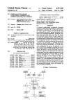
Referring to FIG. 2, a printed circuit board layout of
the Z World Little Giant microcontroller circuit board
is illustrated and the interconnection of elements is de
scribed, using the manufacture’s conventional pin con
nections (unless otherwise stated). Referring to terminal
board TBl, one or more AC-DC regulated power
supplies (not shown) are used to provide the following
signals to the four numbered input pins of terminal TB]:
driving the analog input on the Little Giant microcom 45 — 12 volts to pin 1, ground potential to pin 2, + 5 volts
to pin 3, and + 12 volts to pin 4. The corresponding four
puter board 80.
Referring to FIG. 2, the Little Giant LG-X mi
output pins of terminal board TB], designated TBl-X’
crocontroller 80 is programmable using Z-World’s Dy
wherein “X” refers to the output pin, are respectively
connected in series with the input pins of TBI and the
namic C language. It uses about 200 mA, contains a
microprocessor Z180 having a 9.216 MHz clock fre
pins of the apparatus illustrated in FIG. 1 as follows.
quency and sufficient memory including read only
Regarding microcontroller 80, the high current out
put wiring connectors J1 have pin J 1-8 connected to the
memory ROM, random access memory RAM, and
erasable, programmable read only memory EPROM,
negative terminal of pump 60 for providing a current to
drive pump 60 at the selected rate. There are no other
which collectively contain the software, data, and mem
ory address locations for operating the apparatus, pro 55 connections for wiring connectors J1. The power wir
ing connectors J2 have pin J2-1 connected to J24, pin
cessing the acquired data, and performing the data ma
J2-2 connected to J2-3, pin J2-6 connected to "IE1
nipulation and post acquisition processing functions in
accordance with the present invention, as described
2'(ground), pin J2-7 connected to TB1-4’(+l2 v), and
no other J2 pin being connected. The RS485 ?eld wir
herein. The device also contains counter-timers, includ
ing a 2 Hz watchdog timer for automatically resetting
the microprocessor in the event of unde?ned operations
or temporary power loss, serial input/output ports,
parallel input/output ports, time and date clocks, multi
channel analog to digital converter, a digital to analog
converter, operational ampli?ers for input signal condi
tioning in single ended or double ended modes. adjust
able gain and input voltage ranges, a high current driver
output suitable for driving pump 60, and other particu
ing connectors J3 are not used in this embodiment.
The analog input ?eld wiring connectors J4 have pins
J4-1 and J4-2 connected to amplifier interface board
pins J2-1 and J2-2 respectively, pin J4‘3 connected to
pin PL4-1 on the Servomex 1505 board, and pin J4-4
65 connected to pin PL4-2 on the Servomex model 1505
board. Analog input pins J5, RS232 port pins J7, and
RS485 program pins J9 are not used. The pins at key
board interface J6 are used to connect a flat ribbon
11
5,293,875
12
cable to the back panel of the display 90, LCD display
device model LG-LCD. The pins 18 for the RS232 port
apparatus. Button #1 is a start button to initiate some
are connected on the back panel to a conventional nine
pin D-sub connector. The display 90 interface pins 110
button #2 is a reset button, button #3 is a select button
to select some option from a menu, and button #4 is a
are connected as ‘follows. Pin 110-10 are the common
menu button to display one or more instruction and/or
front panel buttons; pin 110-12 is for button #1, pin
operation menu. Each button is activated by pressing in
and then releasing the button. Other alternatives for
providing user input in an interactive device may, of
11014 is for button #2, pin 110-16 is for button #3, and
pin 110-18 is for button #4.
Regarding the Servomex model 1505 circuit board, it
is connected as follows. For device Power, pin PL1-1 is
connected to TBl-l’ (—l2 v), pin PL1-2 is not con
nected, pin PL1-3 is connected to TB1-2' (ground), pin
PL1-4 is connected to TB1-3’ (+5 v). For device
Thermistor Status, pins PL2 are not connected. For
device Nitrous Oxide Compensation, pins PL3-1 and
PL3-2 are jumpered and no other pins are connected.
action by the apparatus to reset the apparatus operation,
course, be used.
Referring to FIG. 2A, the device becomes activated
on power on or reset (pressing button #2) and enters an
initialization sequence at step 100. During initialization,
the operating code of microcontroller 80 is booted and
various system checks and device initializations are
performed. Following initialization, the routine passes
For device Signal Output, pins PL4-1 is connected to
Little Giant pin 14-3 and pin PIA-2 is connected to
to an idle state at step 110, where it waits for user input.
invention, the end-tidal carbon monoxide concentration
of the patient is measured in the following manner. An
initial value of carbon monoxide may be obtained for
analysis purposes. Pump 60 is then started and a sample
of room air is drawn through the segments of tubing
14a-l4g at the selected flow rate of, e.g., 50 ml/min,
past the carbon dioxide detector 30 and the carbon
monoxide detector 70. At the end of a ?rst time period,
e.g., 45 seconds, the measures of the concentrations of
the carbon dioxide and carbon monoxide in the sample
suring sequence. This passes the operating routine to
step 120.
Also during the idle state 110, the operator may press
During the idle state, the system preferably generates a
suitable message on display 90, e. g., “Ready, press 1 to
Little Giant board 14-4. For device Remote Calibration
start”. Thus, during the idle step 110, the user may
Adjustment, there are no pin connections.
20 provide an input by pressing button #1 to start a mea
According to a preferred embodiment of the present
cells of the carbon dioxide sensor 30 and carbon monox
ide sensor 70 are obtained, respectively. The measures
are obtained as analog signals from the detectors 70 and
30, e.g., sensed currents converted to conditioned volt
ages vco and vcoz, which are respectively digitized into
button #3 to select a sequence from a menu displayed
on the display unit 90, and button #4 to display various
operation sequences. One such sequence is a calibration
routine for calibrating the carbon monoxide detector 70
and carbon dioxide detector 30 at step 130. The opera
tor also may press button #2 at any time to exit what
ever routine it is executing, reset the apparatus, and
return the routine to step 100.
Referring to FIGS. 2A and 2B, in response to press
ing button #1 in the idle state 110, the routine moves
35 from the idle step 110 to step 120 for the sequence for
determining end-tidal carbon monoxide concentration
n-bit words (n is preferably 8) at selected sampling rates
COET. There are three phases to this determination, a
and passed into a data buffer and/or memory. The val
sequence at step 121 for measuring the background
carbon monoxide COM,” during a ?rst time period, a
ues are stored as COM,m and COzzm.
Pump 60 is then turned off and the cannula 10 is
placed in the patient’s nostril, preferably in the posterior
pause or delay period at step 122, and a sequence at step
123 for measuring breath carbon dioxide CO2 and car
bon monoxide CO during a second time period.
nasal pharynx. Then the pump 60 is turned on again and
an analyte stream of breath is drawn past the respective
In the present invention, before each sample is ob
gas detectors 70 and 30. The concentrations of carbon
tained, pump 60 is off for a delay time period. This
monoxide and carbon dioxide are respectively sensed
allows the CO detector to return to a zero state so that
and sampled during a second time period, e.g., 45 sec
effectively no CO is in the sample cell. When desired, a
ends.
supply of inert gas may be provided and pump 60 acti
The acquired measures of the carbon dioxide concen
vated for a time to clear the sample cell of any CO (and
tration over the second time period are evaluated. First,
CO2) gas. A three-way valve and an actuator may be
the relative‘changes in the carbon dioxide concentration
included (not shown) to achieve this cell clearing func
are evaluated to determine the duty cycle correspond 50 tion. The delay time period is at least about one minute,
ing to the end-tidal portion of the patient’s breath. An
more preferably three minutes.
average of the end-tidal CO, concentration ("COM-T”)
In the background measurement sequence step 121,
to the average CO2 is obtained, providing the duty
the user is prompted to place the end 11 of cannula 10
cycle dc.
somewhere in the vicinity of the patient, but not inside
The end tidal CO concentration (“COET”) is then
the nostril and then to press button #1. In response to
determined from the following relationship:
pressing button #1, pump 60 is activated at time to and
the background room air is drawn through tubing 14
C057: lcomean_corooml/dc
(1)
and during a ?rst time period of approximately 45 sec
where COMM is the average or mean carbon monoxide
onds. During this time, display 90 preferably displays a
concentration at the end of the second period, and do is
suitable message corresponding to the duration of the
background measuring test, e.g., how much time re
mains to complete the test, in seconds or in percent.
At time t1 at the end of the ?rst time period. pump 60
the duty cycle determined for C0251.
Referring to FIG. 1, the macro flow diagrams of
FIGS. 2A to 2D, and the software appendix attached
hereto, a preferred embodiment of the operation of the
present invention is now described, In this embodiment,
display device 90 is con?gured to use four buttons
which are used for controlling the operation of the
. is turned off. The carbon monoxide concentration in the
sample cell of the carbon monoxide detector 70 is then
determined and recorded in memory as COMM. As
noted, the carbon monoxide gas detector has a time
13
5,293,875
response to the analyte ?ow that produces an average
carbon monoxide concentration. As set forth in the
14
software appendix hereto, the digitized samples corre
tained for analytical purposes. During this second time
period, the display 90 preferably displays a suitable
message corresponding to the duration of the measuring
sponding to the carbon monoxide concentration are
processed so that the output signal is the average of the
in seconds or in percent. At time t3, at the end of the
test, e.g., how much time remains to complete the test,
last ?ve acquired samples. Preferably the determined
second time period, pump 60 is turned off.
During the second time period, the signals corre
concentration value is displayed, e.g., in parts per mil
lion (ppm). The amplitude of the voltage signal v00,
sponding to the CO; concentration obtained from C0;
detector 30 are acquired. The relative changes in CO;
corresponding to the averaged sensed carbon monoxide
concentration comm from detector 70 that is dis
played, also may be displayed for diagnostic purposes.
concentration over time are then used to calculate the
duty cycle dc of the patient’s end-tidal breath. Prefera
bly, the signal corresponding to the carbon dioxide
The CO and CO2 gas equations used to convert the
sampled voltage signals corresponding to the detector
concentration is periodically sampled, e.g., the analog
signal outputs to gas concentrations are:
15
CO1% =m2 v¢m+c2,
signal is digitized at a ?rst sampling rate, e.g., 30 Hz
during the second time period. These samples are stored
in a data buffer for post data acquisition processing and
analysis.
(3)
Also, the signals corresponding to the CO concentra
tions obtained from detector 70 are acquired during the
where m1 and c1 are the slope and intercept calibration
second time period. Preferably, the carbon monoxide
concentration is periodically sampled, e.g., the analog
signal is digitized at a sampling rate of 1.0 Hz during the
constants relating the voltage vco derived from the CO
detector 70 output in response to the concentration of
carbon monoxide in a sample to ppm, and m; and c; are
the slope and intercept calibration constants relating the
voltage vcaz derived from the CO2 detector 30 output
second time period. These samples also are stored in the
data buffer for analysis.
in response to the carbon dioxide concentration in a
FIGS. 3a and 3b illustrate representative sampled
sample, in percent.
waveforms of the signals vco and Vcog provided by the
Thus, at time to, with CO=O ppm, using the above
CO and CO2 detectors 70 and 30 respectively, during a
equation:
second time period. The waveforms thus display the
30 concentration levels sensed corresponding to the cali
0=m1 vc0+c1 and
(2.1)
brated CO and CO2 levels. In these representative
drawings, the calibration functions were:
CO ppm: l2.ll RIO-+0.95; and
where vc0_0 corresponds to the signal produced by
35
CO detector 70 at time to. At time t1,
C0mmppm = m1Vc0_i + :1.
= mlVco-t — miVco-o
= mi(Vc0-1 — Vco-o)
(2.3)
(2-4)
(25)
where vc0_1 corresponds to the signal produced by
CO detector 70 at time t1.
When pump 60 is stopped at time t1 at the conclusion
(102% =1 1.96 vcgg+0.
The calculated duty cycle dc was 42.30%, the CD57
was 2.10 ppm, the COROOM was 2.01 ppm, the vc0._0
was ~O.78 v and the vc0_1 was 0.088 v. The vco min
was —0.05 v and the vco max was 0.17 v (correspond
ing also to the start (t2) and stop (t3) measurement volt
ages). The maximum vcoz was about 0.42 volts.
The 30 Hz sampling rate of CO2 was selected because
of the background step 121, the CO is measured and the
routine enters pause step 122. During the pause step 122, 45 it corresponds to the anatomical waveform of respira
tion from which the ratio of the end-tidal portion to the
the operator is prompted to place the nasal cannula 10
total air can be derived. The CO; sensor time response
inside the patient's nostril and then to press button #1 to
of 120 ms gives adequate resolution without acquiring
resume the measurement sequence. The system prefera
excessive data. The sampling rate of 1 Hz for the CO
bly displays a suitable message on display 90, e.g.,
detector voltage VCO was selected because the CO
“place nasal cannula”, to prompt the user to place the
detector has a much slower response time (the half time
cannula 10. The pause step 122 preferably includes a
of the CO response is about ten seconds) which cannot
minimum delay period Timeout of about ten seconds
discriminate the end-tidal portions and room air. Sam
and a maximum delay period Timeout of about ?ve
pling at a higher rate would not signi?cantly improve
minutes. Thus, if the operator does not press the start
the data resolution. The selected rates were selected as
button #1 within the Timeout period, the system will
compromises between collecting sufficient data with
return to the idle state 110. The Timeout period is used
adequate resolution in view of the sensor response time,
to provide for sampling the room air and patient carbon
and may be changed according to the sensors used and
monoxide concentrations within a time period wherein
the particular conditions of use.
it is not likely that the room air concentration level will
change very much. The Timeout period also is selected 60 Following acquisition of the data, the data is pro
cessed by the microprocessor Z180 of microcontroller
to permit the operator suf?cient time to insert the nasal
cannula 10 in a patient, such as a newborn infant, which
80 to derive the duty cycle and the end-tidal CO con
may require some time to accomplish.
Once the cannula 10 is place. the operator presses
centration COET. The digitized samples of the voltage
v50 are passed through a low pass digital ?lter, imple
button #1 to resume the measurement sequence 123. At 65 mented in the software, which takes an average of the
time t;, pump 60 is turned on for a second time period,
which is preferably the same as the ?rst time period. i.e.,
45 seconds. Initial CO and CO1 samples may be ob
last ?ve samples. This ?lter is used to suppress noise. It
also advantageously permits use of the output of the
digital ?lter without further averaging or storage of
5,293,875
15
COmmn=m1 Vm+C1.
16
Therefore, to obtain the patient’s actual end-tidal CO
separate values. The corresponding average or mean
CO concentration at time t3, COMM, is thus
level produced, the portion of the patient’s breath from
the COM". concentration (i.e., the CO level that was
inhaled by the patient) must be subtracted from the
(4)
total, which yields the equation (1) above.
where Vm is the average of the last ?ve voltage samples
The determined values are then displayed on display
90 and any desired printouts of the acquired data may be
VCO.
The duty cycle do is calculated based on analysis of
made or stored to a memory device or medium for
the sampled voltages vcoz between time t; and t3, as
subsequent analysis, as desired. The routine then exits
follows:
10 the measuring sequence 120 and returns to the idle state
dc
at 110. The display preferably include the determined
COET, e.g., in ppm, and also may provide the duty cycle
[the number of CO; samples > V,]
[total number of CO2 samples]
of the carbon dioxide waveform corresponding to the
end-tidal portion, and/or various voltages from the
[the number of CO2 samples > 1.5%]
[total number of CO2 samples]
detectors 30 and 70, such as minimum and maximum
voltages corresponding to CO and CO2, and initial and
?nal voltages for COW,"l and/or CO2 during the second
where V, is a selected threshold voltage corresponding
time period. It is noted that, in connection with the
to, e. g., a 1.5% CO; concentration, and is obtained from
second time period for monitoring the patient’s breath
the CO2 gas equation (3) as follows:
20 ing, the time references to and t1 may be used in place of
time references t2 and t3 respectively.
Preferably, the data from the measurement cycle just
?nished will remain displayed for a period of time to
allow the operator to record manually the data. The
For an ideal CO2 detector 70, mg: 10 and c2=0, such
that V,=0.l5 volts. Of course, other values and thresh
25
display 90 may be cleared by pressing button #1 (or
reset #2). Following measurement of a sample, the
aforementioned delay time period of about one minute
(or three minutes) is provided to allow the CO and CO2
old voltages could be used as appropriate in the particu
lar circumstances.
detectors 70 and 30 to decay to a “zero” state before the
Then, the patient’s end-tidal CO concentration COET
next background measurement cycle begins. Preferably,
1s:
any attempt to obtain another measurement before the
COET= (comean-coroam)/dc-
end of the delay period will be simply delayed until the
expiration of that time, and then automatically com
(I)
This may be calculated in a straightforward manner
from the acquired data.
The foregoing equations are based on the realization
that the physical behavior of CO and C0; are very
similar with respect to, for example, diffusion, flow
rates and other behavior characteristics in the patient’s
cardiopulmonary system. Accordingly, it can be as
sumed that ratio ofthe end-tidal CO2 portion to the total
CO2 portion is the same as the ratio of the end-tidal CO
portion to the total CO portion. This is illustrated in
FIGS. 40 and 48. Further, it can be assumed that the
CO3 concentration of room air is approximately 0 and
that the end-tidal CO; concentration is related to the
duty cycle of the breath waveform and the mean value
of the CO; concentration, namely:
mence.
35
Referring to FIGS. 2A and 2C, the CO and CO2
detectors 70 and 30 are periodically calibrated using
conventional CO and CO1 gases having known concen
trations. To begin the calibration sequence 130, the
system must be in the idle state 110. The operator then
presses button #4 to call the menu up on display 90. The
menu will display an appropriate message such as
“menu 1. Calibrate CO/CO2 sensor. Activate button
#1 to start”. The operator then presses button #1 which
begins the calibration sequence 130. The calibration
sequence involves the selection of test gases of known
concentrations, inputting the known concentration val
ues into the system during set-up sequence 131 for CO
and set-up sequence 133 for CO2, operating the pump 60
to draw the known gas into the system and determining
the signal level produced by the detector (30 or 70
depending on the gas; only one detector is calibrated at
a time) in response to the known gas concentration
Thus, based on these assumptions, the CO and CO2
during measurement sequence 132 for CO and measure
ratios are
ment sequence 134 for CO2.
55
In a preferred embodiment, the display 90 is used to
cozET - com,” _ comm/dc - o _
c057 _ comm
provide a sequence of instructions for the operator to
COZmean ~ Colmam _
COZmean - 0
— Comean — Comom
input data, such as which gas detector is to be calibrated
and the concentration of the test gas that is to be used
and thus
(sequences 13] and 133). This is followed by providing
a sample of that test gas, which is then sampled and
CO
— CO
(6)
l/dr = M
measured (sequences 132 and 134). Preferably, at least
two gas samples at different known concentrations are
used for each of CO and CO3. From these two samples.
and the total end~tidal COETis
the foregoing gas calibration equations (2) and (3) for
65 converting a provided voltage to a gas concentration
(COmPari —- Comm)
COET :
(7)
+ COmam
are determined. The calibration equations are reason
ably accurate over the concentration ranges of interest.
e.g., accurate within 10%.
17
5,293,875
18
hanced detection of potential problems before the new
borns are discharged from the hospital.
One skilled in the art will appreciate that the present
invention can be practiced by other than the described
embodiments, which are presented for purposes of illus
tration and not of limitation.
I claim:
In one embodiment, in sequences 131 and 133, a key
board associated with display 90 may be used to input
the test gas type and concentration data directly by
pressing alphanumeric characters. In accordance with a
preferred embodiment using the Little Giant LCD dis
play device, select button #3 is used to toggle a digit
that is underscored on the display screen menu between
values, to display the known gas concentration value.
1. Apparatus for monitoring a patient’s end-tidal gas
flow during breathing comprising:
The menu button #4 is used to move the underscore
along the displayed characters for selecting the charac
a ?rst gas detector for monitoring the concentration
of a ?rst selected gas in a gas sample and having an
output corresponding to the monitored ?rst se
ter to be changed. Start button #1 is used to indicate
that the character now displayed is the correct value,
which value is then stored for use in deriving the cali
lected gas concentration;
bration function for the gas detector being calibrated.
a ?rst means for monitoring a parameter correspond
The calibration is thus conducted in a known manner
ing to the patient’s breathing and determining the
and preferably produces a linearized calibration func
tion.
ratio of said parameter corresponding to the pa
tient’s end-tidal breath portion to said parameter
corresponding to inspired air as a duty cycle and
having an output corresponding to the determined
Preferably two samples of each gas at known concen
trations are used. Thus, two points are obtained, (v1, p1)
and (v2, p2), where v1 and v2 are the measured voltages
and p1 and p2 are the corresponding known gas concen
trations. Using these two test points, the calibration
duty cycle;
constants are conventionally obtained as follows:
25
?rst means for providing a sample of room air to the
?rst gas detector for measuring a background con
centration of the ?rst gas;
second means for providing a sample of the patient’s
breath to the ?rst gas detector for measuring a
breath sample concentration of the ?rst gas in the
patient’s breath; and
Referring to FIG. 2D, a macro ?ow diagram of the
data communication function of the apparatus is shown.
Initialization step 100 provides for initialization of the
communications channel. This channel establishes serial
RS-232 communication under the industry standard
x-modem protocol with external devices, such as porta
ble computers. It is used to monitor the operation of the
gas analyzer and for development and diagnosis of sys
tem failures. Any terminal device such as a portable
computer equipped with a suitable communication pro
gram such as BITCOM, or PROCOMM, will automati
cally be able to receive the data ?les at 9600 baud for
the examination and evaluation.
Set forth as a software appendix hereto is a program
code listing of software, written in Z World Dynamic-C
language, for operating the Little Giant multipurpose
?rst means for receiving the output of the ?rst gas
detector and the ?rst monitoring means for deter
mining a end-tidal concentration of the ?rst gas in
response to the determined duty cycle, the deter
mined background concentration of the ?rst gas in
room air, and the determined breath sample con
centration of the ?rst gas in the patient’s breath.
2. The apparatus of claim 1 wherein the ?rst gas is
carbon monoxide, the ?rst gas detector detects the con
centration of carbon monoxide and the ?rst receiving
and determining means determines the end-tidal con
centration of carbon monoxide.
3. The apparatus of claim 1 wherein the ?rst monitor
ing and determining means further comprises:
a second gas detector for monitoring an concentra
tion of a second selected gas in the patient’s breath
other than the ?rst selected gas and having an out
put corresponding to the second selected gas con
microcontroller and the Little Giant LG-LCD display
device, and the above-identi?ed CO and CO2 detectors
and pump. Implementation of the present invention in
centration; and
alternate microprocessor controlled devices, analog
second means for receiving the output of the second
circuit controlled devices, and ?nite state machines
gas detector and for determining the duty cycle as
the ratio of the end-tidal portion of the second gas
in the patient’s breath to the patient’s breath based
with appropriate controlling software, integrated and
/or discrete circuit elements and logic circuits, is be
lieved to be within the ability of a person of ordinary
skill in the art.
One advantage of the present invention that it pro
vides a simple and easy-to-use device that accurately
and relatively quickly obtains a measure of the end-tidal
carbon monoxide concentration of a patient. The deter
mination is made immediately following acquisition of
on monitored relative changes in the sensed con
centration of the second gas.
4. The apparatus of clam 3 wherein the second gas
detector further comprises a carbon dioxide gas analy
zer.
5. The apparatus of claim 3 wherein the second pro
viding means further comprises means for passing the
sample of the patient’s breath to the ?rst and second gas
detectors wherein the second gas detector monitors
changes in the concentration of the second gas in the
patient’s breath over time.
6. The apparatus of claim 5 wherein the passing
the breath sample and is thus performed in real-time. It
overcomes the above-noted problems of the prior art
techniques. The present invention is particularly useful
for detecting abnormal levels of hemolysis in newborn
and premature infants, as well as determining incipient
hyperbilirubinemia, elevated levels of bilirubin, the 65 means further comprises a pump and a flow path. the
likelihood ofthe onset ofjaundice, and the resolution of
flow path connecting the ?rst and second gas detectors
those conditions over time. Importantly, with respect to
in gaseous communication and the pump passing a gas
newborn and premature newborns, it provides for en
sample therethrough.