1
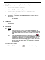
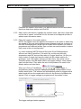
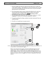
SOP:07:VL:018:03:NIBT
PAGE 1 of 7
Northern Ireland Blood Transfusion Service
STANDARD OPERATING
PROCEDURE
(Operational Copy)
Document Details
Document Number: SOP:07:VL:018:03:NIBT
No. of Appendices: NONE
Supersedes Number: 07:VL:018:02:NIBT
Document Title: QUICK GUIDE TO USING ELLAB PROBES
Prepared By: Eileen Taylor
Job Title: Validation Officer
Department: R A & C VALIDATION
Document Authorisation/ Issue & Implementation
Prepared By: E Taylor ______________________ Date: ____________________
Approved By: A Macauley _____________________
R A & C Manager
ISSUE DATE: 24 APRIL 2012
Date: ____________________
EFFECTIVE DATE: 30 APRIL 2012
CROSS REFERENCES
This SOP refers to the following documents:
Doc.
Type
Doc.
No.
SOP
VL:015
SOP
SOP
SOP
SOP
VL:016
VL:017
VL:022
VL:023
Title
Ellab ValSuite User Manual
Administration and Maintenance of Ellab Thermal Monitoring
Equipment
To run a session using Ellab TS Pro Probes
Result retrieval and analysis using Ellab Probe Data
External Calibration, Maintenance and Repair..
Preparing A Mapping Report
SOP:07:VL:018:03:NIBT
PAGE 2 of 7
Key Change from Previous Revision:
General update to version 2.8 and amended cross references
Screen dumps added
Responsibilities updated
1
2
RESPONSIBILITY
1.1
Validation Officer or deputy is responsible for ensuring Ellab equipment is
maintained in validated state and calibrated and updated on Q Pulse and in
Equipment Log
1.2
Validation Officer and Compliance Officer responsible for carrying out battery
and other ‘in house’ maintenance/calibration checks.
1.3
Validation and Compliance Officer responsible for the use of Ellab TS Pro
system to complete mappings and retrieving/compiling data for use in
temperature mapping reports.
INTRODUCTION
2.1
GENERAL
2.1.1
This SOP provides a quick guide to using the Ellab TS Pro system to
run a temperature mapping session. For more detail on how to
assemble and maintain the Ellab equipment as well as a
troubleshooting guide on what action to take with an error message,
refer to SOP:VL:015 ‘Administration and Maintenance of Ellab Thermal
Monitoring Equipment’.
Use of the Ellab system to run a temperature mapping session is
explained in detail in SOP:VL:016 ‘To Run a Session using Ellab TS
Pro Probes’.
Help with data analysis of results obtained is found in SOP:VL:017
‘Result Retrieval and Analysis using Ellab Probe Data’.
2.2
CLINICAL RELEVANCE/ PURPOSE OF EXAMINATION
Not Applicable.
2.3
PRINCIPLE OF EXAMINATION
Not Applicable.
3
HAZARD AND SAFETY PRECAUTIONS
SOP:07:VL:018:03:NIBT
4
PAGE 3 of 7
3.1
This procedure poses no significant health and safety risk.
MATERIALS
4.1
EQUIPMENT AND SPECIAL SUPPLIES
4.1.1
4.2
Ellab Thermal Monitoring Equipment
SPECIMEN REQUIREMENTS AND MEANS OF IDENTIFICATION
Not Applicable.
4.3
REAGENTS, STANDARDS OR CALIBRANTS AND INTERNAL CONTROL
MATERIALS
Not Applicable.
5
CALIBRATION
Not Applicable
6
PROCEDURE
6.1
Set-up
6.1.1
Check the clock time on the PC to ensure the logger settings are
correct and will start when expected. Connect any expansion modules
to the Master Reader Station then plug in PC cable. Place probes into
slots.
6.1.2
Open the Ellab software by clicking on the ValSuite Pro icon
on
your desktop or select it from your computer programmes. Enter your
User Name and Password in the ValSuite User Verification box on
screen. Confirm the icon for the reader station in the top right corner of
the Ellab screen has a green cable
and ready to use,
to denote it is plugged in
6.2 Starting TS Pro Loggers
6.2.1
Click the new session icon
, a new session window will appear
SOP:07:VL:018:03:NIBT
PAGE 4 of 7
Complete the session information, pre-defined names can be used where
there are drop down options and click OK.
6.2.2 Add a unit to the session; highlight the session name, right click, select add
unit the list of opens , select the unit for the area to be mapped and this is
added under the session name.
6.2.3 Place the loggers in the reader station.
NOTE: the loggers used are added to the session in the order in which they
are started. If you are using different types of sensors such as a mixture of
the dual RH/temperature, single rigid or flexible teflon sensors you need to
programme each different sensor type on their own and be aware of where
they come in the unit configuration
e.g. when mapping NIBTS General Stores the Dual RH/temperature
sensors are used in positions 3,3a and 4,4a, as they are dual with
temperature and RH sensors they take up 2 logger positions. So first you
have to place 2 single rigid sensor probes into the reader station for
positions 1 and 2 set logger settings and start them, then place 2 dual
Temp/RH probes into the reader station set logger settings, check sensor
type and start them. Then place the rest of the probes to be used in the
reader station and start them..
When you Click on TrackSense,
, Start Logger, a
programming window appears displaying a graphic representation of the
reader station slots. The software will automatically scan for loggers which
when found will turn the reader slot to blue for the first set of probes to be
started. Click on logger settings to programme all the probes in blue.
The logger settings window appears.
SOP:07:VL:018:03:NIBT
PAGE 5 of 7
1. Note the logger type at the top right side and make sure to select the
correct type of sensor. The programme notes the sensors you are using
so they will be available from the drop down menu but you must select
them yourself it is not automatic.
2. Set the start/stop times by check marking the Adjust box for start time
and for stop time and set the times required. Allow for the correct
equilibration time as in SOP:VL:016. Do not set times if to start
immediately and stop only when read.
3. Set the sample rate required; for 24hr mappings it’s 5mins, for 1 week
mappings it’s 15mins, for the Dometic freezers it’s 1minute.
4. To save the settings if setting a number of probes checkmark ‘Save as
default settings’
5. Click OK or if needed you can press cancel
1
2
3
4
5
6.2.4 When all selected slots turn green the loggers are programmed/started, it is
now possible to add additional loggers.
Remove the programmed loggers, place the additional loggers into the
reader station, click on refresh button, the reader station looks for the
added loggers, place a check mark in the ‘Select all logger devices’ at the
bottom of the box, click on the ‘Logger Settings’ button and programme as
before and repeat until all the loggers for this unit configuration have been
started.
SOP:07:VL:018:03:NIBT
PAGE 6 of 7
6.2.5 To check the ‘active’ (started) logger programming, click on ‘TrackSense’
and select ‘Logger List’. This will list all active loggers. Review the detail to
check loggers are programmed correctly.
6.2.6 Place the loggers in the area to be mapped according to the unit
configuration ensuring probes are in the correct positions.
6.3
Reading the TS Pro Loggers
6.3.1 Place the loggers into the Reader Station. As before go to TrackSense, but
select ‘Read Logger’. The Read Logger window appears; which looks the
same as the start window except that there is a ‘read’ button, the reader
automatically scans for loggers.
6.3.2 Checkmark ‘Select all Logger Devices’ (the first set of loggers placed into
the reader are selected automatically). Click ‘Read’. As each logger is read
the logger in the window turns green and the data from the loggers is
displayed behind the read logger window as a graph. Remove the read
loggers, place the additional loggers into the reader station, click the
‘refresh’ button, the reader scans for loggers, place a check mark in the
‘Select all logger devices’ at the bottom of the box. Click ‘Read’. When all
loggers have been read click ‘Close’ to remove the read logger window.
6.4
Graph Features, data analysis
6.4.1 For a detailed explanation on how to retrieve data refer to
SOP:VL:017:NIBT ‘Result Retrieval and Analysis of Ellab Probe Data’.
6.4.2 To view data from the graph, right click the mouse when it is placed on the
graph. This allows the option to Print Graph, Add Series Information, Add
Dataview, Add Internal Dataview, Copy Graph. Logger channels may be
selected and deselected using the Add Series Information feature.
6.5 Statistics
6.5.1 To get statistics, highlight the Session name, right click and select Add
Statistics. Add a name and description, then in the series box select the
sensor type from the drop down options, such as whether temperature or
humidity. Next select the loggers to be included in the statistics by check
marking each one to be included or click on ‘select all’. In the Time box
select the correct Start/Stop time stamps, usually ‘Time Marker 1 and stop
as Time Marker 2. At the right side of the box select the Functions, usually
min, max and average. Select the Output, usually Each Series and Global.
Click OK, uncheck graphic Representation unless you want a graph each
for global min, max and average. Click Ok, you see ‘Statistic’ on the
session tree after the Time Markers. If you edit your times, remove the
statistics and redo them.
6.6
Printing Reports
6.6.1 To print a report, select the print preview icon
from the top toolbar. A
window appears, check mark all the modules to be printed, to get a list of
SOP:07:VL:018:03:NIBT
PAGE 7 of 7
the raw data checkmark the ‘Data List’ and select the start and stop times
usually the time markers. If you have some channels from the data that you
have selected to make invisible checkmark the ‘Show Visible Data Only
option under ‘Data List’ to keep them out of the print. The other options can
be left at default and click ‘OK’ when done.
A preview of the report you have created opens in a Print Preview window
on screen. Select the printer icon to print the report and always export the
same report as ‘pdf’ to the Ellab folder on the ‘I’ drive ‘Ellab Exports’ for the
year and department to have a permanent pdf copy
6.6.2
6.7
Calibration
6.7.1
6.8
To export the data, click on Export icon
, an Export Report window
opens, which is a save window. Input the file name as the Mapping
Report Number and make sure to ‘save as type’ as ‘pdf’ and save as
mentioned into the Ellab Exports folder for that year and department in
the ‘I’ drive Ellab folder. Click on Save.
The loggers and all sensors are sent to Ellab DK for repair and annual
calibration and PPM as described in SOP:VL:022 External Calibration ,
Maintenance and Repair..
Maintenance
6.8.1
Probes must not be used outside the measuring range listed in the
technical specification and for which they are calibrated.
6.8.2
The loggers are to be stored with the batteries removed if not used on a
weekly basis.
6.8.3
The loggers and sensors are to be kept clean and stored in the boxes
assigned, in a cool dry area.
6.8.4
The loggers and sensors are sensitive electronic equipment and must be
treated with care.
6.8.5
Frequently lubricate the O-rings with silicone and when necessary
change the O-rings.
Further information may be obtained from the ValSuite 2.8 Edition User
Manual
6.9
LIMITATIONS OF THE EXAMINATION
Not Applicable.
7
RESULTS
7.1
Results obtained from temperature mappings are used to prepare mapping
reports as per SOP:VL:023 Preparing A Mapping Report.