1
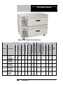
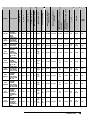
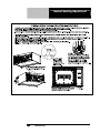
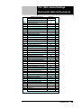
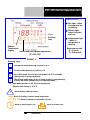
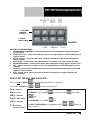
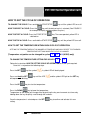
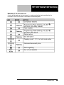
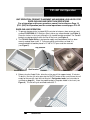
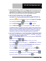
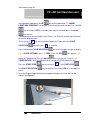
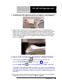
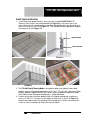
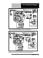
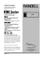
OPERATOR’S MANUAL
This manual provides information on
installation, operating, maintenance,
trouble shooting & replacement
parts for
Refrigerated Solutions with
FlexiCold Technology
FXFX-1
2N1 – TWO COOLING SYSTEMS IN ONE
Refrigerator (40°F)
• Freezer (-5°F)
• Or anywhere in between (-5° to 40°F)
FX1
FX1-4N1
4N1 – FOUR COOLING SYSTEMS IN ONE
• Refrigerator (40°F)
• Freezer (-5°F)
• Or anywhere in between (-5° to 40°F)
• Rapid Chiller for on-demand blast
chilling
• Safety Thaw for on-demand thawing of
frozen food safely
NOTIFY CARRIER OF DAMAGE AT ONCE.
It is the responsibility of the consignee to inspect
the container upon receipt of same and to
determine the possibility of any damage, including
concealed damage. Randell suggests that if you
are suspicious of damage to make a notation on
the delivery receipt. It will be the responsibility of
the consignee to file a claim with the carrier. We
recommend that you do so at once.
Manufacture Service/Questions 888-994-7636.
Information contained in this document is known to be
current and accurate at the time of printing/creation.
Unified Brands recommends referencing our product line
websites, unifiedbrands.net, for the most updated
product information and specifications.
12/12/2007
PP MNL0705-REV B
1055 Mendell Davis Drive
Jackson, MS 39272
888-994-7636 • Fax 888-864-7636
randellfx.com
2
888-994-7636
Table of Contents
page 2………………….….Table of Contents & Congratulations
page 3……..Serial Number Location & Parts & Service Hotline
page 4-8………………………………....Randell Limited Warranty
page 9-10..………………………………………Unit Specifications
page 11-12..…………………………………………Unit Installation
page 13………………………………..Gasket Sealing Adjustment
page 14...………………………..…….…FX-1(2N1) Unit Operation
page 15………………………………FX-1(2N1) Control Operation
page 16-17..…………………………...FX-1(2N1) Control Settings
page 18…………………….......FX-1(2N1)Control LED Functions
page 19……………….....FX-1(2N1) Control Setting Instructions
page 20-24……………………….…....FX1-4N1 Control Operation
page 25-27………………………….……FX1-4N1 Control Settings
page 28……………………….….FX1-4N1 Control LED Functions
page 29-34……………………….………..FX1-4N1 Unit Operation
page 29-32……FX1-4N1 Rapid Chill Operation
page 33-34…..FX1-4N1 Rapid Thaw Operation
page 35-36……………………….…..…..Preventive Maintenance
page 37……………………………...FX-1(2N1) Electrical Diagram
page 38…………………………....…..FX1-4N1 Electrical Diagram
page 39…………………………....…………..……Troubleshooting
page 40-42…………………........…FX-1(2N1) Replacement Parts
page 43-47………………………...…FX1-4N1 Replacement Parts
page 48-49………………………...…..…FX Series Optional Parts
Congratulations on your recent purchase of Randell food service equipment, and
welcome to the growing family of satisfied Randell customers.
Our reputation for superior products is the result of consistent quality craftsmanship. From the
earliest stages of product design to successive steps in fabrication and assembly, rigid standards
of excellence are maintained by out staff of designers, engineers, and skilled employees.
Only the finest heavy-duty materials and parts are used in the production of Randell brand
equipment. This means that each unit, given proper maintenance will provide years of trouble free
service to its owner.
randellfx.com
3
In addition, all Randell food service equipment is backed by
some of the best warranties in the food service industry and by
our professional staff of service technicians.
Retain this manual for future reference.
NOTICE: Due to a continuous program of product improvement, Randell
reserves the right to make changes in design and specifications without prior
notice.
NOTICE: Please read the entire manual carefully before installation. If certain
recommended procedures are not followed, warranty claims will be denied.
MODEL NUMBER _________________________
SERIAL NUMBER _________________________
INSTALLATION DATE _____________________
The serial number is located in the cabinet left side wall. Removal of the
insulated insert from the drawer will be nessecary to view data plate.
800-621-8560
4
888-994-7636
Randell Service and Parts
Hotline
Warranty Policies
Congratulations on your purchase of a Randell Manufactured piece of equipment.
Randell believes strongly in the products it builds and backs them with the best
warranty in the industry. Standard with every unit is the peace of mind that this unit
has been thoroughly engineered, properly tested and manufactured to excruciating
tolerances, by a manufacturer with over 30 years of industry presence. On top of
that front end commitment, Randell has a dedicated staff of certified technicians
that monitor our own technical service hotline at 1-800-621-8560 to assist you with
any questions or concerns that may arise after delivery of your new Randell
equipment.
PARTS WARRANTY
1. One year parts replacement of any and all parts that are found defective in
material or workmanship. Randell warrants all component parts of
manufactured new equipment to be free of defects in material or workmanship,
and that the equipment meets or exceeds reasonable industry standards of
performance for a period of one year from the date of shipment from any
Randell factory, assembly plant or warehouse facility.
NOTE: warranties are effective from date of shipment, with a thirty day
window to allow for shipment, installation and set-up. In the event
equipment was shipped to a site other than the final installation site,
Randell will warranty for a period of three months following installation,
with proof of starting date, up to a maximum of fifteen months from the
date of purchase.
2. Free ground freight of customer specified location for all in warranty parts
within continental U.S. Component part warranty does not cover glass
breakage or gasket replacement. Randell covers all shipping cost related to
component part warranty sent at regular ground rates (UPS, USPS). Freight
or postage incurred for any express or specialty methods of shipping are
the responsibility of the customer.
LABOR COVERAGE
In the unlikely event a Randell manufactured unit fails due to defects in
materials or workmanship within the first ninety days, Randell agrees to pay
the contracted labor rate performed by an Authorized Service Agent (ASA).
Any work performed by a non-ASA will not be honored by Randell. Please
consult Randell Technical Support (800-621-8560) for a complete listing of
ASAs or visit the service page of our website: www.unifiedbrands.net.
Warranties are effective from date of shipment, with a thirty day window to
allow for shipment, installation and setup. Where equipment is shipped to any
site other than final installation, Randell will honor the labor warranty for a
period of ninety days following installation with proof of starting date, up to a
maximum of six months from date of purchase.
randellfx.com
5
Warranty Policies con’t
Temperature adjustments are not covered under warranty, due to the wide
range of ambient conditions.
WHEN OPTIONAL 5 YEAR COMPRESSOR WARRANTY APPLIES
1. Provide reimbursement to an ASA for the cost of locally obtained
replacement compressor in exchange for the return of the defective
compressor sent back freight prepaid. Note: Randell does limit
amount of reimbursement allowed and does require bill from local
supply house where compressor was obtained (customer should not
pay servicing agent up front for compressor).
2. Provide repair at the manufacturing facility by requiring that the
defective unit be sent back to Randell freight prepaid. Perform repair at
the expense of Randell and ship the item back to the customer freight
collect.
3. Furnish complete condensing unit freight collect in exchange for the
return of the defective compressor sent back freight prepaid.
(Decisions on whether or not to send complete condensing units will be
made by Randell’s in-house service technician).
WHEN OPTIONAL LABOR EXTENSION POLICY APPLIES
Randell will provide reimbursement of labor to an ASA for any customer that
has an optional labor extension of our standard warranty. (Contracted rates do
apply) Randell offers both 1 and 2 year extensions. Labor extensions begin at
the end of our standard warranty and extend out 9 months to 1 calendar year
or 21 months to 2 calendar years from date of purchase. Please contact
Randell Manufacturing’s technical service hotline at 1-800-621-8560 for details
and any question on Authorized Service Agents (ASA).
WHEN EXPORT WARRANTIES APPLY
1. Randell Manufacturing covers all non-electrical components under the
same guidelines as our standard domestic policy.
2. All electrical components operated on 60 cycle power are covered
under our standard domestic policy.
3. All electrical components operated on 50 cycle power are covered for
90 days from shipment only.
4. Extended warranty options are not available from the factory.
6
888-994-7636
Warranty Policies con’t
ITEMS NOT COVERED UNDER WARRANTY
1. Maintenance type of repairs such as condenser cleaning, temperature
adjustments, clogged drains and unit leveling.
2. Randell does not cover gaskets under warranty. Gaskets are a
maintenance type component that are subject to daily wear and tear
and are the responsibility of the owner of the equipment. Because of
the unlimited number of customer related circumstances that can cause
gasket failure all gasket replacement issues are considered nonwarranty. Randell recommends thorough cleaning of gaskets on a
weekly basis with a mild dish soap and warm water. With proper care
Randell gaskets can last up to two years, at which time we recommend
replacement of all gaskets on the equipment for the best possible
performance.
NOTICE: FOOD LOSS IS NOT COVERED UNDER WARRANTY
3. Repairs caused by abuse such as broken glass, freight damage, or
scratches and dents.
4. Electrical component failure due to water damage from cleaning
procedures.
QUOTATIONS
Verbal quotations are provided for customer convenience only and are
considered invalid in the absence of a written quotation. Written quotations
from Randell are valid for 30 days from quote date unless otherwise specified.
Randell assumes no liability for dealer quotations to end-users.
SPECIFICATION & PRODUCT DESIGN
Due to continued product improvement, specification and product design may
change without notice. Such revisions do not entitle the buyer to additions.
Changes or replacements for previously purchased equipment.
SANITATION REQUIREMENTS
Certain areas require specific annotation requirements other than N.S.F. &
U.L. standards. Randell must be advised of these specifications before
fabrication of equipment. In these special circumstances, a revised quotation
may be required to cover additional costs. Failure to notify Randell before
fabrication holds the dealer accountable for all additional charges.
CANCELLATIONS
Orders
canceled
prior
to
production scheduling
entered into
engineering/production and cancelled are subject to a cancellation charge
(contact factory for details).
randellfx.com
7
Warranty Policies con’t
STORAGE CHARGES
Randell makes every effort to consistently meet our customer’s shipment
expectations. If after the equipment has been fabricated, the customer
requests delay in shipment, and warehousing is required:
1. Equipment held for shipment at purchasers request for a period of 30
days beyond original delivery date specified will be invoiced and
become immediately payable.
2. Equipment held beyond 30 days after the original delivery date
specified will also include storage charges.
SHIPPING & DELIVERY
Randell will attempt to comply with any shipping, routing or carrier request
designated by dealer, but reserves the right to ship merchandise via any
responsible carrier at the time equipment is ready for shipment. Randell will
not be held responsible for any carrier rate differences; rate differences are
entirely between the carrier and purchaser. Point of shipping shall be
determined by Randell (Weidman, MI/Tucson, AZ/Jackson, MS). At dealer’s
request, Randell will endeavor whenever practical to meet dealer’s request.
Freight charges to be collect unless otherwise noted.
DAMAGES
All crating conforms to general motor carrier specifications. To avoid
concealed damage, we recommend inspection of every carton upon receipt.
In the event the item shows rough handling or visible damage to minimize
liability, a full inspection is necessary upon arrival. Appearance of damage will
require removing the crate in the presence of the driver. A notation must be
placed on the freight bill and signed for by the truck driver at the time of
delivery.
Any and all freight damage that occurs to a Randell piece of
equipment as a result of carrier handling is not considered under warranty, and
is not covered under warranty guidelines. Any freight damage incurred during
shipping needs to have a freight claim filed by the receiver with the shipping
carrier. Consignee is responsible for filing of freight claims when a clear
delivery receipt is signed. Claims for damages must be filed immediately
(within 10 days) by the consignee with the freight carrier and all cartons and
merchandise must be retained for inspection.
8
888-994-7636
Warranty Policies con’t
RETURNED GOODS
Authorization for return must first be obtained from Randell before returning
any merchandise.
Any returned goods shipment lacking the return
authorization number will be refused, all additional freight costs to be borne by
the returning party. Returned equipment must be shipped in original carton,
freight prepaid and received in good conditions. Any returned merchandise is
subject to a minimum handling charge (consult factory for rate).
INSTALLATION
Equipment installation is the responsibility of the dealer and/or their customer.
Randell requires all equipment to be professionally installed.
PENALTY CLAUSES
Dealer penalty clauses, on their purchase order or contractually agreed to
between the dealer and their clients are not binding on Randell. Randell does
not accept orders subject to penalty clauses. This agreement supersedes any
such clauses in dealer purchase orders.
*FOOTNOTES IN REFERENCE TO PARAGRAPHS ABOVE
1. Herein called Randell.
2. NET means list price less discount, warranty, labor policy, freight, Randell delivery and other
miscellaneous charges.
CASH DISCOUNTS WILL BE CALCULATED ON NET ONLY.
randellfx.com
9
Unit Specifications
FX-2WS
FX-3SS
46”
29.6”
16.4"
1
3.0
6.1cc
3.9
1.22kw
48"
33"
24"
1
3.0
6.1cc
3.9
96"
33"
24"
2
6.0
6.1cc
each
46”
29.6"
37.3"
2
6.0
46”
29.6"
53.7"
3
9.0
10
888-994-7636
POWER USAGE (PER DAY)
(FREEZER)
FX-2CS
D
R
A
W
E
R
S
POWER USAGE (PER DAY)
(REFRIGERATOR)
FX-1CS
FLEXICOLD 1
SECTION
SYSTEM 2N1
BASE MODEL
FLEXICOLD 1
SECTION 2N1
EQUIPMENTTOP SYSTEM
FLEXICOLD 2
SECTION 2N1
EQUIPMENTTOP SYSTEM
FLEXICOLD 2
SECTION 2N1
PREP WORKTOP SYSTEM
FLEXICOLD 3
SECTION 2N1
PRECISION
STORAGE
SYSTEM
H
E
I
G
H
T
ACTUAL AMP DRAW
FX-1
Description
D
E
P
T
H
COMPRESSOR SIZE
Model
L
E
N
G
T
H
CUBIC FEET OF STORAGE
Model FX-2WS Double Flexi-Cold Drawer
V
O
L
T
S
N
E
M
A
SHIP
WT.
lbs
1.99kw
115
5-15p
245
1.22kw
1.99kw
115
5-15p
385
7.8
2.44kw
3.98kw
115
5-15p
770
6.1cc
each
7.8
2.44kw
3.98kw
115
5-15p
635
6.1cc
each
11.7
3.66kw
5.97kw
115
5-15p
891
FX24N1WST
FX24N1WSB
FX34N1SST
FX34N1SSTC
POWER USAGE
(PER 6 HOUR RAPID THAW CYCLE
EACH UNIT)
FX24N1WS
POWER USAGE
(PER 4 HOUR BLAST CHILLER CYCLE
EACH UNIT)
FX24N1CSR
115
5-15p
250
2.1 kw
1.4 kw
115
5-15p
390
3.98 kw
2.1 kw
1.4 kw
115
ea.
(2)
5-15p
780
2.44 kw
3.98 kw
2.1 kw
1.4 kw
115
5-15p
780
10.2
2.44 kw
3.98 kw
2.1
kw
1.4 kw
115
5-15p
780
6.3
ea.
2.44 kw
3.98 kw
2.1
kw
1.4 kw
115
ea.
(2)
5-15p
645
10.2
2.44 kw
3.98 kw
2.1
kw
1.4 kw
115
5-15p
645
10.2
2.44 kw
3.98 kw
2.1
kw
1.4 kw
115
5-15p
645
3.66 kw
5.97 kw
2.1
kw
1.4 kw
115
ea.
(2)
5-15p
905
3.66 kw
5.97 kw
2.1
kw
1.4 kw
115
ea.
(2)
5-15p
905
POWER USAGE (PER DAY)
(FREEZER)
FX24N1CSL
1.4 kw
POWER USAGE (PER DAY)
(REFRIGERATOR)
FX24N1CS
2.1 kw
S
E
C
T
I
O
N
S
ACTUAL AMP DRAW
FX14N1CS
FLEXICOLD 1
SECTION
SYSTEM 4N1
BASE
MODEL
FLEXICOLD 1
SECTION 4N1
EQUIPMENTTOP SYSTEM
FLEXICOLD 2
SECTION 4N1
EQUIPMENTTOP SYSTEM
FLEXICOLD 2
SECTION
COMBO
EQUIPMENTTOP SYSTEM
4N1 LF 2N1
RT
FLEXICOLD 2
SECTION
COMBO
EQUIPMENTTOP SYSTEM
2N1 LF 4N1
RT
FLEXICOLD 2
SECTION 4N1
PREP WORKTOP SYSTEM
FLEXICOLD 2
SECTION
COMBO
PREP WORKTOP SYSTEM
4N1 TOP
FLEXICOLD 2
SECTION
COMBO
PREP WORKTOP SYSTEM
4N1 BOTTOM
FLEXICOLD 3
SECTION
COMBO
PRECISION
STORAGE
SYSTEM 4N1
TOP
FLEXICOLD 3
SECTION
COMBO
PRECISION
STORAGE
SYSTEM 4N1
TOP 2
SHIP
WT.lbs
H
E
I
G
H
T
COMPRESSOR SIZE
FX1-4N1
Description
N
E
M
A
D
E
P
T
H
CUBIC FEET OF STORAGE
Model
V
O
L
T
S
L
E
N
G
T
H
46”
29.6”
16.4"
1
3.0
8.8cc
6.3
1.22 kw
1.99 kw
48"
33"
24"
1
3.0
8.8cc
6.3
1.22 kw
1.99 kw
96"
33"
24"
2
6.0
8.8cc
each
6.3
ea.
2.44 kw
10.2
96"
33"
24"
2
6.0
96"
33"
24"
2
6.0
46”
29.6"
37.3"
2
6.0
46”
46”
46”
46”
29.6"
29.6"
29.6"
29.6"
37.3"
37.3"
53.7"
53.7"
2
2
3
3
6.0
6.0
9.0
9.0
(1)
8.8cc
(1)
6.1cc
(1)
6.1cc
(1)
8.8cc
8.8cc
each
(1)
8.8cc
(1)
6.1cc
(1)
6.1cc
(1)
8.8cc
(1)
8.8cc
(2)
6.1cc
(2)
8.8cc
(1)
6.1cc
6.3
&
7.8
6.3
&
10.2
randellfx.com
11
Unit Installation
SELECTING A LOCATION FOR YOUR NEW UNIT
The following conditions should be considered when selecting a location for your
unit:
1. Floor Load: The area on which the unit will rest must be level, free of
vibration, and suitably strong enough to support the combined weights
of the unit plus the maximum product load weight
2. Clearance: Clearance for opening the drawer and access to its
contents is the only requirements. Do not place any object that can
block the ventilation exhaust from the machine compartment register.
3. Ventilation: The air cooled self contained unit requires a sufficient
amount of cool clean air. Avoid surrounding your equipment stand
around other heat generating equipment and out of direct sunlight.
Also, avoid locating in an unheated room or where the room
temperature may drop below 55° F or above 90° F.
INSTALLATION CHECKLIST
After the final location has been determined, refer to the following checklist prior to
start-up:
1. Check all exposed refrigeration lines to ensure that they are not kinked,
dented, or rubbing together.
2. Check that the condenser and evaporator fans rotate freely without
striking any stationary members.
3. Unit must be properly leveled; check all legs or casters to ensure they
all are in contact with the floor while maintaining a level work surface.
Adjusting bullet feet heights or shimming casters may be necessary if
the floor is not level. NOTE: Damage to equipment may result if not
followed. Randell is not responsible for damage to equipment if
improperly installed.
4. Plug in unit and turn on main on/off power switch. The main power
switch is located in the front panel next to the digital control
5. Allow unit time to cool down to temperature. If temperature adjustments
are required, the temperature control is located on the front panel.
Confirm that the unit is holding the desired temperature.
6. Refer to the front of this manual for serial number location. Please
record this information in your manual on page 3 now. It will be
necessary when ordering replacement parts or requesting warranty
service.
7. Before putting in food, allow your unit to operate for approximately (1)
hour so that interior of the unit is cooled down to storage temperature.
NOTE: All motors are oiled and sealed.
NOTE: FAILURE TO FOLLOW INSTALLATION GUIDELINES AND
RECOMMENDATIONS MAY VOID THE WARRANTY ON YOUR UNIT.
12
888-994-7636
Unit Installation con’t
ELECTRICAL SUPPLY: Any wiring should be done by a qualified electrician in
accordance with local electrical codes. A properly wired and grounded outlet will
assure proper operation. Please consult the data tag attached to the compressor
to ascertain the correct electrical requirements. Supply voltage and amperage
requirements are located on the serial number tag located inside the mechanical
housing.
NOTE: It is important that a voltage reading be made at the compressor
motor electrical connections, while the unit is in operation to verify the
correct voltage required by the compressor is being supplied. Low or high
voltage can detrimentally affect operation and thereby void its warranty.
NOTE: it is important that your unit has its own dedicated line. Condensing
units are designed to operate with a voltage fluctuation of plus or minus 10%
of the voltage indicated on the unit data tag. Burn out of a condensing unit
due to exceeding voltage limits will void the warranty.
randellfx.com
13
Gasket Sealing Adjustment
14
888-994-7636
FX-1 (2N1) Unit Operation
PRODUCT PLACEMENT AND MAXIMUM LOAD LEVELS
1. This unit’s insulated drawer insert is provided and designed to
hold food products with or without containers.
2. Refrigerated or freezer tempered air is introduced into the
insulated drawer insert from above and circulates around the
product for even temperature distribution.
3. For the unit to operate at full efficiency the drawer seals
should be maintained in good condition. It is essential that
product is not stored above the Max Fill line as this can
damage the seals and affect the operation of the unit.
4. This unit is designed for holding products at temperatures -5°F
to 40°F. Products placed in unit should be pre-chilled to the
holding temperature. This unit is not intended for use as a pull
down cabinet.
5. The unit is capable of storing any food product. However,
products which may give off acidic odors like vinegar, onions,
etc should be suitably sealed. Randell also recommends
containers with liquid food products be stored with lids.
6. The drawer system is designed for easy unobstructed access to
the product in the insulated drawer insert. The track should run
smoothly with little resistance during the motion of opening and
closing the drawer. The drawer will have more resistance when
the unit is warm and not operating in either the refrigeration or
freezer mode, this is normal as the gasket will contract slightly
when the unit is cooling and allow smooth travel of the drawer.
randellfx.com
15
FX-1 (2N1) Control Operation
AMBIENT CONDITIONS
1. This unit is designed for operation in a room ambient of 86°F / 55% relative humidity. It should
never be used outside or located in direct sunlight.
Randell has attempted to preset the temperature control to ensure that your unit runs at an optimum
temperature, but due to varying ambient conditions, including elevation, food type and your type of
operation, you may need to alter this temperature.
Your FX-1 (2N1) Series Unit is equipped with an
electronic temperature control. Figure 1, left, illustrates
the Dixell XR60C control location on the front above the
louvered panel.
Figure 1
Figure 2, left, illustrates an alternate electronic
temperature control, Dixell XR60CX with blue LED.
Before making temperature adjustments:
A. Allow adequate time for the cabinet temperature to equalize. When initially started or when
first loaded, it can take a long time for temperatures in the display area to stabilize.
B. Make sure that unit operation is not being effected by room ambient conditions. (See Ambient
Conditions section above). If there are any significant ambient issues, adjusting the temperature
setting may not help.
To raise temperature:
A. Push and hold the “SET” button until set point 33 appears then release the “SET” button.
33 is the current set point temperature.
B. Push and release the up arrow 1 or more times until the desired temperature is displayed.
Push and release the “SET” button one time. The new set point will flash 3 times and then
will be locked in.
To lower temperature:
A. Push and hold the “SET” button until 33 appears and then release the “SET” button. 33 is
the current set point temperature.
B. Push and release the up arrow 1 or more times until the desired temperature is displayed.
Push and release the “SET” button one time. The new set point will flash 3 times and then
will be locked in.
NOTE: The FX-1 (2N1) Series Unit is designed to operate in both refrigerated or freezer
mode by adjusting the “SET” point to the desired temperature. The maximum highest
setting is 40°F and the minimum lowest setting is -5°F. If the settings need to go above or
below this point there may be other contributing factors as to the cause of the
temperature variances, please contact the factory at 1-800-621-8560.
16
888-994-7636
FX-1 (2N1) Control Settings
Dixell control XR60C-4N1F0 w/Red LED
Code
SET
HY
LS
US
Ot
P2P
OE
OdS
AC
CCt
COn
COF
CF
Lod
rES
tdF
dtE
IdF
ndF
dSd
dFd
dAd
Fdt
dPo
dAF
FnC
Fnd
Fct
FSt
ALc
ALU
ALL
ALd
dAO
ilP
ilF
did
nPS
odC
PbC
dP1
dP2
rEL
Ptb
Randell Control Settings
XR60C-4N1F0
Randel Part No.
Locked
Thermostat set point
Thermostat Differential (hysterisis)
Lower Set Point
Upper Set Point
Offset Room Temp
2nd Probe Present
Evaporator Probe Calibration
Output delay @ Startup
Anti-Cycle Time (min off after cycle)
Comp Continuous time, (Fast Freeze)
Compressor ON time (probe failure)
Compressor OFF (probe failure)
°C /°F
Probe Displayed (P1 or P2)
Resolution 0.0°C (only °C)
Defrost Type
Defrost Termination Temp
Interval between Defrosts
(Maximum) length of Defrost
Start defrost delay
Display during Defrost
Max display delay after defrost
Drip time after defrost end
First defrost after startup
Defrost delay after Fast Freezing
Fan Operating Mode
Fan Delay after Defrost
Fan Temperature Differential
Fan Stop Temperature (coil temp)
Alarm Configuration
Alarm Upper (max alarm)
Alarm Lower (minimum alarm)
Alarm Delay (min)
Alarm Delay at startup (hrs/.10min)
Digital Input Polarity (Door Switch)
Digital Input Configuration
Digital Input Delay (Door Open)
Switch Action
Compressor and Fan Status
Probe Selection PTC/NTC
Display Probe 1 (Room Probe)
Display Probe 2 (Coil Probe)
Software Info
Software info
bold = hidden Parameters
FX-Series
Freezer
RF CNT0604
NO
-1
2
-4
59
0
Y
0
0
1
3
5
5
F
P1
IN
EL
45
12
30
0
dEF
12
3
Y
0
o-n
4
0
65
Ab
65
-10
90
1.3
OP
dor
10
0
F_C
ntc
-
Code
SET
HY
LS
US
Ot
P2P
OE
OdS
AC
CCt
COn
COF
CF
Lod
rES
tdF
dtE
IdF
ndF
dSd
dFd
dAd
Fdt
dPo
dAF
FnC
Fnd
Fct
FSt
ALc
ALU
ALL
ALd
dAO
ilP
ilF
did
nPS
odC
PbC
dP1
dP2
rEL
Ptb
randellfx.com
17
FX-1 (2N1) Control Settings
Dixell control XR60CX-4N1F0 w/Blue LED
Randell Control Settings
DIXELL PART NUMBER XR60CX-4R0F1
FX-Series
2N1
SETTINGS
Randell Control Settings
DIXELL PART NUMBER XR60CX-4R0F1
RANDELL PART NUMBER RF CNT0707
CODE
Prb
LOCKED
READ PROBE
rPr
ROOM TEMPERATURE PROBE READING
Set
SET POINT
FX-Series
2N1
SETTINGS
RANDELL PART NUMBER RF CNT0707
NO.
CODE
CODE
-
Prb
dAF
DEFROST DELAY AFTER FAST FREEZING
LOCKED
READ
ONLY
rPr
Fnc
FANS OPERATING MODE
-1
Set
Fnd
FAN DELAY AFTER DEFROST
0
Fct
65
FSt
PR1
USER VARIABLE PARAMETERS
-
PR1
Fct
DIFFERENTIAL OF TEMP. FOR FORCED
ACTIVATION OF FANS
Set
SET POINT
-1
Set
FSt
FAN STOP TEMPERATURE
NO.
CODE
0
dAF
O-N
Fnc
4
Fnd
HY
DIFFERENTIAL
2
HY
Fon
FAN ON TIME WITH COMPRESSOR OFF
0
Fon
LS
MINIMUM SET POINT
-5
LS
FoF
FAN OFF TIME WITH COMPRESSOR OFF
0
FoF
US
MAXIMUM SET POINT
59
US
FAP
PROBE SELECTION FOR FAN MANAGEMENT
P2
FAP
THERMOSTAT PROBE CALIBRATION
0
Ot
ALc
TEMPERATURE ALARMS CONFIGURATION
AB
ALc
P2P
EVAPORATOR PROBE PRESENCE
Y
P2P
ALU
MAXIMUM TEMPERATURE ALARM
65
ALU
OE
EVAPORATOR PROBE CALIBRATION
0
OE
ALL
MINIMUM TEMPERATURE ALARM
-10
ALL
AFH
DIFFERENTIAL FOR TEMPERATURE ALARM
RECOVERY
1
AFH
TEMPERATURE ALARM DELAY
Ot
P3P
THIRD PROBE PRESENCE
N
P3P
O3
THIRD PROBE CALIBRATION
0
O3
ALd
P4P
FOURTH PROBE PRESENCE
N
P4P
dAO
DELAY OF TEMPERATURE ALARM AT START
UP
PROBE FOR TEMPERATURE ALARM OF
CONDENSER
90
ALd
1.3
dAO
O4
FOURTH PROBE CALIBRATION
0
O4
AP2
NP
AP2
OdS
OUTPUT DELAY AT START UP
0
OdS
AL2
CONDENSER FOR LOW TEMPERATURE ALARM
-40
AL2
AC
ANTI-SHORT CYCLE DELAY
rtr
P1-P2 PERCENTAGE OF REGULATION
CCt
CCS
COn
COF
CONTINUOUS CYCLE DURATION
SET POINT FOR CONTINUOUS CYCLE
COMPRESSOR ON TIME WITH FAULTY
PROBE
COMPRESSOR OFF TIME WITH FAULTY
PROBE
1
AC
AU2
CONDENSER FOR HIGH TEMPERATURE ALARM
230
AU2
100
rtr
AH2
DIFFERENTIAL FOR CONDENSER
TEMPERATURE ALARM RECOVERY
4
AH2
3
CCt
AD2
CONDENSER TEMPERATURE ALARM DELAY
15
AD2
1.3
dA2
N
bLL
N
AC2
0
CCS
dA2
5
COn
bLL
5
COF
AC2
DELAY FOR CONDENSER TEMPERATURE
ALARM AT START UP
COMPRESSOR OFF FOR CONDENSER LOW
TEMPERATURE ALARM
COMPRESSOR OFF FOR CONDENSER HIGH
TEMPERATURE ALARM
CF
TEMPERATURE MEASUREMENT UNITS
F
CF
i1P
DIGITAL INPUT POLARITY
OP
i1P
rES
RESOLUTION
IN
rES
i1F
DIGITAL INPUT CONFIGURATION
dor
i1F
Lod
PROBE DISPLAYED
P1
Lod
did
DIGITAL INPUT ALARM DELAY
10
did
0
Nps
F_C
odc
Y
rrd
0
HES
NTC
PbC
1
Adr
NUMBER OF ACTIVATIONS OF PRESSURE
SWITCH
COMPRESSOR AND FAN STATUS WITH DOOR
OPEN
REGULATION RESTART WITH DOOR OPEN
ALARM
rEd
X-REP DISPLAY
P
rEd
Nps
dLy
DISPLAY TEMPERATURE DELAY
0
dLy
odc
dtr
p1-p2 PERCENTAGE FOR DISPLAY
50
dtr
rrd
tdF
DEFROST TYPE
EL
tdF
HES
DIFFERENTIAL FOR ENERGY SAVING
dFP
PROBE SELECTION FOR DEFROST
TERMINATION
P2
dFP
PbC
KIND OF PROBE
dtE
DEFROST TERMINATION TEMPERATURE
45
dtE
Adr
SERIAL ADDRESS
IdF
INTERVAL BETWEEN DEFROST CYCLES
8
IdF
onF
ON/OFF KEY ENABLING
NU
onF
NdF
MAXIMUM LENGTH FOR DEFROST
35
NdF
dP1
ROOM PROBE DISPLAY
-
dP1
dSd
START DEFROST DELAY
dFd
DISPLAYING DURING DEFROST
0
dSd
dP2
EVAPORATOR PROBE DISPLAY
-
dP2
DEF
dFd
dP3
THIRD PROBE DISPLAY
-
dP3
dAd
MAXIMUM DISPLAY DELAY AFTER
DEFROST
12
dAd
dP4
FOURTH PROBE DISPLAY
-
dP4
Fdt
DRAINING TIME
3
Fdt
rSe
REAL SET POINT
-
rSe
dPo
FIRST DEFROST AFTER STARTUP
Y
dPo
rEL
SOFTWARE RELEASE
-
rEL
Ptb
MAP CODE
-
Ptb
bold = hidden Parameters
18
888-994-7636
FX-1 (2N1) Control LED Functions
USE OF LEDS
Each LED function is described in the following table.
randellfx.com
19
FX-1 (2N1) Control Settings
DIXELL CONTROL SETTING INSTRUCTIONS
HOW TO CHANGE A PARAMETER VALUE
To change the parameter’s values operate as follows:
1. Enter the Programming mode by pressing the Set and Down Arrow for 3
seconds (the defrost and water drops symbol will start blinking)
2. Select the required parameter.
3. Press the “SET” key to display its value. (Now only the defrost symbol is
blinking).
4. Use up or down arrow to change its value.
5. Press “SET” to store the new value and move to the following parameter.
To Exit: Press SET + up arrow or wait 15 seconds without pressing a key.
THE HIDDEN MENU
The hidden menu includes all the parameter of the instrument.
HOW TO ENTER THE HIDDEN MENU
1. Enter the Programming mode by pressing the set + down arrow key for 3
seconds (the defrost and water drops symbol will start blinking)
2. When a parameter is displayed; keep pressed the Set + down arrows for
3.
4.
5.
6.
more than 7 seconds. The Pr2 label will be displayed immediately followed
from the HY parameter.
NOW YOU ARE IN THE HIDDEN MENU.
Select the required parameter.
Press the “SET” key to display its value (Now only the defrost symbol LED
is blinking).
Use up or down arrow to change its value.
Press “SET” to store the new value and move to the following parameter.
HOW TO LOCK THE KEYBOARD
1. Keep pressed for more than 3 seconds the up and down arrow keys.
2. The “POF” message will be displayed and the keyboard will be locked.
At this point it will be possible only to see the set point or the MAX or Min
temperature stored.
3. If a key is pressed more than 3 seconds the “POF” message will be
displayed.
TO UNLOCK THE KEYBOARD
1. Keep pressed together for more than 3 seconds the up and down arrow
keys till the “POn” message will be displayed.
20
888-994-7636
FX1- 4N1 Control Operation
ELECTRONIC CONTROL FEATURES AND OPERATIONS
Randell has attempted to preset the temperature control to ensure that your unit operates at an optimum
temperature, but due to varying ambient conditions, including elevation, food type and your type of
operation, you may need to alter this temperature.
FIGURE-A
Your FX1-4N1 Series Unit is equipped with an electronic temperature control. Figure A, above,
illustrates the control location on the front above the louvered panel. This control is a Dixell model
number XB570L with a blue LED display and stainless steel cover.
FIGURE-B
Figure B shows the control without the stainless steel cover and with the examples of the displayed
information available with this control. The Randell FX1-4N1 control will feature a blue LED display
in place of the red display shown in Figure B.
randellfx.com
21
FX1- 4N1 Control Operation con’t
DISPLAY KEY:
Fan light – when
lit evaporator fan
is running
Defrost light –
when lit defrost
cycle on
Auxiliary
relay
Cabinet
Temperature
display
Timer/Clock/Insert probe temperature
(IP1, IP2, IP3)
FIGURE - C
Running cycle
1
Refrigerator mode operating set point at 35°F
2
Freezer mode operating set point at -4°F
3
Quick Chill mode chills 22 lbs of hot product to 35°F and holds
automatically in refrigerated mode
4
Rapid Thaw mode thaws 20 lbs of frozen product in approximately
6 hours and holds automatically in refrigerated mode
H
!
Hold Mode operates at any set point temperature.
Set point from factory is at 35°F
Alarm display indicates failure
aux2 When lit Auxiliary function mode in operation
IP1, IP2, IP3 When lit indicates insert probe is in use
When lit Timer mode is set
22
888-994-7636
When lit Printer is on
Compressor light
– when lit
compressor is
running
Measurement unit
°C = Celsius
°F = Fahrenheit
FX1- 4N1 Control Operation con’t
1 – UP/TEMP/
MANUAL
DEFROST
5 – DOWN/
TEMP/ CLOCK
FIGURE-D
CONTROL KEY DESCRIPTIONS
1. UP/TEMP/MANUAL DEFROST – used to browse menu, raise temperature settings and activate
manual defrost.
2. START/STOP cycle – used to start and stop current cycle monitored by the yellow LED upper left
corner of button.
3. CYCLE selection – used to browse cycles 1 through 4 monitored by the yellow LED upper left
corner of button.
4. LIGHT button – used to switch the light on and off (this button is not used in model FX1-4N1).
5. DOWN/TEMP/CLOCK – used to browse menu, lower temperature settings and set real time clock
6. SET – used to change the set points in any cycle monitored by the yellow LED upper left corner
of button.
7. PRINTER – used to enable/disable the printer if printer is provided monitored by the yellow LED
upper left corner of button.
8. AUX – used to switch auxiliary functions on and off monitored by the yellow LED upper left
corner of button.
HOW TO SET THE REAL TIME CLOCK (RTC)
Press and hold the DOWN
key until the nIn label (minutes) is displayed.
Use the UP and DOWN key
or
to browse the parameters.
n I n = minutes
H o u = hours
d A y = date day
n o n = date month
y E A = date year
t I n = USA or
Europe (EU) time
TO MODIFY: Press the SET
key and then the UP
and DOWN
keys.
TO CONFIRM: Press the SET
key.
TO EXIT THE RTC MENU: Press together the SET
wait 5 seconds.
+
UP keys or
randellfx.com
23
FX1- 4N1 Control Operation con’t
HOW TO SET THE CYCLE OF OPERATION
TO CHANGE THE CYCLE: Press and hold the START/STOP
key until the yellow LED turns off.
HOW TO SELECT A CYCLE: Press the
key until the desired cycle is selected. (See FIGURE-C
for example of display and description of cycles.)
HOW TO START A CYCLE: Press the START/STOP
switched on.
key. The correspondent yellow LED is
HOW TO STOP A CYCLE: Press and hold the START/STOP
key until the yellow LED turns off.
HOW TO SET THE TEMPERATURE WITHIN EACH CYCLE OF OPERATION
SETTING THE TEMPERATURES IN THIS MANNER IS TEMPERARY AND WILL REVERT TO STANDARD
TEMPERATURE SETTINGS WHEN THE CYCLE IS CHANGED
(Temperature set points can be changed in cycles
1
TO CHANGE THE TEMPERATURE SETTING FOR CYCLES
2
& H (HOLD) only)
1
&
2
:
Follow the instructions HOW TO SET THE CYCLE OF OPERATION to set the cycle required.
Once this is set perform the following steps.
Press the SET
key the symbol
Press and hold the SET
left top corner is blinking.
Press the UP
in yellow LED will be displayed.
key until the LED
and the yellow LED light on the SET key
key to raise the temperature.
Press the DOWN
key to lower the temperature.
Temperature on the display will change either by pushing the key one increment at a time or by
holding down the key to quickly scroll through the numbers.
Once the temperature is selected press the SET
setting.
24
888-994-7636
key to confirm and activate this new
FX1- 4N1 Control Operation con’t
TO CHANGE THE TEMPERATURE SETTING FOR CYCLE H (HOLD):
Follow the instructions HOW TO SET THE CYCLE OF OPERATION to cycle H. Once this is set
perform the following steps.
Press the SET
key the symbol
in yellow LED will be displayed.
Press and hold the SET
key until the LED
key left top corner is blinking.
Press the UP
and the yellow LED light on the SET
key to raise the temperature.
Press the DOWN
key to lower the temperature.
Temperature on the display will change either by pushing the key one increment at a time or by
holding down the key to quickly scroll through the numbers.
Once the temperature is selected press the SET
key to confirm and activate this new setting.
randellfx.com
25
FX1- 4N1 Control Settings
RANDELL CONTROL SETTINGS
FX1-4N1
DIXELL PART NUMBER XB570L-4R0F1
RANDELL PART NUMBER RF CNT0703
CODE
Prb
LOCKED
READ PROBE
rPr
ROOM TEMPERATURE PROBE READING
Epr
EVAPORATOR PROBE TEMPERATURE READING
iPr
INSERT TEMPERATURE PROBE READING
Pr1
USER VARIABLE PARAMETERS
NO
CODE
-
Prb
READ
ONLY
READ
ONLY
READ
ONLY
Epr
-
Pr1
rPr
iPr
HY
HYINTERVENTION DIFFERENTIAL FOR SET POINT
4
HY
AC
ANTI-SHORT CYCLE DELAY
1
AC
tCY
DURATION OF LAST CYCLE
tP1
DURATION OF FIRST PHASE OF THE LAST CYCLE
tP2
DURATION OF SECOND PHASE OF THE LAST CYCLE
tP3
DURATION OF THIRD PHASE OF THE LAST CYCLE
PR2
INSTALLER PARAMETERS
PAS
PASS CODE
HY
HYINTERVENTION DIFFERENTIAL FOR SET POINT
AC
READ
ONLY
READ
ONLY
READ
ONLY
READ
ONLY
tCY
tP1
tP2
tP3
-
PR2
321
PAS
4
HY
ANTI-SHORT CYCLE DELAY
1
AC
PAU
TIME OF STANDBY
0
PAU
PFt
MAXIMUM ACCEPTANCE DURATION OF POWER FAILURE
15
PFt
Con
COMPRESSOR ON TIME WITH FAULTY PROBE
15
Con
COF
COMPRESSOR OFF TIME WITH FAULTY PROBE
15
COF
rPO
THERMOSTAT PROBE CALIBRATION
0
rPO
EPP
EVAPORATOR PROBE PRESENCE
EPO
EVAPORATOR PROBE CALIBRATION
i1P
INSERT PROBE 1 PRESENCE
i1o
INSERT PROBE 1 CALIBRATION
i2P
INSERT PROBE 2 PRESENCE
i2o
INSERT PROBE 2 CALIBRATION
i3P
INSERT PROBE 3 PRESENCE
YES
EPP
0
EPO
NO
i1P
0
i1o
NO
i2P
0
i2o
NO
i3P
i3o
INSERT PROBE 3 CALIBRATION
0
i3o
rEM
END CYCLE PROBE SELECTION
RPT
rEM
CF
TEMPERATURE MEASUREMENT UNITS
F
CF
rES
RESOLUTION (%%DC ONLY)
IN
rES
Lod
UPPER DISPLAY VISUALIZATION
RP
Lod
rEd
REMOTE DISPLAY, X-REP, VISUALIZATION
RP
rEd
d1P
d1P
DOOR SWITCH INPUT POLARITY
OP
odc
COMPRESSOR AND FAN STATUS WHEN OPEN DOOR
F-C
odc
doA
OPEN DOOR ALARM DELAY
5
doA
dLc
STOP COUNTDOWN OF THE RUNNING CYCLE WITH DOOR OPEN
YES
dLc
26
888-994-7636
FX1- 4N1 Control Settings con’t
RANDELL CONTROL SETTINGS
FX1-4N1
DIXELL PART NUMBER XB570L-4R0F1
RANDELL PART NUMBER RF CNT0703
CODE
NO
CODE
rrd
REGULATION RESTART WITH DOOR OPEN ALARM
LOCKED (CON'T)
NO
rrd
d2F
SECOND DIGITAL INPUT CONFIGURATION
EAL
d2F
d2P
CONFIGURABLE DIGITAL INPUT POLARITY
CL
d2P
did
TIME DELAY FOR DIGITAL INPUT ALARM
5
did
oA1
FIRST AUXILIARY RELAY CONFIGURATION (7-8)
TNR
oA1
oA2
FIRST AUXILIARY RELAY CONFIGURATION (1-2)
C2
oA2
oA3
FIRST AUXILIARY RELAY CONFIGURATION (9-10)
C2
oA3
2CH
COMPRESSOR SETTING DURING THE HOLDING PHASE
C1
2CH
OAt
SECOND COMPRESSOR SWITCHING ON DELAY
OAS
SET POINT FOR SECOND COMRESSOR
OAH
DIFFERENTIAL FOR SECOND COMPRESSOR
Oai
PROBE SELECTION FOR THE SECOND COMPRESSOR
OSt
0
OAt
-50
OAS
1
OAH
RP
Oai
AUXILIARY OUTPUT TIMER
0
OSt
OSS
SETPOINT FOR AUXILIARY OUTPUT
0
OSS
OSH
DIFFERENTIAL FOR AUXILIARY OUTPUT
1
OSH
OSi
PROBE SELECTION FOR THE SECOND COMPRESSOR
RP
OSi
tdf
DEFROST TYPE
RE
tdf
IdF
INTERVAL BETWEEN DEFROST CYCLES
8
IdF
dtE
DEFROST TERMINATION TEMPERATURE
47
dtE
NdF
MAXIMUM LENGTH OF DEFROST
35
NdF
DEF
dFd
dFd
TEMPERATURE DISPLAYED DURING DEFROST
Fdt
DRIP TIME
6
Fdt
dAd
DEFROST DISPLAY TIME OUT
12
dAd
FnC
FANS OPERATING MODE DURING THE HOLDING PHASE
O-N
FnC
FSt
FAN STOP TEMPERATURE
68
FSt
AFH
DIFFERENTIAL FOR THE STOP TEMPERATURE AND FOR THE ALARM
1
AFH
Fnd
FAN DELAY AFTER DEFROST
2
Fnd
ALU
MAXIMUM TEMPERATURE ALARM
15
ALU
ALL
MINIMUM TEMPERATURE ALARM
10
ALL
ALd
TEMPERATURE ALARM DELAY
30
ALd
EdA
TEMPERATURE ALARM DELAY AT END OF DEFROST
30
EdA
tbA
SILENCING ALARM RELAY
Adr
ADDRESS FOR RS485
YES
tbA
1
Adr
bUt
BUZZER ACTIVATION AT THE END OF THE CYCLE
tPb
TYPE OF PROBE
NTC
1
bUt
tPb
rEL
RELEASE CODE
-
rEL
Ptb
PARAMETER CODE
-
Ptb
randellfx.com
27
FX1- 4N1 Control Settings con’t
RANDELL CONTROL CYCLE SETTINGS
Cy1
RANDELL CONTROL CYCLE SETTINGS
DIXELL PART NUMBER XB570L-4R0F1
DIXELL PART NUMBER XB570L-4R0F1
RANDELL PART NUMBER RF CNT0703
RANDELL PART NUMBER RF CNT0703
CODE
Fcy
FX14N1
CYCLE MANAGEMENT SETTINGS
CYCLE 1 SETTINGS
REFRIGERATOR 35°F SETTING
NO
CODE
CODE
-
Fcy
Fcy
-
Cy1
Cy3
CYCLE MANAGEMENT SETTINGS
CYCLE 3 SETTINGS
QUICK CHILL 5 HOUR SETTING
FX14N1
NO
CODE
-
Fcy
-
Cy3
cyS
CYCLE SETTING
tin
cyS
cyS
CYCLE SETTING
tin
cyS
dbC
DEFROST BEFORE THE CYCLE
No
dbC
dbC
DEFROST BEFORE THE CYCLE
No
dbC
iS1
INSERT PROBE SET POINT FIRST PHASE
32
iS1
iS1
INSERT PROBE SET POINT FIRST PHASE
38
iS1
rS1
ROOM PROBE SET POINT FIRST PHASE
35
rS1
rS1
ROOM PROBE SET POINT FIRST PHASE
2
rS1
Pd1
MAXIMUM TIME FOR FIRST PHASE
OFF
Pd1
Pd1
MAXIMUM TIME FOR FIRST PHASE
2
Pd1
iS2
INSERT PROBE SET POINT SECOND PHASE
32
iS2
iS2
INSERT PROBE SET POINT SECOND PHASE
38
iS2
rS2
ROOM PROBE SET POINT SECOND PHASE
Pd2
MAXIMUM TIME FOR SECOND PROBE
iS3
INSERT PROBE SET POINT THIRD PHASE
35
rS2
rS2
ROOM PROBE SET POINT SECOND PHASE
0
rS2
OFF
Pd2
Pd2
MAXIMUM TIME FOR SECOND PROBE
2
Pd2
32
iS3
iS3
INSERT PROBE SET POINT THIRD PHASE
35
iS3
20
rS3
1
Pd3
YES
dbH
35
Hds
-
Cy4
rS3
ROOM PROBE SET POINT THIRD PHASE
35
rS3
rS3
ROOM PROBE SET POINT THIRD PHASE
Pd3
MAXIMUM TIME FOR THIRD PROBE
OFF
Pd3
Pd3
MAXIMUM TIME FOR THIRD PROBE
dbH
DEFROST BEFORE HOLDING PHASE
YES
dbH
dbH
DEFROST BEFORE HOLDING PHASE
Hds
SET POINT FOR HOLDING PHASE
35
Hds
Hds
SET POINT FOR HOLDING PHASE
Cy2
CYCLE 2 SETTINGS
FREEZER -4°F SETTING
-
Cy2
Cy4
CYCLE 4 SETTINGS
RAPID THAW 6 HOUR SETTING
cyS
CYCLE SETTING
tin
cyS
cyS
CYCLE SETTING
tin
cyS
dbC
DEFROST BEFORE THE CYCLE
No
dbC
dbC
DEFROST BEFORE THE CYCLE
No
dbC
iS1
INSERT PROBE SET POINT FIRST PHASE
0
iS1
iS1
INSERT PROBE SET POINT FIRST PHASE
32
iS1
41
rS1
3
Pd1
iS2
rS1
ROOM PROBE SET POINT FIRST PHASE
Pd1
MAXIMUM TIME FOR FIRST PHASE
-4
rS1
rS1
ROOM PROBE SET POINT FIRST PHASE
OFF
Pd1
Pd1
MAXIMUM TIME FOR FIRST PHASE
iS2
INSERT PROBE SET POINT SECOND PHASE
0
iS2
iS2
INSERT PROBE SET POINT SECOND PHASE
32
-4
rS2
rS2
ROOM PROBE SET POINT SECOND PHASE
41
rS2
OFF
Pd2
Pd2
MAXIMUM TIME FOR SECOND PROBE
2
Pd2
rS2
ROOM PROBE SET POINT SECOND PHASE
Pd2
MAXIMUM TIME FOR SECOND PROBE
iS3
INSERT PROBE SET POINT THIRD PHASE
0
iS3
iS3
INSERT PROBE SET POINT THIRD PHASE
32
iS3
rS3
ROOM PROBE SET POINT THIRD PHASE
-4
rS3
rS3
ROOM PROBE SET POINT THIRD PHASE
38
rS3
Pd3
MAXIMUM TIME FOR THIRD PROBE
OFF
Pd3
Pd3
MAXIMUM TIME FOR THIRD PROBE
1
Pd3
dbH
DEFROST BEFORE HOLDING PHASE
YES
dbH
dbH
DEFROST BEFORE HOLDING PHASE
NO
dbH
Hds
SET POINT FOR HOLDING PHASE
-4
Hds
Hds
SET POINT FOR HOLDING PHASE
35
Hds
28
888-994-7636
FX1- 4N1 Control LED Functions
MEANING OF THE LED DISPLAYS
A series of light points on the front panels is used to monitor the loads controlled by the
instrument. Each LED function is described in the following table.
randellfx.com
29
FX1-4N1 Unit Operation
UNIT OPERATION, PRODUCT PLACEMENT AND MAXIMUM LOAD LEVELS FOR
RAPID CHILLING AND RAPID THAW OPERATIONS
For refrigeration and freezer operations consult instructions on Page 14
(FX-1 (2N1) Unit Operation) and for control operations consult pages 21 & 22
RAPID CHILLING OPERATION:
1. To prevent damage to the insulated ABS insert due to hot pans, place accessory part
number FX-SSTHAW-2, FX Stainless Steel shelves are recommended (see Figure 3).
Place the shelves in the insert utilizing the (4) standoff brackets provided. The standoff
brackets are designed to fit within the ribs of the insert (see Figure 4).
2. The FX1-4N1 Rapid Chiller is designed to rapidly cool food product that has been
recently cooked, down to 40° F. To ensure quality and freshness of food, it is
recommended that food be placed in 12”x20”x2-1/2” pans and then covered
(see Figure 5).
Top platform
Shelf bracket
FIGURE 3
FIGURE 4
FIGURE 5
3. Before using the Rapid Chiller, allow the unit to pre-chill for approximately 15 minutes.
To do this, turn the unit on by pressing the ON/OFF button (make sure to leave the unit
empty for the pre-chill step) and set to cycle 1 Refrigerator mode (see instruction to
set mode on page 21). Leave the product probe in the probe holder in the insert (see
Figure 6). The unit will cycle and hold around 35° F.
FIGURE 6
30
888-994-7636
FX1-4N1 Unit Operation con’t
4. Place the cooked product in 12”x20”x2-1/2” deep pans and cover for quicker chill times.
Place one pan on the bottom shelf as shown in Figure 5 then set the second shelf on
the bracket platforms and place the second pan on top of that shelf. Each pan holds
approximately 11 lbs of product and each drawer holds two pans for a total of 22 lbs.
More then 22 lbs will require longer cycle time to bring product below 40°F.
5. HOW TO START THE RAPID CHILL CYCLE TIMED MODE
The control on your FX1-4N1 is factory set for Rapid Chill utilizing timed mode. The
timer symbol
will be illuminated indicating the timed mode is set. If this is the
mode desired, proceed to the following steps to operate the Rapid Chill Timed Mode.
Press and hold the START/STOP
Press the CYCLE SELECTION
Press the START/STOP
key until the yellow LED turns off.
key until cycle
3
is selected.
key. The correspondent yellow LED is switched on.
The Rapid Chill mode is set and will run for 5 hours. The first 4 hours of the cycle the
system is set to run at full capacity to cool the hot food quickly. The next hour is set at a
temperature set point to stabilize the product temperature of below 40°F. After the 5
hour cycle the system will automatically go into defrost (to clear the evaporator coil)
followed by the hold cycle to maintain refrigerated temperatures of below 40°F.
6. HOW TO SET THE RAPID CHILL CYCLE FOOD PRODUCT TEMPERATURE MODE
The control on your FX1-4N1 is factory set for Rapid Chill Timed Mode. The following
steps changes to a Product Temperature Mode.
To access the PROGRAMING MODE start by pressing and holding the START/STOP
key until the yellow LED turns off.
Press together the SET
+
DOWN keys until the screen changes.
key until the parameter Pr2 (PROGRAM mode) is displayed.
Press the DOWN
key and the letters PAS (PASSWORD = 321) will display for a
Press the SET
-- will be displayed with the O blinking.
short time and then O
Press the UP
key until the number 3 is displayed, press the SET
The center O will be blinking, press the UP
and then press the SET
key. The right
key.
key until the number 2 is displayed
O will be blinking, press the UP
key until the number I is displayed and then press the SET
key.
randellfx.com
31
(continued on page 25)
FX1-4N1 Unit Operation con’t
In the program mode press the UP
key until the parameter iI P (INSERT
PROBE ONE PRESENCE) is displayed. Current setting should read no. Press the UP
key to change to YES, an audible alarm may be activated, press the DOWN
key to close.
The parameter to use the Product Insert Probe is set. Wait 30 seconds and the control
will exit the program menu.
To set up Cycle
SELECTION
3
to use the Product Food Insert Probe press the CYCLE
key until cycle
3
is selected.
Press and hold the CYCLE SELECTION
key until the display changes to display
cyS (CYCLE SETTINGS) and ti n (TIME). Press the SET
yS
key and the c
display will start blinking. Press the DOWN
key the display will change to tEP
(TEMPERATURE). Wait 30 seconds and the control will exit the program menu.
Press the START/STOP
and CYCLE SELECTION
corner.
key to start cycle
3
. The START/STOP
keys should have the yellow LED on in the upper left
7. Insert the Product Probe plug into the receptacle found on the inside left side the
cabinet (see Figure 7).
FIGURE 7
32
888-994-7636
FX1-4N1 Unit Operation con’t
8. The plug on the Product Probe has a positive (+) and negative (- in red) prongs that fits
into the receptacle. The negative prong will be on the bottom as shown in Figure 8.
FIGURE 8
9. Simply insert the Product Probe into the hot product pan, in solid food pierce the
product in the center making sure the probe does not touch the pan or interferes with
the pan cover. In liquid foods place the probe in the center of the pan the Product
Probe meets FDA and NSF standards for food contact materials. The Product Probe
wire will slide easily between the insulated insert and the Evaporator Lid assembly
gasket. (see Figure 9)
FIGURE 9
10. HOW TO START THE RAPID CHILL FOOD PRODUCT TEMPERATURE MODE
Press and hold the START/STOP
Press the CYCLE SELECTION
Press the START/STOP
key until the yellow LED turns off.
key until cycle
3
is selected.
key. The correspondent yellow LED is switched on.
The Rapid Chill based product temperature mode is set and will run until food product
temperatures reach below 40°F. The system will automatically go into defrost (to clear
the evaporator coil) followed by the hold cycle to maintain refrigerated temperatures of
below 40°F.
11. Clean and sanitize the Product Probe after each use. When not in use insert probe in
Probe bracket inside the insert as shown in Figure 6, page 23.
randellfx.com
33
FX1-4N1 Unit Operation con’t
RAPID THAW OPERATION:
1. To efficiently thaw product quickly, accessory part number FX-SSTHAW-2, FX
Stainless Steel shelves are recommended (see Figure 10). Place one shelf in the
insert utilizing the (4) standoff brackets provided. Standoff brackets are designed to fit
within the ribs of the insert (see Figure 11). The Standoff bracket top platform supports
the second shelf (see Figure 12).
Top platform
Shelf bracket
FIGURE 10
FIGURE 11
FIGURE 12
FIGURE 13
2. The FX1-4N1 Rapid Thawing Mode is designed to rapidly slack (defrost) frozen food
products safely to refrigerated temperatures of 35 - 40°F. The FX1-4N1 safely thaws 20 lbs
of frozen product in approximately 6 hours while maintaining product temperatures below
40°F and then holds the product automatically in refrigerated mode.
3. For best results place the frozen product either in its original packaging or in containers
such as 12”x20”x2½” size pans, on the bottom and top shelf as shown in Figure 13).
Spacing the product helps the speed up the thawing process. When using containers
its best to cover the product to keep them from drying out.
34
888-994-7636
FX1-4N1 Unit Operation con’t
1.
HOW TO START THE RAPID THAW CYCLE
Press and hold the START/STOP
Press the CYCLE SELECTION
Press the START/STOP
key until the yellow LED turns off.
key until cycle
4
is selected.
key. The correspondent yellow LED is switched on.
The Rapid Thaw mode is set and will run for 6 hours. During this 6 hour cycle the
temperature display on the control may reach above 40°F but should not exceed 46°F.
The product should not be above 40°F during this cycle. After the 6 hour cycle the
system will automatically go into the hold cycle to maintain refrigerated temperatures of
below 40°F.
randellfx.com
35
Preventive Maintenance
Randell strongly suggests a preventive maintenance program which would include
the following Monthly procedures:
1. Cleaning of all condenser coils. Condenser coils are a critical component in the
life of the compressor and must remain clean to assure proper air flow and heat
transfer. Failure to maintain this heat transfer will affect unit performance and
eventually destroy the compressor. Clean the condenser coils with coil cleaner
and/or a vacuum, cleaner and brush.
NOTE: Brush coil in direction of fins, normally vertically as to not damage or
restrict air from passing through condenser.
2. Clean fan blade on the condensing unit.
3. Clean and disinfect drains with a solution of warm water and bleach.
4. Clean and disinfect drain lines and evaporator pan with a solution of warm water
and bleach.
5. Clean all gaskets on a weekly if not daily basis with a solution of warm water
and a mild detergent to extend gasket life.
NOTE: DO NOT USE SHARP UTENSILS.
RECOMMENDED CLEANERS FOR YOUR STAINLESS STEEL INCLUDE THE
FOLLOWING:
JOB
CLEANING AGENT
COMMENTS
Fingerprints and smears
Soap, ammonia, detergent
Medallion
Arcal 20, Lac-O-Nu, Ecoshine
Provides a barrier film
Stubborn stains and
discoloration
Cameo, Talc, Zud, First
Impression
Rub in the direction of the
polish lines
Greasy and fatty acids,
blood, burnt-on foods
Easy-Off, Degrease It, Oven
Aid
Any good commercial
detergent
Excellent removal on all
finishes
Benefit, Super Sheen
Good idea monthly
Routine cleaning
Grease and Oil
Restoration/Preservation
Apply with a sponge or cloth
Apply with a sponge or cloth
Reference: Nickel Development Institute, Diversey Lever, Savin, Ecolab, NAFEM.
NOTE: Do not use steel pads, wire brushes, scrapers, or chloride cleaners
to clean your stainless steel. CAUTION: DO NOT USE ABRASIVE
CLEANING SOLVENTS, AND NEVER USE HYDROCHLORIC ACID
(MURIATIC ACID) ON STAINLESS STEEL.
NOTE: Do not pressure wash equipment as damage to electrical
components may result.
36
888-994-7636
Preventive Maintenance (cont.)
Proper maintenance of equipment is the ultimate necessity in preventing costly
repairs. By evaluating each unit on a regular schedule, you can often catch and
repair minor problems before they completely disable the unit and become
burdensome on your entire operation.
For more information on preventive maintenance, consult your local service
company or CFESA member. Most repair companies offer this service at very
reasonable rates to allow you the time you need to run your business along with
the peace of mind that all your equipment will last throughout its expected life.
These services often offer guarantees as well as the flexibility in scheduling or
maintenance for your convenience.
Randell believes strongly in the products it manufactures and backs those products
with one of the best warranties in the industry. We believe with the proper
maintenance and use, you will realize a profitable return on your investment and
years of satisfied service.
randellfx.com
37
FX-1 (2N1) Electrical Diagram
DEFROST - YELLOW
N - WHITE
L1 - BLACK
COMPR - BROWN
FAN - BLUE
TOP FX-1(2N1) ELECTRICAL DIAGRAM WITH DIXELL XR60CX CONTROL WITH BLUE DISPLAY
N - WHITE
L1 - BLACK
FAN - BLUE
COMPR - BROWN
DEFROST - YELLOW
L1 - BLACK
BOTTOM FX-1(2N1) ELECTRICAL DIAGRAM WITH DIXELL XR60C CONTROL WITH RED DISPLAY
38
888-994-7636
FX1- 4N1 Electrical Diagram
N
ALARM.
THAW
HTR.
FAN
SUPPLY
115V
DEF.
AUX.
COMP
COMP
LINE
SUPPLY
115V
1
HOT KEY
ROOM
RS
485
INSERT
EVAP
DIXELL XR20C
CONTROL CONNECTIONS
DOOR
20A
250Vac
2
16A
250Vac
CONF.
IN
COMMON
8A
250Vac
3
8A
250Vac
INSERT
8A
250Vac
INSERT
DIXELL XB570L CONTROL CONNECTIONS
XB570L
16A
250Vac
REMOTE PRINTER
DISPLAY
DIXELL XR20C
CONTROL CONNECTIONS
THAW
HTR.
SUPPLY
115V
COPELAND COMPRESSOR
TOP FX1-4N1 ELECTRICAL DIAGRAM WITH DIXELL XR20C CONTROL
N
ALARM.
FAN
DEF.
AUX.
COMP
COMP
LINE
SUPPLY
115V
HOT KEY
1
ROOM
RS
485
INSERT
EVAP
20A
250Vac
DOOR
16A
250Vac
2
8A
250Vac
CONF.
IN
COMMON
8A
250Vac
3
8A
250Vac
INSERT
16A
250Vac
INSERT
DIXELL XB570L CONTROL CONNECTIONS
XB570L
REMOTE PRINTER
DISPLAY
AIR-O-TRONICS
TGKAD1600/600AA1H
HOT
SUPPLY
115V
NUETRAL
N.O.
COM
COPELAND COMPRESSOR
BOTTOM FX1-4N1 ELECTRICAL DIAGRAM WITH AIR-O-TRONICS CONTROL
randellfx.com
39
Trouble Shooting Guide
SYMPTOM
POSSIBLE CAUSE
PROCEDURE
Unit doesn't run
1. No power to unit
2. Power switch in OFF position
3. Temperature control turned off
4. Temperature control faulty
5. Compressor overheated
6. Condenser fan faulty
7. Overload protector faulty
8. Compressor relay faulty
9. Drawer switch not engaged
10. Compressor faulty
1. Plug in unit
2. Switch power switch to ON
3. Check temperature control
4. Test temperature control
5. Clean condenser coil
6. Service condenser fan
7. Test overload
8. Test relay
9. Test drawer switch
10 Call for service at 800-621-8560
Unit short cycles
1.
2.
3.
4.
1.
2.
3.
4.
Unit runs constantly
1. Condenser coil dirty
2. Condenser fan faulty
3. Room ambient too high
1. Clean coil
2. Service condenser motor
3. Reduce room temp to 75F
4. Room humidity too high
4. Set room lower
1.
2.
3.
4.
1.
2.
3.
4.
Unit not cold enough
Unit too cold
Unit noisy
Control flashing “dA”
alarm
Condenser coil dirty
Condenser fan faulty
Compressor faulty
Overload repeatedly tripping
Temp control set too high
Temperature control faulty
Condenser coil dirty
Refrigerant leaking or contaminated
Clean coil
Service fan and motor.
Call for service at 800-621-8560
Check outlet voltage
Adjust control to lower setting
Test control
Clean coil
Call for service at 800-621-8560
5. Room ambient too high
6. Room humidity too high
7. Insert cavity is over-filled
5. Reduce room temp to 75F
6. Set room lower
7. Load items to level indicated on sides of insert.
1. Temperature control set too low
2. Temperature control faulty
1. Adjust control to raise setting
2. Test control
1. Compressor mountings loose or hardened.
1. Tighten or replace compressor mountings
2. Condenser fan damaged or hitting fan shroud
2. Inspect condenser fan
1. Drawer is open
1. Close the drawer the unit is designed to shut
down when drawer is open.
2. Drawer switch failed
2. Call for service at 800-621-8560
40
888-994-7636
Replacement
Parts List
FX-1 (2N1) SERIES
REFRIGERATION SYSTEMS
randellfx.com
41
Replacement
Parts List
ITEM
1
FX-1 (2N1) SERIES
REFRIGERATION SYSTEMS
DESCRIPTION
DRAWER FRONT PANEL
PART #
RP FRT0602
DRAWER FRONT PANEL, AFTER SERIAL T55342-1
DRAWER SLIDE LEFT TOP EXT (AVAILABLE AS SET ONLY)
DRAWER SLIDE MIDDLE PIECE LEFT (AVAILABLE AS SET ONLY)
DRAWER SLIDE MOUNTING PIECE LEFT (AVAILABLE AS SET ONLY)
DRAWER CARRIAGE FRAME
DRAWER CARRIAGE FRAME, AFTER SERIAL T55342-1
RP FRT0701
HD TRK0602
HD TRK0602
HD TRK0602
RP FRM0604
RP FRM0702
HD TRK0602
HD TRK0602
HD TRK0602
9
10
11
12
13
14
DRAWER SLIDE MIDDLE PIECE RIGHT (AVAILABLE AS SET ONLY)
DRAWER SLIDE MOUNTING PIECE RIGHT (AVAILABLE AS SET ONLY)
DRAWER SLIDE RIGHT TOP EXT (AVAILABLE AS SET ONLY)
DRAWER SLIDE TRACK ASSEMBLY COMPLETE LEFT AND RIGHT
SET. STAINLESS STEEL
CONDENSATE DRAIN PAN
LOUVER FRONT PANEL
SWITCH, ROCKER RSCA201-VB-B-1VN
DIXELL CONTROL, 115V, XR60, COMPR,DEFROST,FAN RELAY
CONDENSER FAN. AXIAL, 127 X 38MM 120 CFM,115V
HD TRK0602
RP CPN0601
RP LVR0616
EL SWT0502
RF CNT0604
RF FAN0601
15
16
17
18
19
20
POWER SUPPLY, 115V TO 12VDC, 14.4VA MIN
CONDENSER COIL, 3.46”x9.00”x5.90” 1x.866, 3/8 TUBE
SOLENOID, VALVE & 120V COIL 063455 ALCO 50RBT22SML N*
ND
DRYER, 1/4”FILTER W/2 1/4 INEKPGD62741032S N*
COMPRESSOR, R404A, 3/8 LO, 115V DANFOSS NF5.5CLX
PIN, HAIR COTTER, WIRE .072D L=1-1/8” ZINC PLATED
EL TRN0601
RF COI0602
RF SOL9801
RF FLT251
RF CMP0601
HD PIN0601
21
22
23
23A
23B
24
WASHER, 3/8” FLAT ZINC
PROBE, DIXELL NTC DEFROST & FAN RELAY W/ 8’ BLACK LEADS
SWITCH BOX
SWITCH BOX, AFTER SERIAL T55342-1
DRAWER SWITCH COVER
SWITCH, DRAWER, 1" ACUATOR
FA WSH056
RF CNT0505
RP SWT0601
RP SWT0701
RP CVR0702
EL SWT0601
25
25A
INSULATED DRAWER INSERT
INSULATED DRAWER INSERT, AFTER SERIAL T55342-1
CAP TUBE ASSY W/ 3/8” SUCTION LINE, .031X.081 X 236” LONG
HD PAN0601
RP PAN0705
1A
2
3
4
5
5A
6
7
8
26
27
28
29
30
31
(NOT SHOWN ON PARTS DRAWING)
BASE BRACKET W/SPOT NUT FOR LID ASSEMBLY FX SERIES
BOLT, 1/4-20 X 3.5” SHOULDER BOLT HEX HED ZINC W/3/4 PATCH
COUNTERWEIGHT TOP CLIP FX SERIES
COUNTERWEIGHTS (3) PIECES FX SERIES
COUNTERWEIGHT BOTTOM CLIP FX SERIES
42
888-994-7636
RP TUB0602
RP BRK0703
FA BLT0701
RP CLP0703
RP WGT0701
RP CLP0704
Replacement
Parts List
ITEM
32
33
34
FX-1 (2N1) SERIES
REFRIGERATION SYSTEMS
DESCRIPTION
EVAPORATOR COIL LID ASSEMBLY
COIL, EVAP, 1.50”x4.00”x15.75” 1x.75, 3/8 TUBE, STAGED FIN
EVAPORATOR DRAIN PAN WITH DEFROST HEATER
PART #
RP CSY0601
RF COI0603
RP DRP0602
34A
35
36
37
38
39
FOIL DEFROST HEATER
FAN. AXIAL, 40 X 20MM 10.8 CFM,12VDC EVAPORATOR
DIFFUSER, FAN MOUNTING PLATE
GASKET, MAGNETIC, SLIDE SEAL, 29.53" X 23.43" (750 X 595mm)
HOSE, .375" ID X 1/2" OD POLYETHYLENE FLEXIBLE TUBE W/ELBOW
THERMODISC 2-WIRE, OPEN:70 CLOSE:50
EL PAD0601
RF FAN0602
RP DIF0601
IN GSK0604
RP HSE0601
RF TRM0501
40
41
42
43
44
THERMODISC BRACKET FX SERIES
LID MOUNTING BRACKETS FX SERIES
RECEPTACLE, SNAP-IN, IEC320, 10A, 250V, 1/4" QUICK CONNECTS
PLUG, SNAP-IN, IEC320, 10A, 250V, 1/4" QUICK CONNECTS
POWER CORD, IEC320 10A FEMALE TO 5-15P 90 ON SIDE, 16-3 SJ*O
RP BRK0704
RP BRK0705
EL REC0601
EL PLG0601
EL WIR0602
randellfx.com
43
Replacement
Parts List
44
888-994-7636
FX1-4N1 SERIES
REFRIGERATION SYSTEMS
Replacement
Parts List
ITEM
1
1A
2
3
FX1-4N1 SERIES
REFRIGERATION SYSTEMS
DESCRIPTION
DRAWER FRONT PANEL
DRAWER FRONT PANEL, AFTER SERIAL T55342-1
DRAWER SLIDE LEFT TOP EXT (AVAILABLE AS SET ONLY)
DRAWER SLIDE MIDDLE PIECE LEFT (AVAILABLE AS SET ONLY)
PART #
RP FRT0602
RP FRT0701
HD TRK0602
HD TRK0602
DRAWER SLIDE MOUNTING PIECE LEFT (AVAILABLE AS SET ONLY)
DRAWER CARRIAGE FRAME
DRAWER CARRIAGE FRAME, AFTER SERIAL T55342-1
DRAWER SLIDE MIDDLE PIECE RIGHT (AVAILABLE AS SET ONLY)
DRAWER SLIDE MOUNTING PIECE RIGHT (AVAILABLE AS SET ONLY)
DRAWER SLIDE RIGHT TOP EXT (AVAILABLE AS SET ONLY)
DRAWER SLIDE TRACK ASSEMBLY COMPLETE LEFT AND RIGHT
SET. STAINLESS STEEL
CONDENSATE DRAIN PAN
DRAWER SWITCH COVER
HD TRK0602
RP FRM0604
RP FRM0702
HD TRK0602
HD TRK0602
HD TRK0602
HD TRK0602
RP CPN0601
RP CVR0702
SWITCH BOX
SWITCH BOX, AFTER SERIAL T55342-1
SWITCH, DRAWER, 1" ACUATOR
BASE BRACKET W/SPOT NUT FOR LID ASSEMBLY FX SERIES
BOLT, 1/4-20 X 3.5” SHOULDER BOLT HEX HED ZINC W/3/4 PATCH
COUNTERWEIGHT TOP CLIP FX SERIES
RP SWT0601
RP SWT0701
EL SWT0601
RP BRK0703
FA BLT0701
RP CLP0703
17
18
19
20
21
22
COUNTERWEIGHTS (3) PIECES FX SERIES
COUNTERWEIGHT BOTTOM CLIP FX SERIES
INSULATED DRAWER INSERT
INSULATED DRAWER INSERT, AFTER SERIAL T55342-1
FX S/S THAW RACKS ONE SET PER UNIT (OPTIONAL ACCESSORY)
SHELF, 26x21" SS WIRE (OPTIONAL ACCESSORY)
RP WGT0701
RP CLP0704
HD PAN0601
RP PAN0705
FX-SSTHAW-2
HD SHL2002
23
STACKING THAW RACK BRACKETS (OPTIONAL ACCESSORY)
PROBE, FX1-4N1 BLAST CHILLER FOOD PROBE (OPTIONAL
ACCESSORY)
BRACKET, FOOD PROBE FX1-4N1 (OPTIONAL ACCESSORY)
RP BRK0713
4
5
5A
6
7
8
9
10
11
12
12A
13
14
15
16
24
25
HD PRB0701
RP BRK0712
randellfx.com
45
Replacement
Parts List
46
888-994-7636
FX1-4N1 SERIES
REFRIGERATION SYSTEMS
Replacement
Parts List
ITEM
26
27
28
29
30
31
32
33
34
35
FX1-4N1 SERIES
REFRIGERATION SYSTEMS
DESCRIPTION
PART #
LOUVER FRONT PANEL
CONTROL, DIXELL, 115V, XB570L-4N0F1, FX RAPID CHILL BLUE LED
SWITCH, ROCKER RSCA201-VB-B-1VN
CONDENSER FAN, AXIAL 172 X 150 X 55 MM 293CFM 115V
POWER SUPPLY, 85-264Vac TO 12Vdc 3.3A OUTPUT 40W 60C
OPERATION
POWER SUPPLY, 85-264Vac TO 24Vdc 1.7A OUTPUT 40W 60C
OPERATION
FUSE, MINATURE 4AMP LIF 4A 3AG 313004P
FUSE, HOLDER QUICK CONNECT 87F1574 NEWARK SERIES S-8000
RELAY, 16 A, 120V COIL ZETTLER # AZ9401-1C-120A
RP LVR0616
RF CNT0703
EL SWT0502
RF FAN0701
36
37
38
39
40
41
42
CONTROL, TIMER 10A - 120V AIR-O-TRONICS # TGKAD1600/600AA1H
COMPRESSOR, 1/3HP/8.78CC LO 404A 115V COPELAND
AFE11C3E-IAA
VALVE, 1/8 TON R404 EXPANSION MOP
PIN, HAIR COTTER, WIRE .072D L=1-1/8” ZINC PLATED
WASHER, 3/8” FLAT ZINC
PROBE, DIXELL NTC DEFROST & FAN RELAY W/ 8’ BLACK LEADS
CONDENSER COIL, 3.46”x9.00”x5.90” 1x.866, 3/8 TUBE
SOLENOID, VALVE & 120V COIL 063455 ALCO 50RBT22SML N*
43
44
DRYER, 1/4”FILTER W/2 1/4 INEKPGD62741032S N*
WIRE, FOOD PROBE EXT
CAB-02T2-U72iRC
ND
EL TRN0705
EL TRN0706
EL FUS0701
EL FUS0301
EL RLY0701
RF CNT0706
RF CMP0701
RF VLV0701
HD PIN0601
FA WSH056
RF CNT0505
RF COI0602
RF SOL9801
RF FLT251
EL WIR0222
randellfx.com
47
Replacement
Parts List
ITEM
FX1-4N1 SERIES
REFRIGERATION SYSTEMS
DESCRIPTION
PART #
45
46
47
GASKET, MAGNETIC, SLIDE SEAL, 29.53" X 23.43" (750 X 595mm)
DIFFUSER, LID FOR FX-4N1
FAN GUARD, NICKEL CHROME FINISH WIRE 116MM RND SGR-47
IN GSK0604
RP DIF0701
RF FAN0703
48
49
50
51
52
53
FAN. AXIAL, 40 X 20MM 10.8 CFM,12VDC EVAPORATOR
FAN, AXIAL 120 X 120 X 44MM 140 CFM 24V DC W/ 12" FAN CORD
DRAIN PAN BRACKET FX1-4N1
EVAPORATOR DRAIN PAN WITH DEFROST HEATER FOR FX1-4N1
FOIL PAD, 6" X 23" DEFROST HEATER 300W 120V
COIL, 1.00" X 7.00" X 23.75" STAGED FIN EVAPORATOR FX 4N1
RF FAN0602
RF FAN0702
RP BRK0711
RP DRP0701
EL PAD0701
RF COI0701
54
55
56
57
58
59
HOSE, .375" ID X 1/2" OD POLYETHYLENE FLEXIBLE TUBE W/ELBOW
THERMODISC 2-WIRE, OPEN:70 CLOSE:50
THERMODISC BRACKET FX SERIES
LID MOUNTING BRACKETS FX SERIES
EVAPORATOR COIL LID ASSEMBLY FOR FX1-4N1
PLUG, SNAP-IN, IEC320, 10A, 250V, 1/4" QUICK CONNECTS
RP HSE0601
RF TRM0501
RP BRK0704
RP BRK0705
RP CSY0704
EL PLG0601
60
POWER CORD, IEC320 10A FEMALE TO 5-15P 90 ON SIDE, 16-3 SJ*O
EL WIR0602
48
888-994-7636
Replacement
Parts List
FX SERIES
OPTIONAL ACCESSORY PARTS
randellfx.com
49
FX SERIES
Replacement
Parts List
ITEM
OPTIONAL ACCESSORY PARTS
CON’T
DESCRIPTION
PART #
1
2
3
FX S/S THAW RACKS ONE SET PER UNIT (OPTION)
SHELF, 26x21" SS WIRE (OPTION)
STACKING THAW RACK BRACKETS (OPTION)
FX-SSTHAW-2
HD SHL2002
RP BRK0713
4
5
PROBE, FX1-4N1 BLAST CHILLER FOOD PROBE (OPTION)
BRACKET, FOOD PROBE FX1-4N1 (OPTION)
HD PRB0701
RP BRK0712
6
7
8
9
PAN DIVIDER BAR LOCK-IN STYLE FX SERIES (OPTION)
RACK- POWER COATED TO HOLD ONE 12x20 PAN (OPTION)
RACK- POWER COATED TO HOLD TWO 12x20 PANS (OPTION)
RACK- SS TO HOLD ONE 12x20 PAN (OPTION)
RP BAR0702
FX-PCRACK-1
FX-PCRACK-2
FX-SSRACK-1
10
11
12
13
14
15
RACK- SS TO HOLD TWO 12x20 PAN (OPTION)
FX FLANGE KIT (OPTION)
CHEFS STATION COOK TOP FOR FX-1CS UNITS (OPTION)
WORK SURFACE TOP FOR FX-WS UNITS (OPTION)
JUMPER CORD, 1M, 16/3 SJ*O IEC320 13A TO IEC320 13A (OPTION)
STAINLESS STEEL BACK FOR FX-1 UNITS (OPTION)
FX-SSRACK-2
FX-FLANGE
FX-1CSTOP
FX-WSTOP
EL WIR0606
FX-1SSBCK
16
17
18
19
20
FX SERIES STACKING KIT INCLUDES JUMPER CORD (OPTION)
CASTERS, 3" FULL SET OF 4 (OPTION)
CASTERS, 4" FULL SET OF 4 (OPTION)
FX SERIES CASTER KIT (SET OF FOUR 4.25" HIGH) (OPTION)
FX SERIES LEG SET (SET OF FOUR 6" LEGS) (OPTION)
FX-STX
FXCAS3IN
FXCAS4IN
FX-CAS
FX-LEG
50
888-994-7636
NOTES
randellfx.com
51