1
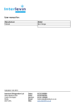
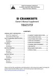
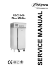
QC 11 & QC 600
Blast Chiller
&
BQCF 40 Chill / Freeze
Bakery Cabinet
Contents
Introduction
Model Details
QC 11 & QC 600 BQCF 40 Blast Chill Operating Instructions
Controller operating instructions
LED’s and there meanings
Program function and operation.
Cycle Parameter Definitions.
Cycle Parameter Access
QC 11 Cycle Parameters.
QC 600 Cycle Parameters.
BQCF 40 Cycle Parameters.
Function Menu
Parameter Access and modification
Parameter Settings
Parameter Definitions
Printer Management
Alarm Signals
Controller Electrical Connections
Technical Data
Wiring Diagram Numbers
1
Page
2
2
3
4
4
5
5
5
5 to 6
6
6 to 7
7 to 8
8
8 to 9
9 to 11
11
11
11
12
12
Introduction.
Cook Chill Operation.
Blast chilling is a process to reduce the temperature of cooked food by swiftly arresting the cooking process,
locking in its colour, flavour, texture and nutritional value. Department of health guidelines state that to safely blast
chill food the temperature must be reduced from +70°c to +3°c within 90 minutes.
Pre Chill ensures the correct cabinet temperature in the unit before chilling commences therefore improving the
chilling performance.
Program 1
Soft Chilling.
Soft chilling is the process of rapid but gentle chilling of food.
This cycle brings down the food temperature to +3°c in no more than 90 minutes without the air or food
temperature going below +2°c.
This prevents large ice crystals forming therefore maintaining the texture, consistency and appearance of food
such as vegetables, rice, pasta, custard and fruit with no dehydration or cell damage.
Program 2
Hard Chilling Time.
Hard chilling is the process of general purpose chilling using time.
This cycle brings down the food temperature to +3°c in no more than 90 minutes and is ideal for chilling meat pies,
lasagne, pasta and individually portioned meals. The air temperature for this process goes down to -15°c for the
first 70 minutes of the cycle, to extract the maximum amount of heat from the product quickly. The air temperature
then increases to +2°c for the final 30 minutes of the time to reduce surface damage and ensure quality.
Program 3
Hard Chill +
This program is for specialist chilling only and not recommended for normal use.
Program 4
Hard Chilling Temperature.
Hard chilling is the process of general purpose chilling using the food probe.
This cycle brings down the food temperature to +3°c in no more than 90 minutes and is ideal for chilling meat pies,
lasagne, pasta and individually portioned meals. The air temperature for this process goes down to -15°c for the
first 70% of the cycle, to extract the maximum amount of heat from the product quickly. The air temperature then
increases to +2°c for the final 30% of the time to reduce surface damage and ensure quality.
Longer Term Storage – ‘Hold’ Mode (Conservation)
Upon the completion of the blast chilling cycle the controller will automatically enter the ‘Hold’ mode. This will either
be because the selection set time has elapsed or the product core temperature has been achieved. When the hold
period commences an alarm will sound for a period denoted in the service operating parameters.
The controller will determine the temperature to be maintained during the hold phase based on the chilling or
freezing cycle that has been completed. If a soft or hard chill has taken place the controller will maintain an air
temperature of 2°c, if a freeze program is completed the air temperature of -21°c will be maintained.
The hold mode is principally intended as a temporary storage facility offering the operator flexibility until the product
can be unloaded into a longer term storage units at the correct storage temperature. On occasion this hold period
may become extended to operate overnight or to provide emergency refrigeration backup. In such instances
defrosting would automatically occur as necessary.
Model Details.
Cabinet Blast Chiller & Freezers.
Controls located in the unit cover.
All of the cabinet range incorporate a bottom mounted refrigeration systems with the evaporator located on the
back wall. The refrigerant used is R404a.
Door operated fan switches stop the fans when the door is opened.
QC11, QC 600 all 230/1/50Hz 13amp.
QC11: Economy Blast Chiller, 11kg capacity with three GN1/1 shelves.
QC 600: Economy Blast Chiller, 40kg capacity
BQF 40: Bakery Quick Freeze,
2
QC 11, QC 600 & BQCF 40 Blast Chill Operating Instructions.
Operation
---
When mains electrical power is first applied to the controller it will carry out a self-test function
for
approximately 3 seconds, after this the cabinet air temperature will be displayed.
To start, select the program required by pressing the program mode button (1, 2, 3,4), the LED for that mode will
illuminate, press and hold start key for three seconds to start the program. The display will show the program
time.
The compressor may pause before starting at the start of a cycle to prevent short cycling of the condensing system
and is normal.
When the time or temperature is achieved the machine will go in to the Hold mode with the sounding of an alarm.
To stop the cycle press and hold the start key
for 2 seconds, the cycle will be terminated.
Manual Defrost.
When the blast chiller is in hold press the defrost key
and hold for 2 seconds to start the defrost.
When defrost is complete the machine will revert to the hold temperature.
Program Mode
Program Type
Program
Time
Air Temperature
Chill Temperature
Hold
Temperature
SOFT
90
90 minutes @ +2°c
N/A
+3°c
HARD
90
70 minutes @ -15°c
20 minutes @ +2°c
N/A
+3°c
HARD +
240
240 minutes @ -15°c
N/A
+3°c
75% @ -15°c
25% @ +3°c
75% @ -6°c
25% @ +2°c
+3°c
HARD
IMPORTANT. Please note: Program 3 is for specialist markets only and not for normal
use.
Introduction
There are four main programmes that you will need to use your Blast Chiller.
Soft Chill- for the safe chilling of delicate products.
Hard Chill Time - For general purpose chilling based on time.
Hard Chill +-. This program is for specialist chilling only and is not recommended for normal use.
Hard Chill Temperature - For general purpose chilling using the food probe.
Guide for Blast Chilling
Food Type
Includes
Meat
Beef, pork, lamb, poultry & mince
Fried, poached or baked – haddock, plaice, salmon, cod
fillets etc
Stews & casseroles, lasagne, risotto, shepherds pie
Steamed or roasted veg, rice and potatoes etc.
Stewed and cooked fruits.
Cakes
Pastries
Fruit Based desserts & egg based flans.
Sponge puddings and dense desserts such as cheesecake.
Fish
Prepared dishes
Vegetables & Pulses
Fruit
Bakery
Bakery
Desserts
Desserts
3
Blast Chill
Programme
required
2 or 4
1
2 or 4
1
1
2 or 4
2 or 4
1
2 or 4
Controller operating instructions
DEFROST/ UP
4
3
5
2
START/ STOP
1
DOWN
SET
Display Set Point:
Press the SET key whilst in the HOLD Mode will display the set point for 5 seconds.
Modify Set Point:
Press and hold the SET key for 2 seconds. The SET point will be displayed and the LED’s
of the first and third digits will blink. To change the value, press the UP key to increase the
value or the DOWN key to decrease. To store the new value either press the SET key or
wait for the controller to return to displaying air temperature.
Manual Defrost:
Press and hold the DEFROST/UP
key for 2 seconds to initiate a manual defrost.
Starting the cycle:
Press and hold the START/STOP
key for 3 seconds.
Temporarily Stopping the Cycle:
Press and release the START/STOP
key.
The condensing system will stop and the message “Stb” will be displayed.
To restart the cycle press and release the START/STOP
key for the cycle to
continue from the point it was interrupted.
Alternatively the cycle will restart automatically after the time set in parameter PAU (see
parameter list on page ).
Stopping the Cycle:
Press and hold the START/STOP
until the display shows “End”, the buzzer will
sound and the unit will enter the stand by mode.
LED’s and there meanings
A series of LED’s, number 1 to 4, on the front panel are used to indicate certain functions controlled by the
controller. There functions are listed below.
LED
1
1
1
2
2
2
3
3
4
4
5
Mode
Illuminated
Flashing
Flashing
Illuminated
Flashing
Flashing
Illuminated
Flashing
Illuminated
Flashing
Illuminated
Function
Compressor Enabled
Programming Phase (flashing with LED 2).
Anti Short Cycle Enabled
Fan/s Enabled
Programming Phase (flashing with LED 1).
Activation Delay Active
Defrost Active
Drip Time Active
Freezing Cycle or Hold Mode Active
Instrument Temporarily Stopped
Alarm Signalling
4
5
Illuminated
When in program Pr2 indicates the parameter is also present in
Program function and operation.
Each of the programs is divided into 3 phases of operation.
Phase 1:
Hard Chill.
Phase 2:
Soft Chill.
Phase 3:
Freezing Cycle.
For each phase there are 3 parameters.
IS1 (iS2, iS3): operation controlled by the Food Probe.
RS1 (rS2, rS3): set point for the room Temperature Probe for each phase.
Pd1 (Pd2, Pd3): The maximum time duration for each phase.
Hds: hold phase set point at the end of the whole cycle.
There are also 2 parameters relating to defrost.
These are dbC = Defrost Before cycle, dbH = defrost before hold (at the end of the cycle).
Cycle Parameter Definitions.
Parameter
dbc:
First Phase
iS1
Range
yes/ no
Minimum
------------
Description
Defrost before cycle
50 to + 50°C
1°C or 1°F
rS1
50 to + 50°C
1°C or 1°F
Pd1
Second Phase
iS2
OFF to 4.0 hours
10 minutes
Food Probe Set Point (when the temperature
measured by the food probe reaches this value
the first phase is ended).
Air Temperature Set Point (prevents the air
temperature going to low during the first phase).
Maximum Time For The First Phase
50 to + 50°C
1°C or 1°F
rS2
50 to + 50°C
1°C or 1°F
Pd2
Third Phase
iS3
OFF to 4.0 hours
10 minutes
50 to + 50°C
1°C or 1°F
rS2
50 to + 50°C
1°C or 1°F
Pd3
OFF to 4.0 hours
10 minutes
yes/ no
50 to + 50°C or OFF
-----------1°C or 1°F
Food Probe Set Point (when the temperature
measured by the food probe reaches this value
the second phase is ended).
Air Temperature Set Point (prevents the air
temperature going to low during the first phase).
Maximum Time For The Second Phase
Food Probe Set Point (when the temperature
measured by the food probe reaches this value
the whole cycle is ended).
Air Temperature Set Point (prevents the air
temperature going to low during the third
phase).
Maximum Time For The Third Phase.
Defrost before the hold phase
Set Point OF The Hold Phase. If set to OFF the
hold Phase is disabled.
Important Note: If the duration time phase is set to OFF the corresponding phase is disabled.
E.G. If Pd3 = OFF the third phase of the cycle is not active.
dbH
HdS
Cycle Parameter Access
To access the cycle parameters Press and Hold the Set and Down buttons for 2 seconds.
The display will show “Prb” press the down button and scroll through until you get to “FCY” cycle management.
Press Set “Cy1” will be displayed, press the down button to scroll through the submenu to select the required
cycle parameters. Once selected press the set key to access the cycle parameters.
QC 11 Cycle Parameters.
Soft Chill- for the safe chilling of delicate products. (Cy1)
dbC = no
iS1 = -10°C
rS1 = 2°C
Pd1 = 1.3 hours
iS2 = 5°C
rS2 = -2°C
Pd2 = OFF
iS3 = 3°C
rS3 = -2°C
Pd3 = OFF
5
dbH = no
HdS = 3°C
6
Hard Chill Time - For general purpose chilling based on time. (Cy2)
dbC = no
iS1 = -15°C
rS1 = -15°C
Pd1 = 1.1hours
iS2 = 2°C
rS2 = 2°C
Pd2 = 0.2 hours
iS3 = -18°C
rS3 = -30°C
Pd3= OFF
dbH = no
HdS = 3°C
Hard Chill +-. This program is for specialist chilling only and is not recommended for normal use. (Cy3)
dbC = no
iS1 = -15°C
rS1 = -15°C
Pd1 = 4 hours
iS2 = -18C
rS2 = -30°C
Pd2 = OFF
iS3 = -18°C
rS3 = -15°C
Pd3 = OFF
dbH = no
HdS = 3°C
Hard Chill Temperature - For general purpose chilling using the food probe. (Cy4)
dbC = no
iS1 = -6°C
rS1 = -15°C
Pd1 = 1.1 hours
iS2 = 3°C
rS2 = 2°C
Pd2 = 0.2
iS3 = -18°C
RS3 = -30°C
Pd3 = OFF
dbH = no
HdS = 3°C
QC 60 Cycle Parameters.
Soft Chill- for the safe chilling of delicate products. (Cy1)
dbC = no
iS1 = -10°C
rS1 = 2°C
Pd1 = 1.3 hours
iS2 = 5°C
rS2 = -2°C
Pd2 = OFF
iS3 = 3°C
rS3 = -2°C
Pd3 = OFF
dbH = no
HdS = 3°C
Hard Chill Time - For general purpose chilling based on time. (Cy2)
dbC = no
iS1 = -15°C
rS1 = -15°C
Pd1 = 1.1hours
iS2 = 2°C
rS2 = 2°C
Pd2 = 0.2 hours
iS3 = -18°C
rS3 = -30°C
Pd3= OFF
dbH = no
HdS = 3°C
Hard Chill +-. This program is for specialist chilling only and is not recommended for normal use. (Cy3)
dbC = no
iS1 = -15°C
rS1 = -15°C
Pd1 = 4 hours
iS2 = -18C
rS2 = -30°C
Pd2 = OFF
iS3 = -18°C
rS3 = -15°C
Pd3 = OFF
dbH = no
HdS = 3°C
Hard Chill Temperature - For general purpose chilling using the food probe. (Cy4)
dbC = no
iS1 = -6°C
rS1 = -15°C
Pd1 = 1.1 hours
iS2 = 3°C
rS2 = 2°C
Pd2 = 0.2
iS3 = -18°C
RS3 = -30°C
Pd3 = OFF
dbH = no
HdS = 3°C
BQCF 40 Cycle Parameters.
Soft Chill- for the safe chilling of delicate products. (Cy1)
dbC = no
iS1 = -10°C
rS1 = 2°C
Pd1 = 1.3 hours
iS2 = 5°C
rS2 = -2°C
Pd2 = OFF
iS3 = 3°C
rS3 = -2°C
Pd3 = OFF
dbH = no
HdS = 3°C
Hard Chill Time - For general purpose chilling based on time. (Cy2)
dbC = no
iS1 = -15°C
rS1 = -15°C
Pd1 = 1.1hours
iS2 = 2°C
rS2 = 2°C
Pd2 = 0.2 hours
iS3 = -18°C
rS3 = -30°C
Pd3= OFF
7
dbH = no
HdS = 3°C
Hard Chill +-. This program is for specialist chilling only and is not recommended for normal use. (Cy3)
dbC = no
iS1 = -6°C
rS1 = -15°C
Pd1 = 1.1 hours
iS2 = 3°C
rS2 = 2°C
Pd2 = 0.2
iS3 = -18°C
rS3 = -30°C
Pd3 = OFF
dbH = no
HdS = 3°C
Hard Chill Temperature - For general purpose chilling using the food probe. (Cy4)
dbC = no
iS1 = -6°C
rS1 = -15°C
Pd1 = 1.1 hours
iS2 = 3°C
rS2 = 2°C
Pd2 = 0.2
iS3 = -18°C
RS3 = -30°C
Pd3 = OFF
dbH = no
HdS = 3°C
Function Menu
To access the cycle parameters Press and Hold the Set and Down buttons for 2 seconds.
The display will show “Prb”.
Prb: Probe Display.
Allows the probe temperatures to be displayed for ten seconds.
• rPr: Displays temperature measured by the AIR probe.
• Epr: Displays temperature measured by the EVAPORATOR probe.
• IPr: Displays temperature measured by the FOOD probe.
Press SET to display the reading of the selected probe, press SET with the reading displayed returns to the probe
labels.
Probe Fault Identification.
rPF = AIR probe fault.
EPF = EVAPORATOR probe fault.
iPF = Food probe fault.
Pr1: User Parameters.
Includes all user accessible parameters. If no parameters are present in the menu “Pr2” will be displayed.
Pr2: Installer Parameters.
Includes all the instrument parameters (at installer level). It can only be accessed using the security code. On
entering the parameters it is possible to modify all parameters and add or remove parameters from “Pr1” (user
level) by pressing “SET” + “UP”. When a parameter is enabled at user level, LED 5 (Alarm LED) is on.
Fcy: Cycle Managent.
The Fcy menu contains the Cy1, Cy2, Cy3 and Cy4 sub menus. Each of the sub menus should be set to the
Standard Cycle Parameters as detailed on pages 6 and 7.
Sto: Cycle Length.
The “Sto” menu records the real length of a cycle and the real length of each single phase. It contains the
following sub menu:
tCy: Cycle Duration. tP1: First Phase Duration. tP2: Second Phase Duration. tP3: Third Phase Duration.
rtC: Clock Managent.
Real time clock parameters.
SEC: Seconds (00 to 59).
Min: Minutes (00 to 59).
Hou: Hours (1 to 24).
7dY: Day of the week (Mon = Monday. tue = Tuesday. Wed = Wednesday. Thu = Thursday. Fri = Friday. Sat =
Saturday. Sun: Sunday)
dAY: Day of the Month (1 to 31).
Mon: Number of the month (1 to 12).
YEA: Year (0 to 99).
Alr: Alarms Display.
This function displays any alarm messages.
Prt: Printer Management.
Contains the parameters for the management of the printer.
8
PrP: Printer presence. (Yes or no) Enables or disables the printer.
ItP: Printing interval. (0.0 to 30.0). Sets the print interval.
PbP: Print probe selection. (iP: only the food probe selected. rP: only the air probe selected. irP: Food and Air
probe selected. irE: All probes selected).
PtH: (yes or no) Enables or disables the printing during the holding phase.
tSt: Starts the controller self test function.
Out: Exit from the menu.
Parameter Access and modification
To access the parameters firstly enter the function menu by pressing the “SET” and “DOWN” keys for 3 seconds.
Scroll through the labels and select “PR2”, press the “SET” key. “PAS” label flashes for a few second followed by
“0 _ _” with the zero flashing. The access code is ‘ 321’.
Use the “UP” or “DOWN” key to input the first number of the security code in the flashing section, confirm by
pressing “SET”.
Repeat the operation for the second and third digits.
If the security code is correct “Hy” will be displayed.
NOTE: if no key is pressed for 15 seconds the controller reverts to displaying the room temperature.
Parameter Settings
Lab
Description
Default
QC 11
QC 600
BQCF 40
3
2
0
0
YES
0
YES
0
°C
IN
1
2
3
60
15
10
dor
OP
5
AL
OP
60
0
2
rP
3
2
0
0
NO
0
YES
0
°C
IN
1
2
3
60
15
10
dor
OP
5
AL
CL
60
0
2
rP
3
2
0
0
YES
0
YES
0
°C
IN
1
2
3
60
15
10
dor
OP
5
AL
CL
60
0
2
rP
3
2
0
0
YES
0
YES
0
°C
IN
1
2
3
60
15
10
Dor
OP
5
AL
CL
60
0
2
rP
in
YES
6.0
20
20
rt
1
in
YES
6.0
20
20
rt
1
in
YES
6.0
20
20
rt
1
In
YES
6.0
20
20
Rt
1
c_n
30
2
2
O_Y
30
2
2
O_Y
30
2
2
O_Y
30
2
2
Regulation
Hy
AC
1c2
rPO
EPP
EPO
iPP
iPO
CF
rES
PAU
PFt
iPd
iPt
Con
COF
diC
diP
did
OAC
OAP
OAt
OAS
OAH
OAi
differential
tdF
dPO
IdF
dtE
MdF
dFd
Fdt
Defrost type
FnC
FSt
AFH
Fnd
Fan operating mode
Anti-short cycle delay
Second compressor configuration
Thermostat probe calibration
Evaporator probe presence
Evaporator probe calibration
Insert probe presence
Insert probe calibration
Temperature measurement unit
Resolution (for °C):
Time of stand by
Maximum acceptable duration of power failure
Temperature difference for the automatic recognition of the insert probe
Time delay for the automatic recognition of the insert probe
Compressor ON time with faulty probe
Compressor OFF time with faulty probe
Digital input operating mode
Digital input polarity
Digital input delay
Auxiliary output configuration
Auxiliary output polarity
AUX output timer
Set point for AUX output
Differential for AUX output
Probe selection for the AUX output
Defrost
Defrost before holding cycle
Interval between defrost cycles
Defrost termination temperature
Maximum length for defrost
Temperature displayed during defrost
Drip time
Fans
Fan stop temperature
Differential for the stop temperature and for the alarm
Fan delay after defrost
9
Alarm
ALU
ALL
ALd
EdA
tbA
MAXIMUM temperature alarm
Ad1
Ad2
Lod
rEd
LOC
PAS
tPb
rEL
Ptb
Address 1 for RS485:
Minimum temperature alarm
Temperature alarm delay
Alarm delay after defrost
Silencing alarm relay
30
30
60
30
YES
30
30
60
30
YES
30
30
60
30
YES
30
30
60
30
YES
0
1
nr
iP
no
321
ntc
1,0
--
0
1
nr
iP
no
321
ntc
1.0
--
0
1
nr
iP
no
321
ntc
1.0
--
0
1
nr
IP
No
321
Ntc
1.0
--
Others
Address 2 for RS485
Local display
Remote display
Keypad LOCK
Security code set up
Type of probe
Release code (readable only)
Parameter code (readable only)
Parameter Definitions
REGULATION
Hy Intervention differential for set point: (0,1 ÷ 12,0 /0,1°C/1°F), always positive. Compressor cut IN is Set Point
Plus Differential (Hy). Compressor cut OUT is when the temperature reaches the set point.
AC
Anti-short cycle delay: (0÷30 min) minimum interval between the compressor stop and the following
restart.
1c2 Second compressor setting: (enabled only if OAC=C2)
The fourth relay work as second compressor if OAC=Co2.
Second compressor operates on set + OAS. (whit set= set loaded during the current phase). It starts oAt min.
after the first compressor
The following table shows how it works:
Cycle
Holding
C1 ON; C2 On C1 on; C2 On
1c2=0
C1 on; C2 On C1 on C2 off
1c2=1
C1 on; C2 off
C1 on; C2 On
1c2=2
C1 on; C2 off
C1 off; C2 On
1c2=3
rPO
Thermostat probe calibration (-12,0 ÷ 12,0; res. 0,1 °C /1°F)
EPP Evaporator probe presence (not present in the XB350C): (no / YES) no: not present (timed defrost); YES:
present (end defrost )
EPO Evaporator probe calibration (not present in the XB350C): (-12,0 ÷ 12,0; res. 0,1 °C /1°F)
iPP
Insert probe presence (no / YES) no: not present; YES: present.
iPO
Insert probe calibration (-12,0 ÷ 12,0; res. 0,1 °C /1°F)
CFTemperature measurement unit: °C =Celsius; °F =Fahrenheit
rES
Resolution (for °C): in: integer; de: with decimal point
PAU Time of stand by: (0 ÷ 60min) after this time the controller restart the cycle
PFt
Maximum acceptable duration of power failure: (0 ÷ 250 min) if power failure duration is less than PFt,
the cycle restarts from the same point at which it was stopped otherwise the cycle restarts from the beginning of
the current phase.
iPd
Temperature difference for the automatic recognition of the insert probe: (0 ÷ 30; ris.1 °C/1°F) if the
difference of temperature between the insert probe and the thermostat probe is less than iPd, the selected cycle
is made by time.
iPt Time delay for the automatic recognition of the insert probe: (0÷255sec, with 0 only timed cycles are done)
time between the start of a cycle and the comparison of the temperature of the thermostat probe and the insert
probe to recognising if the insert probe is used.
Con Compressor ON time with faulty probe: (0÷ 255 min) time during which the compressor is active in case of
faulty thermostat probe. With COn=0 compressor is always OFF
COF Compressor OFF time with faulty probe: (0÷255 min) time during which the compressor is off in case of
faulty thermostat probe. With COF=0 compressor is always active
diC
Digital input operating mode (EAL, bAL, dor)
EAL: external alarm; bAL: serious alarm; dor: door open function
diP: digital input polarity: (OP÷CL)select if the digital input is activated by opening or closing the contact. OP=
opening; CL=closing
did: digital input delay (0÷255 min) delay between digital input activation and his signalling for configurable or
door opened alarm.
NOTE: with diC=EAL did has to be different from zero.
10
OAC: AUX output configuration: (AL, Li, UL, Ip, AA, rE, dF, C2)
AL: alarm output; Li: light of the cabinet; UL: for the ultra-violet light (It is actionable only when the controller is
in OFF position); Ip: to extract the insert probe (It is actionable only when the controller is in OFF position); AA:
anti - condensation; rE: the IV relay works as a thermostat, with direct action (cooling) (OAH>0), and inverse
actions (heating) (OAH<0); dF: the IV relay is activated during the defrost, at the end of the defrost it remains
ON for the OAt time; C2: second compressor. See 1c2 parameter for different settings.
OAP AUX output polarity (OP ÷ CL) OP= normally open; if it is ON the terminals 6-8 are closed. CL= normally
closed; if it is ON the terminals 6-7 are closed.
OAt
AUX output timer: (0÷255 min) time in which the AUX output stays ON. It is enabled when OAC = Li or
UL or Ip or AA or dF.
OAS Set point for AUX output (-50÷50; ris.1 °C/ 1°F)
OAH Differential for AUX output: (-12.0÷12,0; ris.0,1°C/1°F, always ≠0) Intervention differential for the set point
of the auxiliary, with OAH<0 the action is for heating, with OAH>0 it is for cooling. COOLING: AUX cut IN is
OAS Plus Differential (OAH>0). AUX cut OUT is when the temperature reaches the set point OAS.
HEATING: AUX cut IN is OAS Plus Differential (OAH<0). AUX cut OUT is when the temperature reaches the set
point OAS.
OAi
Probe selection for the AUX output (rP, EP, iP) rP = thermostat probe, EP = evaporator probe; iP =
insert probe
DEFROST
tdF
Defrost type (not present in the XB350C): (rE= electrical heater; in = hot gas).
dPO Defrost before the holding: no= no defrost; YES= defrost at the start of a holding cycle.
IdF
Interval between defrost cycles: (0.1÷ 24.0; res. 10 min) Determines the time interval between the
beginning of two defrost cycles. (with 0.0 the defrost is disabled)
dtE
Defrost termination temperature (not present in the XB350C): (-50÷50 °C/°F) Sets the temperature
measured by the evaporator probe, which terminates the defrost.
MdF Maximum length for defrost: (0÷255 min) When EPP = no (timed defrost) it sets the defrost duration, when
EPP = YES (defrost termination based on temperature) it sets the maximum length for defrost.
dFd
Temperature displayed during defrost: (rt , it, SEt, dEF) rt: real temperature; it: temperature at the start
of defrost; SEt: set point; dEF: “dEF” message
Fdt
Drip time (not present in the XB350C): (0 ÷ 60 min) Time interval between reaching defrost termination
temperature and the restoring of the controllers' normal operation. This time allows the evaporator to eliminate
water drops that might have formed during defrost.
FANS
FnC Fans operating mode during the holding phase:
C-n= runs with the compressor, OFF during defrost; o-n = continuous mode, OFF during defrost; C-Y = runs
with the compressor, ON during defrost; o-Y = continuous mode, ON during defrost;
FSt
Fan stop temperature: (-50÷50°C/°F; res. 1°C/1°F) if the temperature, detected by the evaporator probe is
above FSt fans are stopped. It serves to avoid blowing warm air around the room.
AFH Differential for the stop temperature and for the alarm (0.1 ÷ 25.0 °C; ris.0.1°C/1°F) Fans carry on working
when the temperature reaches the FSt-AFH value, the temperature alarm recovers when the temperature is
AFH degrees below the alarm set.
Fnd Fan delay after defrost: (0 ÷ 255 min) The time interval between end of defrost and evaporator fans start.
ALARM
ALU MAXIMUM temperature alarm: (1 ÷ 50 °C/°F) When the “SET+ALU” temperature is reached the alarm is
enabled, (possibly after the “Ald” delay time).
ALL Minimum temperature alarm: (1÷50°C/1°F) When the “SET-ALL” temperature is reached the alarm is
enabled, (possibly after the “Ald” delay time).
ALd Temperature alarm delay: (0÷255 min) time interval between the detection of an alarm condition and alarm
signalling.
EdA Temperature alarm delay at the end of defrost: (0 ÷ 255 min) Time interval between the detection of the
temperature alarm condition at the end of defrost and alarm signalling.
tbA Silencing alarm relay: (Yes= silencing buzzer and alarm relay, no= only buzzer silencing).
OTHER
Ad1 Address 1 for RS485: (0 ÷ 94)
Ad2 Address 2 for RS485 (0 ÷ 94)
Lod: Local display: (rP, EP, iP, nr) Select which probe is displayed by the instrument. rP: Thermostat probe.
EP: Evaporator probe. iP: Insert probe, nr: During a temperature cycle the insert probe is displayed, during the
holding phase the room probe is displayed. If the cycle is made by time the time remaining is displayed (in
minutes).
rEd
Remote display: (rP, EP, Ip) select which probe is displayed by the XR REP. rP: thermostat probe; EP:
evaporator probe; iP: insert probe.
Loc
Set point of the holding phase lock (no - YES) It locks the set point of the holding phase.
11
PAS Security code set up: (0 ÷ 999)
tPb
Type of probe: it displays the probe used (NTC or PTC) (readable only)
rEL
Release code (readable only)
Ptb
Parameter code (readable only)
Printer Management
The instrument XB570L can drive the serial printer XB05PR by means of the RS232 output. So temperatures
measured during a freezing cycle can be printed.
The internal Real Time clock of the instrument provides time reference.
The “Prt” functions manages the printer by means of the following parameters:
Prt: printer presence: (Yes/no) it enables or disables the printer.
itP: printing interval: (0.0÷30.0 min).
PbP: which probe has to be printed: (iP: Only the insert probe; rP: Only the thermostat probe; irP: Insert and
thermostat probes; irE: All the probes.
PtH: Printing during the holding phase (yES, no) yES = Printing enabled during the holding phase; no = Printing
disabled during the holding phase.
NOTE: Although the controller is capable of several features ie. HACCP recording and output, it is intentional by
Foster that these have not been developed to maintain the simplicity of operation for the end user. Therefore these
features are not offered or supported.
Alarm Signals
Mess.
Cause
“EE” Data or memory failure
Outputs
Alarm output ON; Other outputs unchanged
Alarm output ON; Compressor output according to parameters
“rPF” Thermostat Probe failure
“COn” and “COF”
Alarm output ON; Defrost termination is timed; No temperature
“EPF” Evaporator Probe failure
control on fans.
Alarm output ON; Other outputs unchanged; The cycle is made by
“iPF” Insert probe failure
time
Alarm output ON; Other outputs unchanged;
“rtC” Real Time Clock data lost
Alarm output ON; Other outputs unchanged; The date and the
“rtF” Real Time Clock failure
duration of the cycle are not available.
Alarm output ON; Other outputs unchanged.
“HA” Maximum temperature alarm
Alarm output ON; Other outputs unchanged.
“LA” Minimum temperature alarm
Alarm output ON; The freezing cycle restart from the same point at
“FF” Fast freezing interrupted by short power failure
which was interrupted.
“PFA” Fast freezing interrupted by long power failure Alarm output ON; The freezing cycle restart from the current phase.
Alarm output ON; Other outputs unchanged. In any case the cycle
“OCF” Max duration of the cycle is expired
ends when the final temperature is reached
Alarm output ON; Other outputs unchanged.
“EA” External alarm
Alarm output ON; Other outputs OFF.
“CA” Serious external alarm
Alarm output ON; Other outputs unchanged.
“dA” Door open alarm
Controller Electrical Connections
12
Technical Data
Nominal Chilling Capacity
Duty @ -15°C
Fans
Defrost Load
Evaporating Temperature
Refrigerant Control
Refrigerant
Refrigerant Quantity
Electrical Supply
Total Heat Rejection
QC11
11Kg
830w
1
N/A
-15°C
TEV
R404a
1000g
230/1/50 – 13amp
1500w
QC600
40Kg
1031w
2
N/A
-15°C
TEV
R404a
TBA
230/1/50 – 13amp
2080w
BQF 40
Wiring Diagram Numbers
Model
QC 11
QC 600
BQCsF 40
Wiring Diagram Number
01-233728
01-233729
13
Fuse Rating
13 Amp
13 Amp
13 Amp
QC 11 Wiring Diagram
QC 600 Wiring Diagram
2
BQCF 40 Wiring Diagram. Sheet 1 of 2
3
BQCF 40 Wiring Diagram. Sheet2 of 2
4
Foster European Operations
France
Foster Refrigerator France SA
Tel: (33) 01 34 30 22 22. Fax: (33) 01 30 37 68 74.
Email: [email protected]
Germany
Foster Refrigerator Gmbh,
Tel: (49) 2333 839375. Fax (49) 2333 839377.
Email: [email protected]
Foster Refrigerator
Oldmedow Road
Kings Lynn
Norfolk
PE30 4JU
Tel: 01553 691122
Fax: 01553 691447
Website: www.fosterrefrigerator.co.uk
Email: [email protected]
a Division of ‘ITW (UK) Ltd’
BC11 BC600/SM/08/04