1
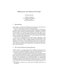
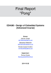
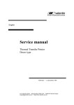
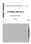
Disassembly Procedure 2 Chapter Disassembly Procedure Please follow the information provided in this section to perform the complete disassembly procedure of the notebook. Be sure to use proper tools described before. A SUS K53 Series Notebook consists of various modules. This chapter describes the procedure for the complete notebook disassembly. In addition, in between procedures, the detailed disassembly procedure of individual modules will be provided for your service needs. The disassembly procedure consists of the following steps: ◆ Battery Module ◆ Memory Module ◆ HDD Module ◆ Wireless LAN Module ◆ Keyboard Module ◆ ODD Module ◆ Top Case Module ◆ Motherboard Module ◆ LCD Module ◆ Bottom Case 2-1 V1.0 Disassembly Procedure B A T T E R Y Battery Module The illustration below shows how to remove the Battery Module. Remove Battery Module 1. Open the battery latch1, and hold the battery latch2 to take the battery away. BACK M E M O R Y Memory Module The illustration shows how to remove the Memory Module. Remove Memory Module 1. Remove 2 screws here and take the HDD door away. Remove the dummy SD card. 2-2 V1.0 Disassembly Procedure 2. Push the HDD door and take away the HDD door. 3. Pull two latches here to pop the Memory module up at 45 angles, and then pull out the module at that angle. BACK 2-3 V1.0 Disassembly Procedure H D D HDD Module The illustration shows how to remove the HDD Module. Remove HDD Module 1. Remove 4 screws on the HDD and pull back the HDD to remove it. Disassemble the HDD Module 2. Remove 4 screws on the both side of HDD housing. Separate the HDD and its housing. BACK 2-4 V1.0 Disassembly Procedure W L A N Wireless LAN Module The illustrations below show how to remove the WLAN Module. Remove the WLAN Module Remove 1 screw on the WLAN card and disconnect the 2 WLAN antennas. Pull out the card from its slot. BACK K E Y B O A R D Keyboard Module The illustrations below show how to remove the Keyboard Module. Remove the Keyboard Module 1. Open 5 latches on the keyboard module by a pair of tweezers. 2-5 V1.0 Disassembly Procedure 2. Turn over the keyboard plate and disconnect the keyboard FPC. Then remove the keyboard plate. BACK 2-6 V1.0 Disassembly Procedure O D D ODD Module The illustrations below show how to remove the ODD Module. Remove the ODD Module 1. Remove 1 screw on the top case and turn over the device to pull out the ODD. BACK T O P C A S E Top Case Module The illustrations below show how to remove and disassemble the Top Case Module. Remove the Top Case 1. Remove 6 screws on the top case and disconnect the power board FPC/touchpad FPC. Then remove 20 screws on the bottom case. 2-7 V1.0 Disassembly Procedure 2. Release the top case from the hooks around by a plastic blade. Then pry the top case and separate the top case from the bottom case. Disassemble the Top Case 3. Remove 1 screw on the power board and tear off the FPC. Take away the power board. 2-8 V1.0 Disassembly Procedure 4. Tear off the tape and disconnect the touchpad PFC. BACK M O T H E R B O A R D Motherboard Module The illustrations below show how to disassemble and remove the Motherboard Module. Remove the Motherboard Module 1. Disconnect the LVDS cable and the speaker cable. Disconnect the IO FPC from the IO board and the motherboard. Then 5 screws on the motherboard and 1 screw on the IO board. 2-9 V1.0 Disassembly Procedure 2. Take away the IO board and the motherboard from the bottom case. 3. Remove 4 screws on the thermal module by order. Disconnect the fan cable and take away the thermal module. 4 2 1 3 2 - 10 V1.0 Disassembly Procedure 4. Turn the non-removable screw 180 degrees counter-clockwise to loosen the CPU. Squeeze the vacuum handling tool to suck up the CPU and take it away. BACK L C D LCD Module The illustrations below show how to remove and disassemble the LCD Module of the notebook. Removing the LCD Module 1. Remove 5 screws on the 2 LCD hinges. Release the antennas from the guide hooks in the bottom case. 2 - 11 V1.0 Disassembly Procedure 2. Remove the LCD module from the bottom case. Disassemble the LCD Module 3. Remove 2 rubber pads and 2 screws on the LCD front bezel. Then pry the LCD bezel and take away the front bezel. 2 - 12 V1.0 Disassembly Procedure 4. Remove 8 screws on both LCD hinges. Disconnect the camera cable and release the MIC. Lift up the LCD panel and take it away. 2 - 13 V1.0 Disassembly Procedure 5. Disconnect the LVDS cable from the LCD panel. 6. Remove 4 screws on each LCD hinge. Remove the 2 LCD hinges. 2 - 14 V1.0 Disassembly Procedure 7. Remove the camera. BACK B O T T O M C A S E Bottom Case The illustrations below show how to disassemble the Bottom Case of the notebook. Disassemble the Bottom Case Remove 2 screws on the speaker. Take away the speaker from the bottom case. BACK 2 - 15 V1.0