1
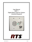
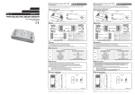
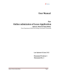
4E1 Fiber Optical Multiplexer User’s Manual TABLE OF CONTENTS 1. Product Description 1.1Function Description 1.2Features 1.3Application 1.4Specifications 2. Installation 2.1 Site Selection 2.2 Mechanical Installation 2.2.1 Double-row indicator light 2.2.2 Front panel DIP definition 2.2.3 Hot line phone (no this function in mini type) 2.2.4 Real panel 2.2.5 Power supply 3. Operation 3.1 Equipment installation 3.1.1 Quick installation 3.1.2 Coalitions about installation 3.2 Power on the equipment 3.3 Troubleshooting 4. Packaging 4.1 Packing pattern 1. Product Description 1.1 Function Description 4E1 Fiber Optical Multiplexer is the 4E1 point-to-point optical transport equipment that uses the FPGA chips and it is easy to upgrade. It is single board structure and the largest transmission capacity is 4E1. The outer design use the standard 19 inches rack, so the volume is little, weight is light and operation is convenient and credit. 4E1 Fiber Optical Multiplexer uses the PDH fiber transmission technologies. The 2M (E1) interfaces can connect with the exchanger, light loop device and multi-diplexer directly to form the macromedia or the special network. Complete alarm function for 4E1 Fiber Optical Multiplexer, it is stable and easy to maintenance, install and small in size. It has one digital service telephone. 1.2 Features Below lists the features for 4E1 Fiber Optical Multiplexer: Offer 4 ×2Mb/s digital interfaces; Up to 4E1 links on one fiber; The supervisory control interface implements centralized monitoring and export the monitor and control information of this port and opposite port. One link to service telephone for duty contract (optional); 175V-250VAC & -48VDC power options and the positive and negative of DC-48V can be optional because there is the self-test circuit for the polarity inside th1e device Standard 1U/19 inches rack or mini-type, little volume, light weight, steady capacity and convenient setup Digital clock recovery circuit and digital smooth DPLL adopted for 2.048Mb/s port LED indicators 1.3 Application 4E1 Fiber Optical Multiplexer can be used a high-speed baseband modem for point to point that connects two DTE over a lease Line. From Router CSU/DSU 4E1 Fiber Optical Multiplexer Fiber optical 4E1 Fiber Optical Multiplexer CSU/DSU DTE as illustrated in the Following Diagram. Diagram 1.1 1.4 Specification E1 line Interface Number of E1 Line Rate Line Code HDB3 Jitter tolerance 4 E1’s 2.048Mbps±50ppm HDB3 Interface Standard E1 Impedance Connector Type ITU-T G.703 120(balance) RJ45 Fine than G.742,G.823 Optical Fiber Interface Wavelength Light Source System Gain Line Code 1310 or 1550 +/- 50/40nm MLM Laser 26 dB (Min.) Scrambled NRZ Connector Type Detector PIN Input Sensitivity FC/SC Photodiode -38Dbm (Ber<10e-10) Note: Longer or shorter distance 50km or above (120km), on special order Physical/Electrical FMO-4E1-19” FMO-4E1-9.5” Dimension Height 44 mm / 1.7 in (1U), Width 485 mm /19 In Depth 160 mm / 6.3 in Height 30 mm / 1.2 in (1U) Width 222 mm /9.5 in-Depth 160 mm / 6.3 in Mounting Stand-alone,19” and 9.5” inch rack mount, wall mount also available Power Source 175 – 250 VAC ( 50H/60Hz) or –48 VDC ( -36 to –72Vdc) Power consumption <5W Temperature Range 0°C - 50°C (32° to 122°F) Relative Humidity 0% - 90%, non-condensing Diagnostics Test Loop-back testing for 4 ×E1 (Local and Remote) Loop-back testing for fiber optical (Local and Remote) Indicators Local optical signal indications for all E1s. Remote optical signal receive indication, working and loss. Loop-back indication. Alarm indication, on or off. Power on indication. 2. INSTALLATION 2.1 Site Selection This is a guideline for 4E1 Fiber Optical Multiplexer installation. The following list indicates a site selection guideline. User needs to follow this guideline for the select a proper installation site. For the 4E1 Fiber Optical Multiplexer unit, the location should be part of the Central Office (CO) equipment layout design. The entrance cable routing should consider. The installation should provide a proper room for the adequate ventilation and cable routing at site. At least 0.5 m should be reserve at the rear of the unit for the human access, cable, and airflow. The site should provide a stable environment. The Ops Area (Operating Area) should be free from extremes temperature, humidity, shock and vibration. Do not expose the unit under the rain cause 4E1 Fiber Optical Multiplexer wasn’t a waterproof unit. Relative humidity should stay between 0 and 95%. Survey the site (power supply) before install the unit. 2.2 Mechanical Installation 4E1 Fiber Optical Multiplexer is a desktop and rack mount unit, which offers two kinds of power supply AC or DC. The front panel and the rear panel are shown as below: Front Panel 2.2.1 Double-row indicator light Table 2.2.1 Name Color Status Describe 1 LOS1 Red Active E1 port 1 loss 2 LOS2 Red Active E1 port 2 loss 3 LOS3 Red Active E1 port 3 loss 4 LOS4 Red Active E1 port 4 loss 5 OPLOS Red Active Optical signal Lost 6 OPLOF Red Active Optical SYNC loss 7 PWR Green Active Power on 8 E-3 Red Active Optical BER≥10-3 Remark:Equipment have two rows indicator light Local indicate local device status Remote indicate remote device status The equipment has perfect alarm and display. The 10 LED at front panel display different alarms, voice alarms is also offered. The alarms are described as following: Power supply indicator (PWR): this light on when power is on. Local terminal alarm indicator (LOCAL): Remote terminal alarm indicator (REMOTE): Not receiving optical signal alarm indicator (OPLOS): this light on when optical detector not detect input optical signal. Sync loss alarm indicator(OPLOF): This light on when Optical sync loss. 1-4 branch E1 signal loss alarm indicator (LOS1-4): the light on when corresponding E1 signal loss. The light E-3 on when Local terminal optical BER>=10-3 2.2.2 Front panel DIP definition: Bit 1-4 (RLOOP1-4): 1-4 E1 remote loops. RLOOP1-4 as 1 to 4 port’s E1 it is to indicate loop back. If the RLOOP1 is ON, this means that at the far end the is doing a E1 loop-back For example: when RLOOP1 is on, E1 port of remote equipment loops. Bit 5: MUTE is for close alarm voice, ON is close. Bit 6: OLOOP is for optical route loop, ON is loop. OLOOP is the fiber optical Loop-back function. To set the loop-back function, push it to “ON” and it will perform a local loop back on the optical. Table 2.2.2 is all 8 DIP Switch Description DIP Function and implication SW1 Port 1 remote loop control switch SW2 Port 2 remote loop control switch SW3 Port 3 remote loop control switch SW4 Port 4 remote loop control switch SW5 Close alarm voice SW6 OLOOP (optical loop function) ON means remote loop OFF means disable remote loop ON means remote loop OFF means disable remote loop ON means remote loop OFF means disable remote loop ON means remote loop OFF means disable remote loop ON alarm voice close OFF is alarm voice Open ON is optical fiber loop OFF means Disable fiber loop SW7 Undefined SW8 Undefined Table 2.2.2 2.2.3 Rear Panel Interface AC220V 5V -48VDC TX RX 1 2 120Ω 3 4 Describe 220V AC Power In 220V AC Power Adapter In DC (-36 to -72V)IN Fiber TX Out Fiber RX In Port 1E1 Transmit (120Ω) Port2 E1 Transm it(120Ω) Port3 E1 Transm it(120Ω) Port4 E1 Transm it(120Ω) 2.2.4 Power supply 4E1 Fiber Optical Multiplexer support 3 type powers: AC220V, -48V and +24V. If the power of DC-48V is used, the positive and negative terminal can be optional because there is the self-test circuit for the polarity inside the Optical Multiplexer. 2.2.5 E1 Interface E1 Interface support 120Ω for 4E1 Fiber Optical Multiplexer Optical Multiplexer. Pin out for 120ohm as following: 3. Operation 3.1.1 Equipment installation After unpacking and before installation, make sure checking the following: Make sure the package is well. If the package is damaged, please contact our service office quickly for solution. Check the package according to the product list, if find equipment severe damaged or lack of some components, please contact installation worker or our service office. Check whether the equipment type is meeting with the type you ordered. Check whether the component is integrity. Check the power supply type. 3.1.2 Quick installation Fasten the Equipment in 19 inch. Rack with the screws in the equipment package. Use reliable ground connection at GND point of the equipment Use power tab to connect power according to the manual, don’t exchange the polarities. Create user equipment connecting wire according to your demand (2M, V.35 and 10 Base-T), then connected, don’t exchange receive and transfer wires. Connect receive and transfer optical with optical receive and transfer port of the equipment. Don’t exchanges receive and transfer wire, make sure the optical fiber head is clean, insert optical jumper, make sure connection well. (fiber bending radius≥50 mm) Use multi meter to test power polarity and voltage, make sure it match with equipment requirement. After complete installation and make sure it’s ok, power on the switch. Check indicator light meet with practice situation (see related part of manual). A clean, steady environment and firm installation should provide for independent or wall hanging equipment. 3.1.3 Cautions about installation Avoid severe libration and mechanical damage during the process of transfer and installation. Arrange fiber appropriately, fiber bending radius≥50 mm. Check voltage and polarity meet with back panel, or it will cause permanent damage to the equipment. Fiber connector can’t contaminate, wipe optical fiber head slightly using alcohol, or it will affect transmission. If the fiber connector not butt joint well, it may be cause power decline, adjust fiber connector according to practical situation. The installation position should convenience for personal pass and equipment movement. The environment should dry, clean and ventilation well. Essential static-protective is needed during the installation and maintenance, ground the chassis to increase anti-interference capability and prevent lightning strike. Before use the equipment, independence work ground and protect ground should provided, make sure it ground well. 3.2 Power on the equipment Check indicators and alarms according to manual after power on. If both local and remote work well, fiber interface connect ok, the alarm light OPLOS and OPLOF off, POWER indicator light is green. Light LOSX (X=1-4) is red and voice alarm is on because of not connecting E1 signal. After connect E1 signal, light LOSX (X=1-4) will off, voice alarm will off until all light LOSX is off. Branch shield: shield no using branch alarm; no red light is on when all alarm is off. Branch loop: when system work normally and no branch alarm happen, loop test is available with SW. put the SW switch to ON in local terminal, can control remote corresponding 2 Mb/s branch to loop, then can test corresponding output signal at local 2 Mb/s output port. Use this function you can realize loop of all the branches, and it’s easy for detect. Use bit error instrument to analyzing performance of 2M branch, and record it. Close voice alarm: voice alarm on when following situation happened: A. Optical disconnected because OPLOS alarm. B. Signal not steady cause OPLOF alarm. C. Some branches not use and not shielded. Push down SW5 at local terminal, can control closing voice alarm. Note: after failure is removed, set the button to norm, validate the alarm function 3.3 Troubleshooting Best status is configured to this equipment before out of factory, all the functional interfaces are at the front and back panel, don’t open the chassis yourself. If have failure, you can determine the range of failure using single loop, and contact our corporation. The following table list common failure and alarm, the reason may cause these alarm and solution to this alarm for you to reference. Equipment alarm and corresponding solution Table 3.3 Alarm Possible reason Solution 1 POWER off not power on Power connect not well, polarity exchanged 2 OPLOS on Not receive optical signal Optical disconnected; remote having no optical output 3 OPLOF on Not receive normal frame signal Receive signal not steady,check fiber line and equipment 4 E1 alarm Not receive 2M signal Check wire; receive and transfer are exchanged 5 Voice alarm Local alarm happened Shield when process failure 4. Packing 4.1 packing pattern Following are in the 4E1 Fiber Optical Multiplexer Package. 4E1 Fiber Optical Multiplexer ---------------------------------- 1 220AC Power Adapter------------------------------------------ 1 -48DC Power Supply-------------------------------------------- 1 User’s manual----------------------------------------------------- 1 BNC -------------------------------------------------------------- 4 We could offer detailed above fittings according to your requirements NOTE: 4E1 Fiber Optical Multiplexer is a sensitive electronic item, please do handle with extra care during delivery or shifting. This unit will be warranty for 1 year. Within the warranty period, whenever there is a problem regarding the quality issue, we will take the responsibility to repair with free. After the warranty period, we will charge accordingly depend on the fault or damage. Whenever there is a fault, try to identify the problem and the alarm. Of course, you can contact our technical support at any time.