1
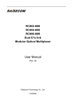
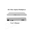
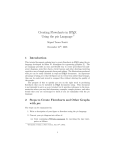
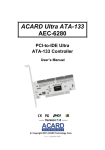
F9-480 Series 4/8/16E1 Plus Ethernet
Multi-service Multiplexer User Manual
(Version 2.1)
Beijing Fibridge Co., Ltd
4/8/16E1 Multiplexer User Manual V2.1
Table of Content
1.
Overview ..............................................................................3
2.
Features ...............................................................................3
2.1.
2.2.
3.
Typical Application..............................................................5
3.1.
3.2.
4.
Point to Point Topology ..................................................5
Star Topology .................................................................6
Specification........................................................................6
4.1.
4.2.
4.3.
4.4.
4.5.
4.6.
4.7.
4.8.
4.9.
5.
Hardware Features ........................................................3
Software Features..........................................................4
Optical Port ....................................................................6
E1 Port...........................................................................7
Ethernet Port..................................................................7
Phone Port .....................................................................7
Data Port........................................................................7
Management Port ..........................................................8
Power Supply.................................................................8
Operating Environment ..................................................9
Device Size ....................................................................9
Device Panel........................................................................9
5.1.
5.2.
5.3.
5.4.
5.5.
5.6.
5.7.
4/8E1 Multi-service Multiplexer, Standalone ..................9
16E1 Multi-service Multiplexer .....................................13
Chassis of E1 Multi-service Multiplexer .......................18
2*4E1 Multi-service Multiplexer Module .......................19
4/8E1Multi-service Multiplexer Module ........................21
EOW Module................................................................23
POW Module................................................................27
Beijing Fibridge Co., Ltd.
Tel: +8610-58858988 Fax: +8610-58858520 http://www.fibridge.com
-1-
4/8/16E1 Multiplexer User Manual V2.1
6.
Installation & Maintenance ...............................................28
6.1.
6.2.
6.3.
6.4.
7.
Install the Module and Chassis ....................................28
Install the Standalone device .......................................29
Using Phone ................................................................30
Maintenance ................................................................31
Order Information..............................................................31
7.1.
7.2.
7.3.
7.4.
Model ...........................................................................31
Part Number(P/N) of the standalone............................32
Part Number(P/N) of the Module..................................33
Part Number(P/N) of the Chassis.................................34
Beijing Fibridge Co., Ltd.
Tel: +8610-58858988 Fax: +8610-58858520 http://www.fibridge.com
-2-
4/8/16E1 Multiplexer User Manual V2.1
1. Overview
Multi-service Multiplexer combines digital multiplexing chip and
optical transmission technology. It is suitable for low capacity,
point-to-point application of remote transmission. The circuit part of
the equipment is fully digitized. The whole equipment is reliable,
stable, easy to install and maintain. It has good temperature and
voltage characteristics, complete alarm functions, one RS232/485
asynchronous interface and remote branch loop back functions. At
the same time, it can be monitored from Fi-View-MP management
software.
First of all, Multi-service Multiplexer can multiplex E1 (Up to
16E1) and Ethernet (2*10/100Mbps) signals in one fiber channel to
transmit. It is widely used in voice and data application field.
Sometimes, we use Multiplexer instead of Multi-service
Multiplexer. They have the same meaning.
2. Features
2.1. Hardware Features
z
z
z
Providing up to 16 E1 channels and two optional 10/100Mbps
Ethernet channels
Double Optical ports optional for redundant backup,
auto-alternative
With special optical module, the device can support ALS
Beijing Fibridge Co., Ltd.
Tel: +8610-58858988 Fax: +8610-58858520 http://www.fibridge.com
-3-
4/8/16E1 Multiplexer User Manual V2.1
z
z
z
z
z
z
z
z
z
(Automatic Laser Shutdown) function
E1 Line code: HDB3, compliant to G.703, G.823 and G.742.
Both the two Ethernet ports support 10/100Mbps
auto-detection, Full/Half Duplex auto-negotiation
Ethernet ports support VLAN and flow control
Complete alarm functions
Providing an RS232 /RS485 asynchronous interface
Supporting the local/remote E1 loop back
Remote branch loop back provided by software and hardware
Providing RS232 and Ethernet port for management
Standalone and chassis optional, 220VAC and –48VDC
optional
2.2. Software Features
z
z
z
z
z
z
z
Support local and remote management
Support Console, WEB and SNMP management
RS-232 DB9 male management port and 10/100Mbps RJ45
Ethernet management port available
Show details of system information, including chassis name,
location information, IP address, start-up time, software and
hardware version
View & configure the working status of local and remote device,
including connection status, speed, half/full duplex mode, port
status
Support remote loop back function, helping to find out the line
fault conveniently
A float window available for real-time alarm messages. And all
alarm messages can pop up to get more attention
Beijing Fibridge Co., Ltd.
Tel: +8610-58858988 Fax: +8610-58858520 http://www.fibridge.com
-4-
4/8/16E1 Multiplexer User Manual V2.1
z
z
z
z
z
z
Reset the system or a single local module or remote end
device via management software
Reset chassis to factory default
Show the detailed information of power supply, including
AC/DC type and running status
Support firmware updating, with the update tool and new
version firmware file download from our website.
Provide MIB file, make it easy to be integrated into the
third-party SNMP management software
Adopt the centralized management style and the tree-view
catalogue, which can manage many sets of chassis at the
same time in one single window. Meantime, it’s very easy and
clear to manage all devices even if many chassis in one
window.
3. Typical Application
3.1. Point to Point Topology
4/8/16E1
10/100M
4/8/16E1
Ethernet
Management
Multiplexer
Fiber
Multiplexer
Switch
PC
Figure1 Point to Point Topology
Beijing Fibridge Co., Ltd.
Tel: +8610-58858988 Fax: +8610-58858520 http://www.fibridge.com
-5-
4/8/16E1 Multiplexer User Manual V2.1
3.2. Star Topology
F9-100M represents standalone of the Multi-service Multiplexer
Figure2 Star Topology
4. Specification
4.1. Optical Port
z
z
z
z
z
z
z
Bit rate: 150Mb/s+/-50ppm
Wavelength: 1310nm/1550nm
Output power: -11 to -4dBm
Sensitivity: better than -36dBm
Connector: FC/SC/ST
Redundant backup optical port optional
Auto Laser shutdown (ALS) Optional
Beijing Fibridge Co., Ltd.
Tel: +8610-58858988 Fax: +8610-58858520 http://www.fibridge.com
-6-
4/8/16E1 Multiplexer User Manual V2.1
4.2. E1 Port
z
z
z
z
z
z
z
z
Data rate: 2048Kbps
Code type: HDB3
Compliant with G.703, G.704
Impedance:75Ω(Unbalanced), 120ohm(Balanced)optional
Connector: BNC(75Ω), RJ45(120ohm)
Jitter: Compliant with ITU-T G.742 and G.823
Unframed mode
Numbers: 4/8/16 optional
4.3. Ethernet Port
z
z
z
z
z
z
Compatible with IEEE802.3, IEEE802.3u
Speed: 10/100MpbsMbps
Full/Half duplex auto negotiating
Connectors: RJ-45
MDI/MDI-x auto negotiating
Ethernet port: 2 ports
4.4. Phone Port
z
z
z
z
Available for daily telephone communication
64Kbps PCM Code
When picking up the local side, the remote side rings.
One side hung up, the other side sounds busy.
4.5. Data Port
z
RS232/RS485 Protocol
Beijing Fibridge Co., Ltd.
Tel: +8610-58858988 Fax: +8610-58858520 http://www.fibridge.com
-7-
4/8/16E1 Multiplexer User Manual V2.1
z
z
For RS232, Bit rate: 4.8Kbps-115.2Kbps
Connector: DB9, male, check table1 for the definition
5 4 3 2 1
9 8 7 6
Table1 Definition of the Data DB9
2
PIN
3
1, 4
6
RS232
Protocol
Definition
5
RX
TX
7
8
9
RS485
GND
N.A.
TX-
TX+
RX-
RX+
(Z)
(Y)
(B)
(A)
4.6. Management Port
z
z
z
Type: Console management
Protocol: RS232, bit rate 9600bps or 19200bps
Connector: DB9, male, check table2 for the definition
Table2 Definition of the Management DB9
PIN
Definition
2
3
5
Others
RX
TX
GND
N.A.
4.7. Power Supply
z
z
Input voltage:
AC: 100V ~ 240V, 50/60Hz
DC: -48V
Power Consumption :5W
Beijing Fibridge Co., Ltd.
Tel: +8610-58858988 Fax: +8610-58858520 http://www.fibridge.com
-8-
4/8/16E1 Multiplexer User Manual V2.1
4.8. Operating Environment
z
z
Temperature:0℃—50℃
Humidity:95%,no condensing
4.9. Device Size
z
z
z
4/8E1 Standalone device
434mm (W) × 44mm (H) × 200mm (D)
16E1 Standalone device
434mm (W) × 44mm (H) × 234mm (D)
Chassis size
19 inch (W) × 6U (H) × 300mm (D)
5. Device Panel
5.1. 4/8E1 Multi-service Multiplexer, Standalone
5.1.1. Front Panel of 4/8E1 Multi-service Multiplexer
LEDs
Buttons Phone
Power Switch
Figure3 Front Panel of the 4/8E1 Multiplexer standalone
Beijing Fibridge Co., Ltd.
Tel: +8610-58858988 Fax: +8610-58858520 http://www.fibridge.com
-9-
4/8/16E1 Multiplexer User Manual V2.1
5.1.2. Back Panel of 4/8E1 Multi-service Multiplexer
Power IN
5th -8th E1
Ethernet
Mgt
1st-4th E1
Optical Port
Data
Figure4 Back Panel of the 4/8E1 Multiplexer standalone
5.1.3. LEDs Description of 4/8E1 Multi-service Multiplexer
Talbe3:LEDs description of the 4/8E1 Multiplexer standalone
LEDs
Color
Stat.
PWR
Green
ON
ARL
Red
ON/
Blink
OPTB
Green
ON
OPTA
Green
ON
NOPB
Red
ON
NOPA
Red
ON
Description
Power Supply OK
ARL is on When local device has any alarm. ARL
blinks when remote device has alarm but no alarm
at local device.
Optical-B work state indicator.
OPTB is on when Optical-B works.
Optical-A work state indicator.
OPTA is on when Optical-A works.
NOPB is on when no optical signals is detected by
RX of Optical-B Port.
NOPA is on when no optical signals is detected by
RX of Optical-A Port.
Beijing Fibridge Co., Ltd.
Tel: +8610-58858988 Fax: +8610-58858520 http://www.fibridge.com
- 10 -
4/8/16E1 Multiplexer User Manual V2.1
LOF
LOF
Red
ON
is
on
when
Optical
Line
loses
synchronization. IE-3 and IE-6 Alarm are masked
when LOF alarm occurs.
IE-3
Red
ON
IE-6
Red
ON
Red
ON
LOS8LOS1
1E-3 is on when optical line’s bit error rate is over
10-3.
1E-6 is on when optical line’s bit error rate is over
10-6.
LOSx (x=1~8) is on When the relevant E1
Channel Signal loses.
Ethernet2 Link/TX/RX indicator. LTR2 is on when
LTR2
Green
ON/
the Ethernet2 port of the local device links
Blink
properly, LTR2 blinks when the Ethernet2 port of
the local device is transmitting or receiving Data.
Ethernet2 Half/Full Duplex status indicator. FD2 is
FD2
Green
ON
on when the Ethernet2 port of the local device is
working at Full Duplex.
Ethernet2 10M/100M bps speed indicator. BT2 is
BT2
Green
ON
on when the Ethernet2 port of the local device is
working at 100Mbps speed.
Ethernet1 Link/TX/RX indicator. LTR1 is on when
LTR1
Green
ON/
the Ethernet1 port of the local device links
Blink
properly, LTR 1blinks when the Ethernet1 port of
the local device is transmitting or receiving data.
Ethernet1 Half/Full Duplex status indicator. FD1 is
FD1
Green
ON
on when the Ethernet1 port of the local device is
working at Full Duplex.
BT1
Green
ON
Ethernet1 10M/100M bps speed indicator. BT1 is
on when the Ethernet1 port of the local device is
Beijing Fibridge Co., Ltd.
Tel: +8610-58858988 Fax: +8610-58858520 http://www.fibridge.com
- 11 -
4/8/16E1 Multiplexer User Manual V2.1
working at 100Mbps speed.
Note: The LOF/1E-3/1E-6/LOS/LTR/SPD/FDX LEDs are corresponding to the
status of the remote device if the local/remote button is pressed down.
5.1.4. Button Description of 4/8E1 Multi-service Multiplexer
Table4 Panel Button Description of 4/8E1 Multiplexer
Type/Status
LOCAL
LOCAL/
REMOTE
REMOTE
Description
When the button of ‘Local/Remote’ is pressed
down as
, this led shows the status of
remote device. Opposite, when up as
,
the led shows the status of local device.
ALARM
ALARM/
MUTE
MUTE
When the button of ‘Alarm/Mute’ is pressed
down as
, the alarm sound is mute.
Opposite, when up as
, the device
sounds when any of the alarms occurs.
MASK
Switch
Button
When press this button once, any of the current
E1 LOS Alarm will be masked, it looks
disappear. But new E1 LOS Alarm will still
make the relevant LOS LED on.
5.1.5. Interface Description of 4/8E1 Multi-service Multiplexer
Table5 Interface Description of 4/8E1 Multiplexer
Ports
PHONE
Description
Phone Connector
Beijing Fibridge Co., Ltd.
Tel: +8610-58858988 Fax: +8610-58858520 http://www.fibridge.com
- 12 -
4/8/16E1 Multiplexer User Manual V2.1
POWER
AC/DC Power Input
ETH-2
The 2nd Ethernet port, RJ45, 10/100Mbps, Half/Full Duplex
EHT-1
The 1st Ethernet port, RJ45, 10/100Mbps, Half/Full Duplex
OPTB
Optical B, for backup function
OPTA
Optical A
E1 8-5
5th ~8th E1 Channel, DB37 Connector, connected by an adapter
E1 4-1
1st ~4th E1 Channel, DB37 Connector, connected by an adapter
Mgt
Management Console port, RS232, DB9 Connector
Data
RS232/RS485 Data port, DB9 Connector
Note: Above description is include all the ports. The ordered device maybe
haven’t some of the ports, such as optical B, 5th~8th E1 channel, etc.
5.2. 16E1 Multi-service Multiplexer
5.2.1. Front Panel of 16E1 Multi-service Multiplexer
\
LEDs
Buttons
DIP Switch
Ethernet
Phone
Power Switch
Optical Ports
Figure5 Front Panel of the 16E1 Multiplexer standalone
Beijing Fibridge Co., Ltd.
Tel: +8610-58858988 Fax: +8610-58858520 http://www.fibridge.com
- 13 -
4/8/16E1 Multiplexer User Manual V2.1
5.2.2. Back Panel of 16E1 Multiplexer
Power Input
9th–16th E1 Channel Card
1st – 8th E1 Channel Card
Figure6 Back Panel of the 16E1 Multiplexer standalone
Note: There are two types of Modules for the E1 channel. One is
8*BNC Module for 75ohm impedance, the other is 8*RJ45 Module
for 120ohm impedance. They are exchangeable.
5.2.3. LEDs of 16E1 Multi-service Multiplexer Description
Table6: LEDs Description of the 16E1 Multiplexer
LEDs
Color
Stat.
PWR
Green
ON
ARL
LOS16LOS1
Red
Red
ON/
Blink
ON
Description
Power Supply OK
ARL is on When local device has any alarm.
ARL blinks when remote device has alarm
but no alarm at local device.
LOSx (x=1~16) is on When the relevant E1
Channel Signal loses.
Ethernet1 Link/TX/RX indicator. LTR1 is on
LTR1
Yellow
ON/
Blink
when the Ethernet1 port of the local device
links
properly,
LTR
1blinks
when
the
Ethernet1 port of the local device acts, that
is, transmitting or receiving.
Beijing Fibridge Co., Ltd.
Tel: +8610-58858988 Fax: +8610-58858520 http://www.fibridge.com
- 14 -
4/8/16E1 Multiplexer User Manual V2.1
Ethernet2 Link/TX/RX indicator. LTR2 is on
LTR2
Yellow
ON/
Blink
when the Ethernet2 port of the local device
links
properly,
LTR2
blinks
when
the
Ethernet2 port of the local device acts, that
is, transmitting or receiving.
Ethernet1 10M/100M bps speed indicator.
SPD1
Green
ON
BT1 is on when the Ethernet1 port of the
local device is working at 100Mbps speed.
Ethernet2 10M/100M bps speed indicator.
SPD2
Green
ON
BT2 is on when the Ethernet2 port of the
local device is working at 100Mbps speed.
Ethernet1 Half/Full Duplex status indicator.
FDX1
Green
ON
FD1 is on when the Ethernet1 port of the
local device is working at Full Duplex.
Ethernet2 Half/Full Duplex status indicator.
FDX2
Green
ON
FD2 is on when the Ethernet2 port of the
local device is working at Full Duplex.
WORKA
Green
ON
WORKB
Green
ON
NOPA
Red
ON
NOPB
Red
ON
LOFA
Red
ON
Optical-A work state indicator.
OPTA is on when Optical-A works.
Optical-B work state indicator.
OPTB is on when Optical-B works.
NOPA is on when no optical signals is
detected by RX of Optical-A Port.
NOPB is on when no optical signals is
detected by RX of Optical-B Port.
LOFA is on when Optical-A Line loses
synchronization. IE-3 and IE-6 Alarm are
Beijing Fibridge Co., Ltd.
Tel: +8610-58858988 Fax: +8610-58858520 http://www.fibridge.com
- 15 -
4/8/16E1 Multiplexer User Manual V2.1
masked when LOFA alarm occurs.
LOFB is on when Optical-B Line loses
LOFB
Red
ON
synchronization. IE-3 and IE-6 Alarm are
masked when LOFB alarm occurs.
IE-3A
Red
ON
IE-3B
Red
ON
IE-6A
Red
ON
IE-6B
Red
ON
1E-3A is on when optical-A line’s bit error
rate is over 10-3.
1E-3B is on when optical-B line’s bit error
rate is over 10-3.
1E-6A is on when optical-A line’s bit error
rate is over 10-6.
1E-6B is on when optical-B line’s bit error
rate is over 10-6.
Note: The Work / NOP / LOF / 1E-3 / 1E-6 / LOS / LTR / SPD / FDX LEDs will
show the status of the remote device if the local/remote button is pressed
down.
5.2.4. DIP Switch SET of 16E1 Multi-service Multiplexer
Table7 DIP Switch Description of the 16E1 Multiplexer
X ON
ON OFF
OFF OFF
Selection
Forced Port A
Forced Port B
A/B Auto-select
Bit3
E1Loop back
ON: Local loop enable, OFF: Remote loop enable
Bit4
ALS setting
ON: ALS Enable, OFF: ALS Disable
Bit1,2
Optical
port
Note: X means both ON and OFF are OK.
Beijing Fibridge Co., Ltd.
Tel: +8610-58858988 Fax: +8610-58858520 http://www.fibridge.com
- 16 -
4/8/16E1 Multiplexer User Manual V2.1
5.2.5. Button Description of 16E1 Multi-service Multiplexer
Table8: Description for the Button of 16E1 Multiplexer
Type/Status
LOCAL
Description
When pressed down as
, this led shows
the status of remote device. When Pressed up
LOCAL/
REMOTE
REMOTE
as
, the led shows the status of local
device.
ALARM
When pressed down as
, the alarm sound
ALARM/
MUTE
MUTE
is mute. When pressed up as
, the device
sounds when any of the alarms occurs.
When press this button once, any of the current
MASK
Switch
E1 LOS Alarm will be masked, it looks disappear.
Button
But new E1 LOS Alarm will still make the relevant
LOS LED on.
5.2.6. Interface Description of 16E1 Multi-service Multiplexer
Table9 Interface Description of 16E1 Multiplexer
Port
Description
PHONE
Phone Connector
ETH-2
The 2nd Ethernet port, RJ45, 10/100Mbps, Half/Full Duplex
EHT-1
The 1st Ethernet port, RJ45, 10/100Mbps, Half/Full Duplex
OPTB
Optical B, for backup function
Beijing Fibridge Co., Ltd.
Tel: +8610-58858988 Fax: +8610-58858520 http://www.fibridge.com
- 17 -
4/8/16E1 Multiplexer User Manual V2.1
OPTA
Optical A
Power
AC/DC Power Input
E1 16-9
One card which can be installed into the standalone box,
E1 8-1
75ohm/120ohm Optional
Mgt
Management Console port, RS232, DB9 Connector
Data
RS232/RS485 Data port, DB9 Connector
Note: Above description is include all the ports. The ordered device maybe
haven’t some of the ports, such as optical B, ETH1& ETH2 etc.
5.3. Chassis of E1 Multi-service Multiplexer
5.3.1. Front View of the Chassis
P P
E
D D
O
H H
W
1 2
P
D
H
3
P
D
H
4
P
D
H
5
P
D
H
6
P
D
H
7
P
D
H
8
P
D
H
9
P
D
P P H
P
D D 12
W
H H /
R
P
11
10
W
R
Figure7: Slots types distributing
As shown in the above figure, there are 14 slots chassis in the
device. These 14 slots are dividing into three parts: the leftmost slot
Beijing Fibridge Co., Ltd.
Tel: +8610-58858988 Fax: +8610-58858520 http://www.fibridge.com
- 18 -
4/8/16E1 Multiplexer User Manual V2.1
is for EOW, the rightmost slot is for 220VAC PWR, the other 12
slots is for Multi-service Multiplexer Module. The 12th Multi-service
Multiplexer Module can also be installed for 220VAC PWR Module.
For -48VDC power input, user needn’t install any Power
Module. User only need to connect the -48V power input connector
to the -48VDC power source.
5.3.2. Back View of the Chassis
~220VAC
Power Input
DB37 to
8*BNC Adapter
-48V Power Input
-48V
PUSE POWER
-48V Power Switch
Figure8: Back Panel View of the Chassis
5.4. 2*4E1 Multi-service Multiplexer Module
For 2*4E1 Multi-service Multiplexer Module, one module has two
independent 4E1 Multi-service Multiplexer device. They are the
same. The two optical port is independent.
Beijing Fibridge Co., Ltd.
Tel: +8610-58858988 Fax: +8610-58858520 http://www.fibridge.com
- 19 -
4/8/16E1 Multiplexer User Manual V2.1
5.4.1. Panel sketch map of the 2*4E1 Multi-service Multiplexer
Module
2*Ethernet
2*Ethernet
Optical
Phone
Optical
Optical
2*Ethernet
RS232/485 Data
Optical
Phone
Phone
Figure9 The Panel of the 2*4E1(Left)and 8E1 Multiplexer Module
Beijing Fibridge Co., Ltd.
Tel: +8610-58858988 Fax: +8610-58858520 http://www.fibridge.com
- 20 -
4/8/16E1 Multiplexer User Manual V2.1
5.4.2. LEDs Description of the 2*4E1 Module
Table10 LEDs Description of 2*4E1 Multiplexer Module
LEDs
Color
Status
Description
ARL is on When local device has any alarm.
ARL blinks when remote device has alarm
ARL
Red
ON/
but no alarm at local device.
Blink
When button of ‘Local/Remote’ is pressed
down, this led shows the ALARM status of
remote device.
PHONE
Green
ON/
PHONE blinks When one calling but haven’t
Blink
been talking. PHONE is on When talking.
5.4.3. User Interface of the 2*4E1 Module
Table11 User interface description of the 2*4E1 Module
接口
含义
ETH1
st
The 1 Ethernet port, RJ45, 10/100Mbps, Half/Full Duplex
ETH2
The 2
OPT
Optical port
PHS
For phone, use one MDI-UTP to connect to the EOW Module
nd
Ethernet port, RJ45, 10/100Mbps, Half/Full Duplex
5.5. 4/8E1Multi-service Multiplexer Module
For 1*4E1 or 8E1 Multi-service Multiplexer Module, one module
has only one independent 4E1 or 8E1 Multiplexer device. The
second optional optical port is for redundant backup.
Beijing Fibridge Co., Ltd.
Tel: +8610-58858988 Fax: +8610-58858520 http://www.fibridge.com
- 21 -
4/8/16E1 Multiplexer User Manual V2.1
5.5.1. Panel of the 4/8E1 Multi-service Multiplexer Module
Please see Figure9 to get the detail information.
5.5.2. LEDs Description of the 4/8E1 Multiplexer Module
Table12: LEDs Description of the 4/8E1 Multiplexer Module
LEDs
Color
Status
PWR
Green
ON
Description
Power work state indicator.
PWR is ON when Power supply ok.
ARL is ON When local device has any
alarm. ARL blinks when remote device
ARL
Red
ON/
has alarm but no alarm at local device.
Blink
When
button
of
‘Local/Remote’
is
pressed down, this led shows the
ALARM status of remote device.
WORKA
Green
ON
WORKB
Green
ON
Optical-A work state indicator.
WORKB is ON when Optical-B works.
Optical-B work state indicator.
WORKA is ON when Optical-A works.
PHONE is ON When calling.
PHONE
Green
ON/
PHONE blinks When local device be
Blink
called by the remote end device or local
device call the remote end device.
Beijing Fibridge Co., Ltd.
Tel: +8610-58858988 Fax: +8610-58858520 http://www.fibridge.com
- 22 -
4/8/16E1 Multiplexer User Manual V2.1
5.5.3. User Interface of the 4/8E1 Multiplexer Module
Table13 Interface Description of the 4/8E1 Multiplexer Module
Port
Description
ETH1
The 1st Ethernet port, RJ45, 10/100Mbps, Half/Full Duplex
ETH2
The 2nd Ethernet port, RJ45, 10/100Mbps, Half/Full Duplex
OPTA
Optical A
OPTB
Optical B for redundant backup
DATA
RS232/RS485 are Both OK, DB9 connector
PHS
For phone, use one MDI-UTP to connect to the EOW Module
5.6. EOW Module
EOW Module provides two main functions. One is for giving the
Phone connected channel, the other is for Management. The EOW
Module supports two kinds of management port. One is RS232,
which gives Console management. The other is Ethernet, which
gives SNMP-based management.
For more information about the management, please check relative
software user manual.
Beijing Fibridge Co., Ltd.
Tel: +8610-58858988 Fax: +8610-58858520 http://www.fibridge.com
- 23 -
4/8/16E1 Multiplexer User Manual V2.1
5.6.1. Panel sketch map of the EOW Module
LEDs
Console Management Port
Ethernet Management Port
PHS, Connected to the PDH Module
LED panel
Buttons
Phone Jack
Figure10 The Panel map of the EOW Module
Beijing Fibridge Co., Ltd.
Tel: +8610-58858988 Fax: +8610-58858520 http://www.fibridge.com
- 24 -
4/8/16E1 Multiplexer User Manual V2.1
5.6.2. LEDs of the EOW Module
Table14 LEDs description of the EOW Module
LEDs
Color Status
PWR
Green
ON
ACT
Yellow
ON
Description
Power work state indicator.
PWR is ON when Power supply ok.
EOW work state indicator.
ACT blinks when EOW Module works properly.
Temperature alarm indicator.
TMP
Red
ON
TMP is ON When temperature of slots chassis is
over 70 ℃
LOS1LOS8
NOP
Red
ON
Red
ON
LOSx (x=1~8) is ON When the relevant E1
Channel Signal loses.
NOP is ON when no optical signals is detected by
RX of Optical Port.
LOF
LOF
Red
ON
is
ON
when
Optical
Line
loses
synchronization. IE-3 and IE-6 Alarm are masked
when LOF alarm occurs.
IE-3
Red
ON
IE-6
Red
ON
1E-3 is ON when optical line’s bit error rate is over
10-3.
1E-6 is ON when optical line’s bit error rate is over
10-6.
Ethernet x (x=1~4) Link/TX/RX indicator.
LTR1LTR4
Yellow
ON/
Blink
LTR x (x=1~4) is ON when the Ethernet port of the
local device links properly, LTR x (x=1~4) blinks
when the Ethernet1 port of the local device is
transmitting or receiving data.
Beijing Fibridge Co., Ltd.
Tel: +8610-58858988 Fax: +8610-58858520 http://www.fibridge.com
- 25 -
4/8/16E1 Multiplexer User Manual V2.1
FD1FD4
Ethernet x(x=1~4) Half/Full Duplex status indicator.
Green
ON
FD x (x=1~4) is ON when the Ethernet port of the
local device is working at Full Duplex.
SPD1SPD4
Ethernet x (x=1~4) 10M/100M bps speed indicator.
Green
ON
BT x (x=1~4) is ON when the Ethernet port of the
local device is working at 100Mbps speed.
Note: 1) LOS, NOP, LOF, 1E-3, 1E-6, LTR, FD, SPD LEDS shows the status of
the Multi-service Multiplexer Module, the Number of which is appeared on
the LED Panel.
2) For 2-port-Ethernet Multi-service Multiplexer Module, LTR3-4, FD3-4,
SPD3-4 is not available.
3) The NOP/LOF/1E-3/1E-6/LOS/LTR/SPD/FDX LEDs will show the
status of the remote device if the local/remote button is pressed down.
5.6.3. User Interface of the EOW Module
Table15 User Interface Description of the EOW
Ports
RS232
DB9, RS232 port for Console Management
RJ45, Ethernet Port for WEB/SNMP-based Management
ETH
Support 10/100M, Full/Half Duplex automation.
RJ45, Used to connect to the Multi-service Multiplexer Module to
PHS
use the PHONE
PHONE
NO.
Description
RJ11, Telephone port. Connect common telephone.
LED Panel, showing the Address of the relative Multi-service
Multiplexer Module
Beijing Fibridge Co., Ltd.
Tel: +8610-58858988 Fax: +8610-58858520 http://www.fibridge.com
- 26 -
4/8/16E1 Multiplexer User Manual V2.1
5.6.4. Button of the EOW Module
Table16 Button Description of the EOW
Button
RESET
ADDR
Description
Reset Button. Restart the EOW firmware.
Multi-service Multiplexer Module addresses select.
The Address is added by one when pressing.
When the button of ‘MUTE’ is pressed down as
MUTE
sound is mute.
Opposite, when up as
, the alarm
, the device
sounds when any of the alarms occurs.
When the button of ‘Local/Remote’ is pressed down as
LOCAL
,
this led shows the status of remote device. Opposite, when up as
/REMOT
, the led shows the status of local device.
5.7. POW Module
The POW Module is used only when the user use 220VAC Power
Input Source. When the user uses -48VDC Power Input Source, the
Power Module is not needed, for each Multi-service Multiplexer
Module has the circuit to converter -48VDC to 5VDC.
There are two kinds of POW Module. One is 75W, the other is
120W. Only for 75W POW Module, the chassis supports Power
Backup, for the 120W POW Module needs 2 slots. Commonly, the
75W POW Module is enough.
Beijing Fibridge Co., Ltd.
Tel: +8610-58858988 Fax: +8610-58858520 http://www.fibridge.com
- 27 -
4/8/16E1 Multiplexer User Manual V2.1
6. Installation & Maintenance
6.1. Install the Module and Chassis
z
z
z
z
z
z
z
Open the package, check the device and the attachment,
contradistinguish to the Packing List;
Install the Module, such as EOW, POW, Multi-service
Multiplexer Module, to the Chassis;
Connect the ports to other proper device. For example,
connect the management port to the PC or the switch, connect
the E1 port to PBX, etc.
Connect the Power input to the proper power source. NOTE,
-48VDC and 220VAC can’t be used at the same time!
Fasten the device to the proper place;
Power ON. Please check whether any unexpected LEDs (esp.
RED LEDs) are ON. However, the E1 LOS will be ON when the
E1 channel is not connected, and this will cause the general
alarm ‘ARL’ red LED on the Multi-service Multiplexer Module
becoming ON.
User can check the LEDs one the EOW to see the detail status
of the Multi-service Multiplexer Module. To do this, user should
first push the ‘ADDR’ button on the EOW Module to get the
right Address of the expected Multi-service Multiplexer Module.
Please refer to the below figure to get the actual address of
every Multi-service Multiplexer module.
Beijing Fibridge Co., Ltd.
Tel: +8610-58858988 Fax: +8610-58858520 http://www.fibridge.com
- 28 -
4/8/16E1 Multiplexer User Manual V2.1
E
01 03 05 07 09 11 13 15 17 19 21 23 P
O
W
W
R
02 04 06 08 10 12 14 16 18 20 22 24
Part A
Part B
The addresses of Both Part A and Part B are available for the
2*4E1 Multi-service Multiplexer Module. For 1*4E1 Multi-service
Multiplexer Module or 1*8E1 Multi-service Multiplexer Module, only
the address of the Part A is available.
6.2. Install the Standalone device
z
z
z
z
z
Open the package, check the device and the attachment,
contradistinguish to the Packing List;
Connect the ports to other proper device. For example,
connect the Ethernet port to the PC or the switch, connect the
E1 port to PBX, etc.
Connect the Power input to the proper power source. NOTE,
-48VDC and 220VAC can’t be used at the same time!
Fasten the device to the proper place;
Power ON. Please check whether any unexpected LEDs (esp.
RED LEDs) are ON. However, the E1 LOS will be ON when the
E1 channel is not connected, and this will cause the general
alarm ‘ARL’ red LED becoming ON.
Beijing Fibridge Co., Ltd.
Tel: +8610-58858988 Fax: +8610-58858520 http://www.fibridge.com
- 29 -
4/8/16E1 Multiplexer User Manual V2.1
6.3. Using Phone
6.3.1. From standalone to standalone
z
z
z
z
Connect Phone to the Multi-service Multiplexer device.
Pick up one phone, the other end phone will ring.
Pick up the other phone handle, talking
Busy sound will be sent when one hangs up the phone
6.3.2. From standalone to the Chassis
z
z
z
z
z
z
Connect phone to the PHONE jack of the standalone and the
EOW of the chassis
Pick up the phone of the standalone
On the Chassis end, sounds appear, and the PHONE led of
the relative Multi-service Multiplexer Module blinks.
Use one UTP to connect the PHS jack between the EOW and
the relative Multi-service Multiplexer Module
Pick up the phone connected to the EOW, talking
Busy sound will be sent when one hang up the phone
6.3.3. From Chassis to the standalone
z
z
z
z
z
Connect phone to the PHONE jack of the standalone and the
EOW of the chassis
Use one UTP to connect the PHS jack between the EOW and
the relative Multi-service Multiplexer Module
Pick up the phone connected to the EOW
The phone of the standalone rings, pick up and talk
Busy sound will be sent when one hang up the phone
Beijing Fibridge Co., Ltd.
Tel: +8610-58858988 Fax: +8610-58858520 http://www.fibridge.com
- 30 -
4/8/16E1 Multiplexer User Manual V2.1
6.4. Maintenance
z
z
z
z
z
z
All the Multi-service Multiplexer Modules support hot-swap
function
EOW Module also support hot-swap function, But we suggest
user not to plug it when power ON for long time use
Take care of the Optical port, avoid of any hurt from the laser
There maybe none problem when ARL led is ON, for unused
E1 can cause LOS and ARL led ON.
Use Local/Remote button to switch the status indication
between the local device and the remote device.
Use E1 loop to test the bit error rate of the device or the
transmitting line.
7. Order Information
7.1. Model
F9-480
4E1 8E1 16E1 Multi-service Multiplexer, Standalone or
Module
FB-CHS Fibridge’s Chassis
Detail order information, please refer to the below Part Number
(P/N).
Beijing Fibridge Co., Ltd.
Tel: +8610-58858988 Fax: +8610-58858520 http://www.fibridge.com
- 31 -
4/8/16E1 Multiplexer User Manual V2.1
7.2. Part Number(P/N) of the standalone
F9-1202-XXX23
F9-1203-XXX23
F9-1204-XXX23
F9-2402- XXX23
4E1 Multi-service Multiplexer,
redundant backup optical port
with
4E1 Multi-service Multiplexer, optical
port has ALS function
4E1 Multi-service Multiplexer, with
redundant backup optical port, and
optical port has ALS function
8E1 Multi-service Multiplexer, with
redundant backup optical port
F9-2403- XXX23
8E1 Multi-service Multiplexer, optical
port has ALS function
F9-2404- XXX23
8E1 Multi-service Multiplexer, with
redundant backup optical port, and
optical port has ALS function
F9-4802- XXX23
16E1 Multi-service Multiplexer,
redundant backup optical port
F9-4803- XXX23
16E1 Multi-service Multiplexer, optical
port has ALS function
F9-4804- XXX23
16E1 Multi-service Multiplexer, with
redundant backup optical port, and
optical port has ALS function
Beijing Fibridge Co., Ltd.
Tel: +8610-58858988 Fax: +8610-58858520 http://www.fibridge.com
- 32 -
with
4/8/16E1 Multiplexer User Manual V2.1
7.3. Part Number(P/N) of the Module
F9-120-XXX23M-2
2*4E1 Multi-service Multiplexer Module
F9-1203-XXX23M-2
2*4E1 Multi-service Multiplexer Module,
optical port has ALS function
F9-1202-XXX23M
4E1 Multi-service Multiplexer,
redundant backup optical port
F9-1203-XXX23M
4E1 Multi-service Multiplexer, optical
port has ALS function
F9-1204-XXX23M
4E1 Multi-service Multiplexer, with
redundant backup optical port, and
optical port has ALS function
F9-2402- XXX23M
8E1 Multi-service Multiplexer,
redundant backup optical port
F9-2403- XXX23M
8E1 Multi-service Multiplexer, optical
port has ALS function
F9-2404- XXX23M
8E1 Multi-service Multiplexer, with
redundant backup optical port, and
optical port has ALS function
F9-4802- XXX23M
16E1 Multi-service Multiplexer,
redundant backup optical port
F9-4803- XXX23M
16E1 Multi-service Multiplexer, optical
port has ALS function
F9-4804- XXX23M
16E1 Multi-service Multiplexer, with
redundant backup optical port, and
optical port has ALS function
Beijing Fibridge Co., Ltd.
Tel: +8610-58858988 Fax: +8610-58858520 http://www.fibridge.com
- 33 -
with
with
with
4/8/16E1 Multiplexer User Manual V2.1
Note:
z
z
120ohm impedance E1 port is optional
XXX stands for the transmit distance and optical port style.
For example, 40Km, FC port, XXX will be 04F.
Letter 23 in the above P/N means 2*10/100Mbps Ethernet
port
z
7.4. Part Number(P/N) of the Chassis
FC-912
6U height, 14 slots, up to 12 slots for Multi-service
Multiplexer Modules
FC-912-M
Management Module of the FC-912, support
SNMP-based/Console/WEB management
FP-9075A
Power Module of the FC-912, 75W, 220VAC
power input
FP-9120A
Power Module of the FC-912, 120W, 220VAC
power input
** We Reserve the right to vary descriptions and specifications
without notice due to Fibridge’s policy of continuous product
improvement**
Beijing Fibridge Co., Ltd.
Tel: +8610-58858988 Fax: +8610-58858520 http://www.fibridge.com
- 34 -