1
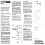
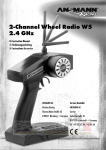
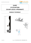
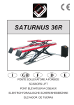
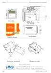
Photoelectric Beam Sensor (HP1 / HP2)
Photoelectric Beam Sensor (HP1 / HP2)
Instruction Manual
Manuale di istruzioni
Thank you for purchasing this automatic door safety beam sensor. This sensor is designed to detect intrusion to initiate
an alarm, an door controller and so on. This sensor will provide long and dependable service when properly installed.
Please read this instruction manual carefully for correct and effective use.
Grazie per aver scelto questo sensore di sicurezza a fascio per porte automatiche. Il sensore è concepito per il
rilevamento di intrusioni finalizzato all'innesco di allarmi, di centraline controllo porte, ecc. Se installato correttamente,
questo sensore garantirà un funzionamento duraturo e affidabile. Si prega di leggere attentamente il presente manuale
di istruzioni per un uso corretto ed efficace del dispositivo.
1PARTS DESCRIPTION
1DESCRIZIONE COMPONENTI
Control Box
Sensor
Scatola di comando
Operation LED
Power LED
HOTRON LTD.
Sensore
LED funzionamento
LED alimentazione
Sensor (Transmitter)
(Gray / 5m)
Sensore (Trasmettitore)
(Grigio / 5 m)
PHOTOELECTRIC BEAM SENSOR
HP1-Single / HP2-Double
Sensor (Receiver)
(Blue / 5m)
Distance adjustment
Volume
Instruction Manual
NC NO
Mounting screw
Sensore (Ricevitore)
(Blu / 5 m)
Volume regolazione
distanza
NC NO
< Default value : NO >
2WIRING
< Valore predefinito: NO >
2CABLAGGIO
POWER
(AC/DC 12V ~ 30V)
Non-polarity
Contact output
(door controller)
Control Box
L2
Scatola di comando
L2
L1
Receiver (Blue)
ALIMENTAZIONE
(CA/CC 12V ~ 30V)
Senza polarità
Uscita contatti
(centralina
controllo porta)
L2
L1
L2
L1
L1
Ricevitore (Blu)
Transmitter (Gray)
Trasmettitore (Grigio)
LED Indication
L2 Transmitter
L1 Receiver
L2 Receiver
Segnalazione LED
Ricevitore L2
Power On
Green and Red LED cross-lights up Once
Acceso
I fasci di luce del LED verde e del LED rosso si illuminano una volta
L1 Found only
Green LED lights up 5times and then Red LED On
Rilevato solo L1
Il LED verde si illumina 5 volte, poi si accende il LED rosso
L2 Found only
Red LED lights up 5times and then Red LED On
Rilevato solo L2
Il LED rosso si illumina 5 volte, poi si accende il LED rosso
L1, L2 Found
Green and Red LED light up 5times at same time
and then Red LED On
No found
Green and Red LED cross-lights up continuously
Trasmettitore L2
Ricevitore L1
L1 Transmitter
Height Min 500mm
Trasmettitore L1
Guida alla configurazione del fascio
3CAUTION
contemporaneamente, poi si accende il LED rosso
Non rilevato
I fasci di luce del LED verde e del LED rosso si illuminano continuamente
L1 o L2 interrotto
Il LED verde è acceso durante l'interruzione
3ATTENZIONE
1. Supply the power of AC/DC 12V ~ 30V only with Non-polarity
2. Do not supply the power during engineering work of installation
3. Do not disassemble or modify the device, it may cause fire or electric shock.
1. Fornire esclusivamente alimentazione CA/CC 12V ~ 30V senza polarità
2. Non fornire alimentazione durante le operazioni meccaniche di installazione
3. Non disassemblare o modificare il dispositivo perché ciò potrebbe causare incendi o scariche elettriche.
4SPECIFICATIONS
4SPECIFICHE
HP1 / HP2 (Photoelectric Beam Sensor)
HP1 / HP2 (Sensore a fascio fotoelettrico)
Transmitter & Receiver Wire
(HP1 : 2 PCS) / (HP2 : 4 PCS) 5m each
Transmitter & Receiver Sensor
(HP1 : 1EA / 1EA) / (HP2 : 2EA / 2EA)
Screw (4 x 18)
2EA
Manual
Imposta
Cavo trasmettitore e ricevitore
(HP1 : 2 PCS) / (HP2 : 4 PCS) 5 m ciascuno
Sensore trasmettitore e ricevitore
(HP1 : 1EA / 1EA) / (HP2 : 2EA / 2EA)
Vite (4 x 18)
2EA
1Copy
Manuale
1 Copia
CA/CC 12V ~ 30V (Senza polarità)
Supply voltage
AC/DC 12V ~ 30V (Non-polarity)
Tensione di alimentazione
Relay contact capacity
24V/1A
Capacità contatti relè
24V/1A
Operation Temperature
-30℃~ 55℃
Temperatura di lavoro
-30℃~ 55℃
Spec
Working distance
10m Max
Distanza di lavoro
10m Max
Current consumption
Standby 75mA / Active 100mA
Assorbimento di corrente
Standby 75 mA / Attivo 100 mA
Weight
Control box 75g / Sensor 133g (Including 5m cable)
Peso
Scatola di comando 75 g / Sensore 133 g (Incluso cavo 5 m)
5USER MANUAL
5MANUALE UTENTE
1.
2.
3.
4.
Make wiring as REF 2 and Install transmitter and receiver at the same height.
Supply power of AC/DC 12V ~ 30V and make sure that Power LED on the control box lights up
Operation LED lights up when beam is interrupted and goes out when beam is not interrupted.
Interrupt beam, and make sure that operation LED lights up and the connected devices work properly.
Note) Working distance is Min 15cm and Max 10m
In case operation LED goes off even though beam is interrupted, sensitivity may be too high.
Reduce sensitivity by turning sensitivity adjustment volume.
Make a hole ø 12mm(0.47”) and clean away the rough hole edge.
6EXTERNAL DIMENSIONS
1.
2.
3.
4.
Effettuare il cablaggio in base a quanto illustrato nel riquadro 2 e installare il trasmettitore e il ricevitore alla stessa altezza.
Fornire alimentazione CA/CC 12V ~ 30V e assicurarsi che il LED di alimentazione sulla scatola di comando sia acceso
Il LED di funzionamento si accende quando il fascio è interrotto e si spegne in caso contrario.
Interrompere il fascio, assicurarsi che i LED di funzionamento si accendano e che i dispositivi connessi
funzionino correttamente.
Nota) La distanza di lavoro minima è di 15 cm, mentre quella massima è di 10 m
Nel caso in cui il LED di funzionamento si spegnesse nonostante l'interruzione del fascio, la sensibilità
potrebbe essere troppo elevata.
Ridurre la sensibilità utilizzando il volume di regolazione della sensibilità.
Praticare un foro con diametro di 12 mm smussando poi il bordo.
6DIMENSIONI ESTERNE
Scatola di comando
Sensor
Sensore
Ø12
Ø12
Ø15
2
103,3
114,2
103,3
114,2
103,3
Control Box
103,3
Spec
14.3
Ø15
16.3
43,7
Il LED verde e il LED rosso si illuminano 5 volte
Rilevati L1, L2
Altezza minima 500 mm
L1 or L2 interrupted Green LED On while interrupted
Beam installation Guide
Set
Vite di montaggio
29,0
Ø3.5
Unit : m/m
Hotron Ltd. 26 Dublin Street, Carlow, Ireland Tel: +353 (0)59 914 0345 Fax: +353 (0)59 914 0543 www.hotron.com
2
14.3
16.3
43,7
29,0
Ø3.5
Unità: m/m
Hotron Ltd. 26 Dublin Street, Carlow, Irlanda Tel: +353 (0)59 914 0345 Fax: +353 (0)59 914 0543 www.hotron.com
Photoelectric Beam Sensor (HP1 / HP2)
Photoelectric Beam Sensor (HP1 / HP2)
Photoelectric Beam Sensor (HP1 / HP2)
Manual de instrucciones
Mode d'emploi
Anleitungen
Le agradecemos que haya adquirido este sensor automático de haz de seguridad para puertas. El sensor ha sido diseñado para
detectar intrusiones e iniciar una alarma, un controlador de puertas, etc. Este sensor puede ofrecer un servicio prolongado y
fiable si se instala correctamente. Lea atentamente este manual de instrucciones para un uso correcto y eficaz.
Nous vous remercions d'avoir acheté ce capteur de sécurité à faisceau pour portes automatiques. Ce capteur est
conçu pour détecter toute intrusion, déclenchant une alarme, un dispositif de commande de la porte, etc. L'installation
correcte de ce capteur garantit un fonctionnement fiable sur une longue durée. Veuillez lire attentivement le présent
mode d'emploi afin d'utiliser ce produit de manière correcte et efficace.
Vielen Dank, dass Sie sich zum Kauf dieses automatischen Türsicherheitsstrahlsensors entschieden haben. Dieser Sensor
wurde so konzipiert, dass er ein Eindringen erkennt, um einen Alarm, eine Türsperre oder ähnliche Aktionen auszulösen.
Bei richtigem Einbau wird dieser Sensor lange und problemlos funktionieren. Bitte lesen Sie diese Anleitungen sorgfältig durch,
um einen richtigen und effektiven Einsatz des Sensors sicherzustellen.
1DESCRIPCIÓN DE LAS PIEZAS
1DESCRIPTION DES COMPOSANTS
1TEILEBESCHREIBUNG
Caja de control
Sensor
Boîtier de commande
LED de funcionamiento
Steuerkästchen
DEL de fonctionnement
LED de alimentación
Sensor (Receptor)
(Azul / 5 m)
Tornillo de montaje
Capteur (récepteur)
(bleu/5 m)
NC NO
2CABLEADO
Stromversorgungs-LED
Capteur (transmetteur)
(gris/5 m)
Volume de réglage
de la distance
< Valor predeterminado : NO >
Vis de montage
Salida de contacto
(controlador de puerta)
Caja de control
L2
Receiver (Azul)
Boîtier de commande
< Standardwert : NO >
Steuerkästchen
L2
L1
Receiver (bleu)
STROM
(AC/DC 12 V ~ 30 V)
Ohne Polarität
Kontaktausgang
(Türkontrolle)
L2
L1
Transmisor (Gris)
L2
L1
L1
Empfänger (Blau)
Transmetteur (gris)
Sender (Grau)
LED-Anzeige
Indicadores luminosos
L2 Receptor
L2 Transmisor
L1 Receptor
L1 Transmisor
Einschalten
Grüne und rote LED blinken abwechselnd ein Mal
El LED verde se ilumina 5 veces y luego el LED rojo permanece iluminado
Nur L1 gefunden
Grüne LED blinkt 5 Mal, dann rote LED an
Sólo se encuentra L2
El LED rojo se ilumina 5 veces y luego el LED rojo permanece iluminado
Nur L2 gefunden
Rote LED blinkt 5 Mal, dann rote LED an
Transmetteur L2
Récepteur L1
Los LEDs verde y rojo se iluminan 5 veces simultáneamente
L1 o L2 interrumpidos
L1 Empfänger
Transmetteur L1
L1, L2 gefunden
Strahl-Einbauanleitung
Guide d'installation du faisceau
4CARACTÉRISTIQUES
Sensor de transmisor y receptor
(HP1 : 1EA / 1EA) / (HP2 : 2EA / 2EA)
Tornillo (4 x 18)
2EA
Manual
1 copia
Tensión de alimentación
Capacidad del relé
Temperatura de funcionamiento
Kit
Grüne und rote LED blinken kontinuierlich abwechselnd
L1 oder L2 unterbrochen Grüne LED an während Unterbrechung
4TECHNISCHE DATEN
HP1 / HP2 (Fotoelektrischer Strahl-Sensor)
Câble transmetteur et récepteur
(HP1 : 2 PCS) / (HP2 : 4 PCS) 5 m chacun
Capteur transmetteur et récepteur
(HP1 : 1EA / 1EA) / (HP2 : 2EA / 2EA)
Vis (4 x 18)
2EA
Manuel
1 copie
CA/CC 12 V ~ 30 V (Sin polaridad)
Tension d'alimentation
24V/1A
Capacité du contact de relais
-30℃~ 55℃
Température de fonctionnement
Caractéristiques
rote LED an
1. Stromversorgung AC/DC 12 V ~ 30 V nur ohne Polarität
2. Während der Einbauarbeiten darf das Gerät nicht mit Strom versorgt werden
3. Gerät nicht zerlegen oder verändern; dies könnte Brand oder Stromschlag zur Folge haben.
HP1 / HP2 (capteur à faisceau photoélectrique)
(HP1 : 2 UDS.) / (HP2 : 4 UDS.) 5 m cada uno
Grüne und rote LED blinken 5 Mal gleichzeitig, dann
3CAUTION
1. Fournissez une alimentation de 12 V ~ 30 V CA/CC uniquement sans polarité
2. N'alimentez pas le dispositif en courant pendant les travaux d'ingénierie effectués lors de l'installation
3. Ne démontez ni ne modifiez le dispositif, cela pourrait provoquer un incendie ou un choc électrique.
HP1 / HP2 (Sensor de haz fotoeléctrico)
Cable de transmisor y receptor
Keine gefunden
Höhe Min 500 mm
3ATTENTION
4ESPECIFICACIONES
Einstellen
Kabel für Sender & Empfänger
(HP1 : 2 Stk) / (HP2 : 4 Stk) je 5 m
Sensor für Sender & Empfänger
(HP1 : 1EA / 1EA) / (HP2 : 2EA / 2EA)
Schraube (4 x 18)
2EA
Anleitungen
1 Exemplar
12 V ~ 30 V CA/CC (non-polarité)
Versorgungsspannung
AC/DC 12 V ~ 30 V (Ohne Polarität)
24V/1A
Relais-Kontaktkapazität
24V/1A
-30℃~ 55℃
Betriebstemperatur
-30℃~ 55℃
Techn. Daten
Distancia operativa
Máx. 10 m
Distance de travail
10 m max.
Arbeitsabstand
10m Max
Consumo de corriente
En standby 75 mA / Activo 100 mA
Consommation électrique
Veille 75 mA / Actif 100 mA
Stromverbrauch
Standby 75 mA / Aktiv 100 mA
Peso
Caja de control 75 g / Sensor 133 g (incluido el cable de 5 m)
Poids
Boîtier de commande 75 g / Capteur 133 g (câble de 5 m inclus)
Gewicht
Steuerkästchen 75 g / Sensor 133 g (incl. 5-m-Kabel)
5MANUAL DEL USUARIO
5GUIDE D'UTILISATION
1.
2.
3.
4.
Realice el cableado conforme a REF 2 e instale el transmisor y el receptor a la misma altura.
Suministre alimentación de CA/CC de 12 V ~ 30 V y compruebe que la caja de control se ilumina
El LED de funcionamiento se ilumina cuando se interrumpe el haz y se apaga cuando no se interrumpe.
Interrumpa el haz y compruebe que el LED de operación se ilumina y que los dispositivos conectados funcionan correctamente.
Nota) La distancia operativa es de 15 cm (mín.) y 10 m (máx.)
En el caso de que el LED de funcionamiento se apague incluso cuando se interrumpe el haz,
es posible que la sensibilidad sea excesiva.
Reduzca la sensibilidad girando el volumen de ajuste de sensibilidad.
Efectúe un orificio de ø 12 mm (0,47”) y limpie la rebaba del borde del orificio.
6DIMENSIONES EXTERNAS
Utilisez le câblage comme REF 2, puis installez le transmetteur et le récepteur à la même hauteur
Fournissez une alimentation de 12 V ~ 30 V CA/CC, puis vérifiez que la DEL d'alimentation du boîtier de commande est allumée
La DEL de fonctionnement s'allume quand le faisceau est interrompu et s'éteint quand le faisceau n'est pas interrompu
Interrompez le faisceau et vérifiez que la DEL de fonctionnement s'allume et que les dispositifs connectés
fonctionnent correctement.
NB) La distance de travail est comprise entre 15 cm min. et 10 m max.
Si la DEL de fonctionnement s'éteint bien que le faisceau soit interrompu, il se peut que la sensibilité soit trop élevée.
Réduisez la sensibilité en tournant le volume de réglage de la sensibilité.
Percez un trou de ø 12 mm (0,47”), puis nettoyez le bord brut du trou.
6DIMENSIONS EXTERNES
Verkabelung gemäß REF 2 vornehmen, Sender und Empfänger in der gleichen Höhe einbauen.
Stromversorgung AC/DC 12 V ~ 30 V anschließen und prüfen, ob die Strom-LED am Steuerkästchen leuchtet
Die Betriebs-LED leuchtet, wenn der Strahl unterbrochen wird, und sie geht aus, wenn der Strahl nicht unterbrochen ist.
Strahl unterbrechen und sicherstellen, dass die Betriebs-LED leuchtet und die angeschlossenen Geräte funktionieren.
Hinweis) Der Arbeitsabstand muss zwischen 15 cm und 10 m betragen
Wenn die Betriebs-LED ausgeht, auch wenn der Strahl unterbrochen ist, wurde die
Empfindlichkeit evtl. zu hoch eingestellt.
Empfindlichkeit durch Drehen der Empfindlichkeitseinstellung verringern.
Ein 12-mm-Loch bohren und die Lochkanten entgraten.
6AUSSENABMESSUNGEN
Steuerkästchen
Sensor
Ø12
Ø12
Ø12
14.3
Ø15
Ø3.5
Unidad : m/m
Hotron Ltd. 26 Dublin Street, Carlow, Irlanda Tel: +353 (0)59 914 0345 Fax: +353 (0)59 914 0543 www.hotron.com
2
103,3
114,2
2
103,3
114,2
Ø15
103,3
Capteur
103,3
Sensor
16.3
29,0
1.
2.
3.
4.
Boîtier de commande
103,3
103,3
114,2
5BENUTZERHANDBUCH
1.
2.
3.
4.
Caja de control
43,7
L1 Sender
Hauteur 500 mm min
El LED verde permanece iluminado durante la interrupción
1. Suministre alimentación eléctrica de CA/CC 12 V ~ 30 V solamente sin polaridad
2. Interrumpa la alimentación eléctrica mientras se realizan los trabajos de instalación
3. No desmonte o modifique el dispositivo, ya que podría incendiarse o causar descargas eléctricas.
Especificación
L2 Sender
y luego el LED rojo permanece iluminado
3PRECAUCIÓN
Conjunto
L2 Empfänger
Los LEDs verde y rojo se iluminan alternadamente una vez
Sólo se encuentra L1
No se encuentra ninguno Los LEDs verde y rojo se iluminan alternadamente continuamente
Guía de instalación del haz
Récepteur L2
Encendido
Se encuentran L1, L2
Altura mínima 500 mm
Montageschraube
2VERKABELUNG
PUISSANCE
(12 V ~ 30 V CA/CC)
Non-polarité
L2
L1
L1
Sensor (Empfänger)
(Blau / 5 m)
NC NO
Sortie contact
(dispositif de
commande de
la porte)
L2
Sensor (Sender)
(Grau / 5 m)
Abstandseinstellung
Stärke
< Valeur par défaut : NO >
2CÂBLAGE
ALIMENTACIÓN
(CA/CC 12 V ~ 30 V)
Sin polaridad
Sensor
Betriebs-LED
DEL d'alimentation
Sensor (Transmisor)
(Gris / 5 m)
Volumen de ajuste
de distancia
NC NO
Capteur
14.3
Ø15
16.3
43,7
29,0
Ø3.5
Unité : m/m
Hotron Ltd. 26 Dublin Street, Carlow, Irlande Tél. : +353 (0)59 914 0345 Télécopie : +353 (0)59 914 0543 www.hotron.com
2
14.3
16.3
43,7
29,0
Ø3.5
Einheit : m/m
Hotron Ltd. 26 Dublin Street, Carlow, Ireland Tel: +353 (0)59 914 0345 Fax: +353 (0)59 914 0543 www.hotron.com