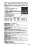
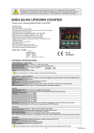
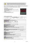
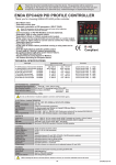
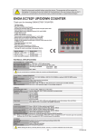
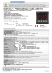
1
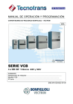
Read this document carefully before using this device. The guarantee will be expired by
damaging of the device if you don't attend to the directions in the user manual. Also we don't
accept any compensations for personal injury, material damage or capital disadvantages.
ENDA ET4410 PID TEMPERATURE CONTROLLER
Thank you for choosing ENDA ET4410 temperature controller.
* 48 x 48mm sized.
* Double set point can be selected.
* Selectable thermocouple types.
* Automatic calculation of PID parameters. (SELF TUNE).
ET 4410
The system before starting the first time,the system PID parameters should be
entered if known,otherwise Self-Tune property mustnot be operated.
C/A2
* Digital inputs can be assigned to 3 different feature.
* Function key can be assigned to 3 different feature.
* Soft-Start feature.
* Selectable analog,SSR,relay or motorized valve control output.
* Selectable 0-20mA and 4-20mA retransmission output.
* Selectable 0-20mA and 4-20mA analog control output.
* Alarm2 or temperature control output can be programmed as C/A2
relay output.
* Alarm1 output or PID cooling output can be programmed
* Selectable heating and cooling control
* For input offset feature.
* In the case of probe failure periodical running or relay state can be selected.
* Communication with RS-485 ModBus protocol.
* CE marked according to European Norms.
AN/SSR
PV
A1
SV
SET
F
C/A SET
ENDA
TEMPERATURE CONTROLLER
TECHNICAL SPECIFICATIONS
Input type
°C
J (Fe-CuNi) Thermocouple
K (NiCr-Ni) Thermocouple
T (Cu-CuNi) Thermocouple
S (Pt10Rh-Pt) Thermocouple
R (Pt13Rh-Pt) Thermocoup
EN 60584
EN 60584
EN 60584
EN 60584
EN 60584
Accuracy
Temperature range
°F
0... 600 °C
0...1300°C
0... 400°C
0...1700°C
0...1700°C
+32... +1112 °F
+32... +2372 °F
+32... +752 °F
+32... +3092 °F
+32... +3092°F
0,5% (of full scale)
0,5% (of full scale)
0,5% (of full scale)
0,5% (of full scale)
0,5% (of full scale)
1 digit
1 digit
1 digit
1 digit
1 digit
ENVIRONMENTAL CONDITIONS
Ambient/storage temperature 0 ... +50°C-25...
/
+70°C (with no icing)
Max. Relative humidity
80% up to 31°C decreasing linearly 50% at 40°C .
According to EN 60529
Front panel : IP65
Protection class
Rear panel : IP20
Height
Max. 2000m
Do not use the device in locations subject to corrosive and flammable gases.
ELECTRICAL CHARACTERISTICS
Supply
Power consumption
Wiring
Line resistance
Data retention
EMC
Safety requirements
230V AC +10% -20%, 50/60Hz or 24V AC ±10%, 50/60Hz.
Max. 5VA
Power terminal:2.5mm² screw-terminal connections.Signal terminal:1.5mm² screw-terminal
For thermocouple max.100ohm
EEPROM (minimum 10 years)
EN 61326-1: 1997, A1: 1998, A2: 2001 (Performance criterion B for standard EN 61000-4-3)
EN 61010-1: 2001 (Pollution degree 2, overvoltage category II)
OUTPUTS
C/A2 output
A1 output
ANL/SSR output
Life expectancy for relay
Relay : 250V AC, 2A (for resistive load), NO+NC (Selectable as control and Alarm2.)
Relay : 250V AC, 2A ( for resistive load), NO (Selectable as Alarm1 and cooling control)
Selectable as 0-20mA, 4-20mA analog output and logic control output
Without load switching 30.000.000 mechanical operation ; 250V AC,on the 2A resistive load 300.000,
electrical switching
CONTROL
Control type
Contro algorithm
A/D converter
Sampling time
Proportional band
Integral time
Hysteresis
Output power
Single set-point and alarm control
On-Off / P (selectable)
12 bit
500ms
Adjustable between 0% and 100%. If Pb=%0, On-Off control is selected.
Adjustable between 1 and 250 seconds.
Adjustable between 1 and 50°C/F.
The ratio of power at a set point can be adjusted between 0% and 100%
HOUSING
Housing type
Dimensions
Weight
Enclosure material
Suitable for flush-panel mounting according to DIN 43 700.
W48xH48xD87mm
Approx. 250g (after packing)
Self extinguishing plastics.
While cleaning the device, solvents (thinner, benzine, acid etc.) or corrosive materials must not be used.
ET4410-E-01
1/4
SET
C/A SET
If
F
key is pressed while holding
key,the programming mode is enabled.
F
C/A SET
Con.o.
C.s.lo.= C/A1 output.Control set value
lower limit.
Parameter value can be set between 0-
A1.S.L a1.s.l= Alarm1 set value lower limit.
0 Adjustable between 0 and A1.S.H
parameter value.
a1.s.H= Alarm1 set value upper limit.
Adjustable between A1.S,Lparameter value
and upper scale value.
F
A2.S.L
0
a2.s.l= Alarm2 set value lower limit.
Adjustable between 0 and A2.S.H
parameter value.
A2.S.H
600
a2.s.H= Alarm2 set value upper limit.
Adjustable between A2.S,Lparameter
value and upper scale value.
C.s.Hi.= C/A1 output. Control set value upper
limit.
C.s.Lo. parameter value can be set between
indicated value and the upper scale.
A1.S.H
600
C. pb
4
C. Pb = C/A1 output. Proportional band
value.
Adjustable between %0-%100.
C. Pb = %0 ise On-Off control is selected.
A1.HY a1.Hy= Hysteresis of the Alarm1 output.
2 Adjustable between 1-50°C.
A2.HY
2
a2.Hy= Hysteresis of the Alarm2
output.
Adjustable between 1-50°C.
C.Hys
2
C.Hys = Hysteresis of the C/A1 output.
Adjustable between 1-50 °C.
C. Pb=0 this parameter is seen.
A2.tP
INDE.
A2.tp = Type of Alarm2.
4 kinds of functions can be selected.
indE.= Independent alarm
dE. = Deviation alarm
bAnd = Band alarm
bAn.i =Band with inhibition
C. ti
4.0
C. ti = C/A1 output integral value.
Adjustable between 0.0-100.0 minute.
C. ti = 0.0 effect of integral disable.
C. Pb parameter is different from “0”,this
parameter appears.
A1.tp = Type of Alarm1.
6 kinds of functions can be selected.
indE.= Independent alarm
dE. =Deviation alarm
bAnd = Band alarm (Band)
bAn.i = Band with inhibition
in.Co.= A1 output independent cooling
control
rE.Co = A1 output relative cooling control
C. td
1.00
C. td = C/A1 output derivative value.
Adjustable between 0.00-25.00 minute.
C. td = 0.0 effect of derivative disable.
C. Pb parameter is different from “0”,this
parameter appears.
A1.tP.
INDE.
A1.St.
hi.
A1.st. = Alarm1 output situation.
If Alarm1 output Hi= A1 output is above the
Alarm1 set value;on.
lo= A1 output is above the Alarm1 set value;off.
A1.tP. parameter , in.Co. or rE.Co. is
selected; this parameter is not seen.
A1.Er. = Alarm1 probe failure situation.
on= A1 output probe failure;on.
off= A1 output probe failure;off.
C. Ct.
1
C. Ct. = C/A1 output period time.
Adjustable between 1-250sn.
C. Pb parameter is different from “0”,this
parameter appears.
A1.Er.
ON
C.p.st
0
C.p.st = At C/A1 Set value, C/A1 percent of
power;Adjustable between 0%-100%.
A1.PB
0
A1.Pb = A1 output,value of proportional
band.
Adjustable between 0%-100%.
A1.Pb= 0%, On-Off control is selected.
A1.tP. parameter, in.Co. or rE.Co. is
selected,this parameter is activated.
C.E.p.s.
0
C.E.P,s. = At sensor failure,C/A1 percent of
power;Adjustable between 0%-100%.
A1.ti
0
A1.ti = A1 output integral value.
Adjustable between 0.0-100.0 minute.
A1.ti = 0.0 effect of integral disable.
A1.tp. parameter, in.Co. or rE.Co. is
selected,this parameter is activated.
A1.td
0
A1.td = A1 output derivative value.
Adjustable between 0.00-25.00 minute.
A1.td = 0.00 effect of derivative disable.
A1.tp. parameter in.Co. or rE.Co. is
selected,this parameter is activated.
A1.Ct
1
A1.Ct = A1 output period time.
Adjustable between 1-250sn.
A1.tp. parameter in.Co. or rE.Co. is
selected,this parameter is activated.
s.s.t.s.
0
C.typ
HEAt
Sst =Soft starter timer set value
This parameter indicates the time to reach
set point value when the device is first
energised.Adjustable between 0 and 250
minutes.If 0 is selected, soft start feature
will be enable and the device reaches set
point value quickly.
Setting Pb = 0, sotf start feature will
be disable.
C.typ. = Control type selection.
C.typ = HEAt means heating control.
C.StA. = CooL means cooling control.
A1.ps
0
SET
A2.St.
hi.
A2.st. = Alarm2 output situation.
Hi= A2 output is above the set
value;on
lo= A2 output is above the set value;
off.
A2.Er.
ON
A2.Er. = Alarm2 probe failure
situation.
on= A2 output probe failure; on.
off= A2 output probe failure;off.
inp.t.
FE.cn.
Unit
°C
fltr.
5
F
SECU.
s.tun.
F
inp.t. = Type pf input selection.
FE.cn.= J type ,nc.nA.= K type c.cn.= T type
p10.r.=S type , P13.r.= R type
thermocouple selection.
This parameter varies when changing
some parameters.
F
s.t.Co. s.t.Co. = Self tune control.
no= Self tune is stopped.
no yES= Self tune is started.
Unit = The temperature unit.
°C= °C,°F= °F
This parameter varies when
changing some parameters.
fLtr. = Coefficient of digital filter.
Adjustable between 1 and 35.
If this parameter is 1,digital filter runs most
quick. If the parameter is 35,the filter run most
slow. The value of parameter should be
increased in interference.
C.o.sE
C-A2
C.o.sE = Control output selection
C-A2= C/A2 (Relay) output selection
SSR = SSR output selection
0-20 = 0-20mA analog output selection
4-20 = 4-20 mA analog output selection
A.Con.= Motorized valve output selection
ac.o.t.
20
Ac.ot.= Time of full opening of the motorized valve.
Adjustable between 2-300sn.
C.o.SE parameter,this parameter is set to the
selection of motored value is activated.
Ac.C.t.
25
Ac.C.t. = Motorized valve control period.
Adjustable between 1%-50%.Ac.ottime period of
the control output as a percentage of the control
value.
This parameter is how often to run the value
setting often prevents unnecessary.
C.o.SE parameter,this parameter is set to the
selection of motored value is activated.
A.o.lo.
0
A.o.Lo.= Analog output lower limit.
Adjustable between 0%-% A.o.Hi. .
C.o.SE parameter,this parameter is set to the
selection of analog output is activated.
A.o.Hi.
100
A.o.Hi.= Analog output upper limit.
Adjsutable between A.o.Lo.% - 100%.
C.o.SE parameter,this parameter is set to the
selection of analog output is activated.
offs.
0
oFFS. = Offset value.
Offset value is added to the measuring value.
This feature which is the point of measurement
due to its distance measurement probe,is used to
eliminate errors that might occur.
Adjustable between -99 - 99°C.
Normal value=0.
d.Adr.
1
D.aDr. = Device address (For RS485 connection)
Adjustable between 1-247.
This parameter is active devices with RS485
baud
0
baud = ModBus baud rate (For Rs485 connection)
Selectable off,2400,4800,9600,19200 ve 38400.
This parameter is active devices with RS485
communications option.
S.Cod.
0
S.Cod = Security menu access
code.
It should be 441.
Co.sc.
p.yEs
Cosc. =Parameter of CoN.o. menu
security level.
nonE = Invisible.
P.yEs = Modification can be done.
P. no = Only visible.
a.1. sc.
p.yEs
a.1.sc. = Parameter of al1..o.
menu security level.
nonE = Invisible.
P.yEs = Modification can be done.
P. no = Only visible.
a.2.sc.
p.yEs
a.2.sc. = Parameter of al2..o.
menu security level.
nonE = Invisible.
P.yEs = Modification can be done.
P. no = Only visible.
Co.sc.
p.yEs
Co.sc. = Parameter of Conf. menu
security level.
nonE = Invisible.
P.yEs = Modification can be done.
P. no = Only visible.
S.t.Sc.. = Parameter of S.tun..
menu security level.
nonE = Invisible.
P.yEs = Modification can be done.
S.t.sc.
p.yEs
dEF.P.
no
d.in.C.
nonE
F.kE.C.
off
R.trs.
p.yEs
Co.sc. = Parameter of Conf.
menu security level.
no = Parameter settings aren’t
changed.
d.in.C. = Digital input setting parameter.
nonE= Digital input is closed.
C2.S.A.= Digital input is active;2.set value is used.
manu. = If the digital input is activated ;manual mode
can be exceed.
dSP.o.= If the digital input is activated;temperature
indicator mode can be exceed.
F.kE.C. = Function key setting parameter.
nonE= Function key is closed.
C2.S.A.= The function key is used with the 2.set value.
manu. = Manual mode can be exceed by using the
function key.
dSP.o.= Temperature indicator mode can be exceed by
using function key.
R.trs. = Retransmission output control parameter.
off = Retransmission output is closed.
0-20 = 0-20mA Retransmission output is open.
4-20 = 4-20mA Retransmission output is open.
c.O.SE. parameter C-A2 or A.con. is
selected;this parameter is activated.
Modification Of Parameter Diagram
communications option.
A1.Ps =At A1 Set value, A1 output percent of
power.
Adjustable between 0%-100%.
A1.tp. parameter in.Co. or rE.Co. is selected,
this parameter is activated.
C/A SET
keys together.
C/A SET F
F
C.s.Hi.
600
A2SET
key and then pressing
Conf..
Al2.o.
F
C.s.Hi.
Alternatively,the same function occurs first pressing
F
Al1.o.
F
C.s.Lo.
0
SET
Entering from the programming mode to the run mode:
If no key is pressed within 20 seconds during programming mode,the data is stored automatically and the run mode is entered.
SET
C.HyS.
6
SET
C/A SET
C.HyS.
6
SET
C/A SET
C.HyS.
5
SET
C/A SET
C.HyS.
6
SET
C/A SET
SET
When holding
key, the value of parameter flashes and using
C/ASET
keys the requested value can be adjusted.
A1.Ep
0
A1.Ep = At A1 Set value,A1 output percent of
power.
Adjustable between 0%-100%.
A1.tp. parameterin.Co. or rE.Co. is selected,
this parameter is activated.
If
key is pressed and held 0.6 seconds, the value of the selected
parameter changes rapidly. If waited enough,the value increases 100 at each step.
After 1 second following the release of the key, initial condition is returned.The
same procedure is valid for the decrement key.
2/4
ET4410-E-01
TERMS
ET 4410
C/A2
(7)
AN/SSR
( 1 ) Measurement value and set value indicators(Running mode)
Parameter name and value(Programming mode)
PV
A1
( 2) Value increment key (Running and programming mode)
Parameter selection key (Programming mode)
SV
SET
F
C/A SET
ENDA
( 3 ) Value decrement key (Running and programming mode)
If only this key is pressed in normal operation,software version number is seen.
Parameter selection key (Programming mode)
( 4 ) Selectable function key (Running mode)
Menu selection key (Programming mode)
TEMPERATURE CONTROLLER
( 5 ) Control ve Alarm set selection key (Running mode)
Parameter set key (Programming mode)
( 1 ) PV and SV display
Character heights
( 2 ),( 3 ),( 4 ),( 5 ) Keypad
( 7 ) State indicator
PV 7 segment 4 digits red ,SV 7 segment 4 digit yellow LED display
PV display and SV display: 7.2 mm
Mikro switch
Control,Alarm1 and SSR outputs for 3 red LEDs.
ALARM1 AND ALARM2 OUTPUT TYPES
Independent Alarm
A1.tp.=indE
SV
Band alarm
A1.tp.= bAnd
Deviation Alarm
A1.tp= dE.
SV
ON
SV
ON
ON
OFF
OFF A1.St.= Hi
ON
ON
ON
OFF
OFF A1.St.= Lo
OFF
OFF
A1.Hy
a1,Hy
A1.Hy
SV+ASV +300
(ASV min. = beginning of scale-300
ASV max. = end of scale)
(ASV min. =-300, ASV max. = +300)
A1.St.= Hi
A1.Hy
SV-ASV
ASV
A1.St.= lo
SV+ASV
300
300
SV =Set point of CONT output
ASV = Set point of AL1 output
(ASV min. = 0, ASV max. = +300)
SV
= Set point of CONT output
ASV = Set point of alarm output
Band Alarm With Inhibition
A1,tp.= bAn.i
SV+ASV
SV+ASV
SV
SV
SV-ASV
SV-ASV
ON
OFF
ON
OFF
Beginning
Band alarm is possible
SV =Set point of CONT output
Beginning
Band alarm is possible
ASV = Set point of AL1 output (ASV min. = 0, ASV max. = 300 )
MODIFICATION OF CONTROL AND ALARM SET POINTS
ERROR MESSAGES
250
400
3 seconds later
pfa
400
SET
---C/A SET
400
SET
C/A SET
C1.SE.
400
C1.SE.
399
C1.SE.
400
C2.SE.
400
C2.SE.
399
C2.SE.
400
a1.SE.
500
a1.SE.
499
a1.SE.
500
a2.SE.
500
a2SE.
499
a2.SE.
500
3 seconds later
3 seconds later
____
400
Temperature sensor
is broken.
Temperature value is
higher than the scale.
Temperature value is
broken or over temperature.
One of the C2.S.A. parameter is set to d..in.C. or F.kE..Cthis parameter is seen.
3 seconds later
3 seconds later
3/4
C.O.SE.parameter,this parameter is set according to the SSR or analogue outputs.
ET4410-E-01
MOTORIZED VALVE CONNECTION AND ADJUSTMENT
L
N
12
OPEN
C/A2
13
AC 250V 2A
RESISTIVE LOAD
(VALVE OPEN)
A1
AC 250V 2A
RESISTIVE LOAD
(VALVE CLOSE)
14
CLOSE
15
16
Motorized valve connection as shown in the figure above. (Output values of the electrical values of the value is not suitable ignition
device,additional contactor must be connected together.) Then,this device p C.o.SE. parameter,A.con. is set to the selection of motor
value.On full time motorized value connected to a device, the Ac.o.t. parameter is entered in seconds.How often the introduction of the
value is required,this value is also entered in the Ac.C.t. parameter as a percentage of full time opening.
Minimum time between two contact output
Ac.C.t. value can be up to the period of time
Power on
Open
Close
exact opening time
SV
Depth
DIMENSIONS:
87mm
For removing the device from
the panel:
- While pressing both side of
the device in direction 1, push it
in direction 2.
1
ET 4410
C/A2
58mm
48mm
AN/SSR
PV
A1
SV
SET
ENDA
ENDA ET4410 is intended for installation
in control panels. Make sure that the device
is used only for intended purpose. The
shielding must be grounded on the instrument side.
During an installation all of the cables that are
connected to the device must be free of energy.The
device mustbe protected against inadmissible humidity,
vibrations,severe soiling and make sure that the
operation temperature is not exceeded.All input and
output lines that are not connected tothe supply
network must be laid out as shielded and twisted
cables.These cables should not be close
to the power cables or components.The installation
and electricalconnectionsmust be carried on by a
qualifiedstaff and must be according to the relevant
locally applicable regulations.
F
C/A SET
TEMPERATURE CONTROLLER
2
1
Connection
Cables
Panel cut-out
+0.6
mm
80mm
45
+0.6
mm
45
Flush mounting
clamp
51mm
Panel
Note 1) While panel mounting, additional distance required for
connection cables should be considered.
2) Panel thickness should be maximum 9mm.
3) If there is no 100mm free space at back side of the device,
it would be difficult to remove it from the panel.
CONNECTION DIAGRAM
ENDA INDUSTRIAL ELECTRONICS
ET4410-230VAC
PID TEMPERATURE CONTROLLER
1
2
3
SSR / mA
OUT
+
-
DIN
TC
4
12
5
13
6
14
7
+
-
10
11
8
9
15
16
Logic output of the instrument is not electrically
insulated from the internal circuits. Therefore,
when using a grounding thermocouple, do not
connect the logic output terminals to the ground.
ENDA INDUSTRIAL ELECTRONICS
ET4410-24VAC
PID TEMPERATURE CONTROLLER
1
2
230V AC ±10%
50/60Hz 5VA
10
C/A2
AC 250V 2A
RESISTIVE LOAD
(VALVE OPEN)
A1
AC 250V 2A
RESISTIVE LOAD
(VALVE CLOSE)
SN: XXXXXXXXX
SSR / mA
OUT
+
-
DIN
TC
4
12
5
13
6
14
7
+
-
24V AC ±10%
50/60Hz 5VA
11
3
C/A2
AC 250V 2A
RESISTIVE LOAD
(VALVE OPEN)
A1
AC 250V 2A
RESISTIVE LOAD
(VALVE CLOSE)
15
8
9
16
SN: XXXXXXXXX
Holding screw
0.4-0.5Nm
NOTE :
SUPPLY VOLTAGE
184-253V AC 10
veya
21.6-26.4V AC 11
50/60Hz 5VA
SENSOR INPUT :
Note 1) Mains supply cords shall meet the requirements
of IEC 60227 or IEC 60245.
2) In accordance with the safety regulations, the
power supply switch shall bring the identification of
the relevant instrument and it should be easily
accessible by the operator.
Fuse
F 100 mA 250V AC
Switch
Line
Neutral
Fuse should
be connected.
Use suitable compensation cables. Don't use
jointed cables. Pay attention to the polarities of the
thermocouple cables as shown in the figure right
are connected to the .
Order Code : ET4410- □□□□□□-□□
230V AC veya 24V AC
Supply
Cable size: 1,5mm²
+
For thermocouple :
TC
8
-
9
1
2
1- Supply Voltage
230VAC...230V AC
24VAC.....24V AC
2- Modbus Option
RS......RS-485 Modbus Communication
None...Don’t support RS-485 ModBus Communication
+
-
SÝSEL MÜHENDÝSLÝK ELEKTRONÝK SAN. VE TÝC. A.Þ.
Yukarý Dudullu Barbaros Cd. No:18 34775 - ÜMRANÝYE/ÝSTANBUL-TÜRKÝYE
Tel : +90 216 499 46 64 Pbx. Fax : +90 216 365 74 01
url : www.enda.com.tr
Equipment is protected throughout
by DOUBLE INSULATION.
ET4410-E-01
4/4