1
Read this document carefully before using this device. The guarantee will be expired by
damaging of the device if you don't attend to the directions in the user manual. Also we don't
accept any compensations for personal injury, material damage or capital disadvantages.
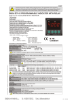
ENDA EC762F UP/DOWN COUNTER
Thank you for choosing ENDA EC762F COUNTER.
* 72x72mm sized.
* 2x6 digits display.
* Easy to use by front panel keypad.
* Counting up and down with a 2 channel inputs having 90° phase shift.
* Input frequency can be selectable.
* Prescaler factor can be adjusted between 0.001 and 99.9999.
* 6 digits Batch Counter.
* 6 digits Total Counter.
* Preset1 may depend on Preset2.
* Decimal point can be adjusted between 1. and 5. digits.
* Sensor type can be selected as PNP, NPN or Encoder.
* Double set-points control is made by 2 relays outputs.
* Output can be energized continuously or just for a time interval of 0.01
to 999.9 seconds.
* Selectable functional reset input.
* Input offset feature.
* Parameter access protection on 3 levels.
* Easy connection by removable screw terminal.
EC762F
OUT1
OUT2
BATCH
TOTAL
SET
* Having CE mark according to European Norms.
PRESET
Supply Voltage
230V AC +10% -20%
24V AC ±10%
9-30V DC SMPS module
Order Code
EC762F
EC762F-24AC
EC762F-24DC
ENDA
TOTAL
RESET
PRESET UP/DOWN COUNTER
TECHNICAL SPECIFICATIONS
ENVIRONMENTAL CONDITIONS
Ambient/storage temperature 0 ... +50°C/-25 ... +70°C (with no icing)
80% up to 31°C decreasing linearly 50% at 40°C.
Max. relative humidity
According to EN 60529
Front panel : IP60
Rated pollution degree
Rear panel : IP20
Height
Max. 2000m
Do not use the device in locations subject to corrosive and flammable gases.
ELECTRICAL CHARACTERISTICS
Supply
Power consumption
Wiring
Date retention
EMC
Safety requirements
230V AC +%10 -%20, 50/60Hz or 24V AC ±%10, 50/60Hz or optional 9-30V DC SMPS module.
Max. 7VA
2.5mm² screw-terminal connections
EEPROM (Min. 10 years)
EN 61326-1: 1997, A1: 1998, A2: 2001 (Performance criterion B for the EMC standard)
EN 61010-1: 2001 (pollution degree 2, overvoltage category II)
INPUTS
Count inputs (CP1, CP2)
Frequency (Hz)
Minimum On ans Off times
for pulses
Reset input
2 channels (Max. 7500Hz, 5V to 30V pulse)
25, 500, 1000, 2000, 5000, 7500Hz (selectable by programming)
20ms for f=25Hz
1ms for f=500Hz
500ms for f=1kHz
250ms for f=2kHz
100ms for f=5kHz
67ms for f=7,5kHz
PNP: Positive reset (5V to 30V pulse with adjustable pulse time between 2ms and 50ms)
NPN: GND terminal is connected to the RESET IN terminal.
OUTPUTS
Relay : 250V AC, 2A (for resistive load), NO+NC
Open collector output (S.S. OUT1): Max. 30V DC, 100mA.
Relay : 250V AC, 2A (for resistive load), NO+NC
Control output (OUT2)
Open collector output (S.S. OUT2): Max. 30V DC, 100mA.
12V DC, Max. 50mA (without regulation)
Auxiliary power supply
Mechanical 30.000.000 operation; Electrical 300.000 operation.
Life expectancy for relays
Note : Relay and S.S.OUT outputs are in synchronization . When OUT1 relay is energized S.S. OUT1 transistor goes into saturation.
Similarly, when OUT2 relay is energized S.S. OUT2 transistor goes into saturation.
Control output (OUT1)
HOUSING
Housing type
Dimensions
Weight
Enclosure material
Suitable for flush-panel mounting according to DIN 43 700.
W72xH72xD97mm
Approx. 405g (after packing)
Self extinguishing plastics
While cleaning the device, solvents (thinner, benzine, acid etc.) or corrosive materials must not be used.
1/5
EC762F-E-04
TERMS
EC762F
(1) The value of the parameter selected by disp. parameter during run mode.
config
Parameter name during programming mode.
OUT1
OUT2
BATCH
(2) The value of the parameter selected by disp. parameter during run mode.
config
Parameter value during programming mode.
(3) State indicators shows the state of the counter.
(4) To see the total result press this key in the run mode.
Increment or parameter selection key during programming mode.
(5) Reset key in the run mode.
Decrement or parameter selection key during programming mode
(6) Used for selecting preset value in the run mode.
Used for selecting oPtion. s or parameter to be changed in the programming mode.
(7) Used for selecting run or programming modes or for adjusting parameters.
TOTAL
SET
TOTAL
PRESET
ENDA
RESET
PRESET UP/DOWN COUNTER
( 1 ) Digital display
( 2 ) Digital display
6 digits, seven segment red LED
6 digits, seven segment yellow LED
Digital display (1) : 9.1mm
Digital display (2) : 7.1mm
4 red LEDs
Character height
( 3 ) State indicators
( 4 ),( 5 ),( 6 ),( 7 ) Keypad
Micro switch
DIMENSIONS
Panel cut-out
75mm
97mm
+0.7
1
68
mm
OUT2
BATCH
TOTAL
68
OUT1
+0.7
mm
EC762F
78mm
72mm
Depth
2
SET
PRESET
TOTAL
RESET
PRESET UP/DOWN COUNTER
84mm
ENDA
Connection
cables
For removing mounting clamps:
- Push up the flush-mounting
clamp in direction 1 as
shown in the figure above.
- Then, pull out the clamp in
direction 2.
Note 1) While panel mounting, additional distance required for
connection cables should be considered.
2) Panel thickness should be maximum 10mm.
3) If there is no 90mm free space at back side of the device,
it would be difficult to remove it from the panel.
Flush mounting
clamp
Panel
Rubber packing
CONNECTION DIAGRAM
ENDA EC762F is intended for installation in control panels. Make sure that the device is used only for intended
purpose. The shielding must be grounded on the instrument side. During an installation, all of the cables that are
connected to the device must be free of energy. The device must be protected against inadmissible humidity,
vibrations, severe soiling and make sure that the operation temperature is not exceeded. All input and output
lines that are not connected to the supply network must be laid out as shielded and twisted cables. These cables
should not be close to the power cables or components. The installation and electrical connections must be
carried on by a qualified staff and must be according to the relevant locally applicable regulations.
11
230V AC +10% -20%
50/60Hz 7VA
11
24V AC ±10%
50/60Hz 7VA
12
13
4 RESET IN
OUT1
AC 250V 2A
RESISTIVE
LOAD
13
14
4 RESET IN
OUT1
AC 250V 2A
RESISTIVE
LOAD
15
5 S.S. OUT2
6 S.S. OUT1 OUT2
AC 250V 2A
RESISTIVE
7 CP2 INPUT LOAD
9 GND
10 +12V 50mA
14
15
NOTE :
Fuse
F 100 mA
250V AC
SUPPLY :
184-253V AC 11
50/60Hz 7VA 12
Switch
Line
Neutral
230V AC Supply
Fuse should
be connected.
Cable size: 1,5mm²
5 S.S. OUT2
16
8 CP1 INPUT
12
17
18
ENDA
INDUSTRIAL
ELECTRONICS
EC762F
SN: XXXXXXXXX
16
6 S.S. OUT1 OUT2
AC 250V 2A
RESISTIVE
7 CP2 INPUT LOAD
8 CP1 INPUT
9 GND
10 +12V 50mA
17
18
ENDA
INDUSTRIAL
ELECTRONICS
EC762F-24AC
SN: XXXXXXXXX
2/5
Note : 1) Mains supply cords shall meet the requirements of IEC 60227
or IEC 60245.
2) In accordance with the safety regulations, the power supply
switch shall bring the identification of the relevant instrument
and it should be easily accessible by the operator.
Holding screw 0.4-0.5Nm
Equipment is protected throughout
by DOUBLE INSULATION.
EC762F-E-04
PrSEt1
PrSEt2
OuTPuT oPTIoN.
First preset value.
See NOTE 1 for modification.
100000
Second preset value.
See NOTE 1 for modification.
150000
SET
SET
if
key is pressed while holding
key, the
PRESET
PRG
programming mode is entered.
ýnPut
OutPut
oPtýon.
oPtýon.
PRESET
RESET
There are seven different
input types. A schematic diagram of
counting modes according to the input
types is at the next page.
See NOTE 2 for modification.
ýnPut
typE
dýr.
RESET
ýnPut
CP2-UP
CP2-Gt.
CP2.dir.
dirEct
oPPoS.
25
Hert.
500
Hert.
inPut
Frq.
1000
Hert.
UP
Ph-4
5000
Hert.
2000
Hert.
SEnSor
tyPE
nPn
PnP
rESEt
PuLS
0.002
second
0.005
second
0.010
second
0.020
second
0.050
second
outPut
typE
conFiG.
1
conFiG.
2
conFiG.
3
conFiG.
4
conFiG.
5
out1
ti.
000.0
............
999.9
out2
ti.
000.0
.............
999.9
tot.Cr.
conFiG.
diSAb.
inPut
Countr.
inPut
out1
tý.
RESET
PrSEt1.
Equ.
Pr2.Sub.
PrSEt1.
Pr1.
tý.
dEcý.
Poýnt
RESET
dýsP.
CAL.
tot.Cr.
conFiG.
8
conFiG.
9
conFiG.
10
conFiG.
bAtch
0
..............
500000
diSP.
config
Countr.
PrSEt1
Countr.
PrSEt2
Countr.
bAtch
SECUr.
codE
1111
inP.opt
SECUR.
nonE
Prog.
no
Prog.
yES
out.opt.
SECUR.
inPut = Counter input is selected as Totalizer counter input.
Countr.
RESET
oFFSEt
dAtA
Prog.
no
Prog.
yES
nonE
Prog.
yES
Count.
rESEt
no
PAnEL
rESEt
rESEt
inPut
totAL.
rESEt
no
PAnEL
rESEt
bAtch
rESEt
no
PAnEL
rESEt
dEFAuL.
SEt.
no
yES
Calibration (Prescaler) value can be adjusted between
0.00001 and 99.9999. Counter multiplies the number of
pulses by the prescaler value and the result is displayed
on the screen.
See NOTE 1 for modification.
See NOTE 3 for changing the position of the decimal point.
dýsP.
out
= Upper display shows counting value,
lower display shows PrSEt1 value.
= Upper display shows counting value,
lower display shows PrSEt2 value.
= Upper display shows counting value,
lower display shows bAtch value.
Countr.
bAtch
PrSEt1 = Output is energized when counter reaches PrSEt1 value.
Pr2.Sub. = The difference between PrSEt2 and PrSEt1 becomes the new
Pr1.
value of PrSEt1'. It means PrSEt1 (new) = PrSEt2 - PrSEt1(old)
Now, output is energized when counter reaches PrSEt1(new) value.
SECUr.
codE
RESET
ýnP.opt.
SECUR.
out.opt.
SECUR.
RESET
Countr.
PrSEt1
= Totalizer counts out2 .
See NOTE 2 for modification.
oPtýon.
RESET
offset value can be adjusted between 0 and 500000.
It means counter starts counting from the offset value
when it is reset.
See NOTE 1 for modification.
inPut
out2
bAtch
PrSEt2
= Upper display shows bAtch value,
lower display shows PrSEt2 value.
PrSET1
bAtch
= Upper display shows PrSEt1 value,
lower display shows bAtch value.
totAL.h
totAL.L
= Upper display shows maximum totAL counter
value,
lower display minimum totAL counter value.
See NOT 2 for modification.
dýs.opt.
SECUR.
and
keys together.
SET
SET
PRESET
1.00000
PRESET
1.00000
SET
key and use
NOTE 3 To change the position of the decimal point press and hold both
reset
both
RESET
totAL
rESEt
= No menu is seen.
= Menu is seen but can not be programmed.
Prog.
yES
= Menu is seen and programming is possible.
See NOT 2. for modification.
nonE
= No menu is seen.
= Menu is seen but can not be programmed.
Prog.
no
Prog.
yES
= Menu is seen and programming is possible.
See NOT 2. for modification.
nonE
= No menu is seen.
= Menu is seen but can not be programmed.
Prog.
no
reSEt
inPut.
= Menu is seen and programming is possible.
See NOT 2. for modification.
= Counter can not be reset.
= Counter can be reset by
RESET
key.
= Counter can be reset by the RESET input.
reset
= Both RESET input and the
key can
RESET
both
be used for resetting.
See NOTE 2. for modification.
no
= totAL counter can not be reset.
PAnEL
rESEt
= totAL counter can be reset by
key.
RESET
See NOTE 2. for modification.
1.01000
1.00000
RESET
keys.
RESET
dEfaul.
SET
and
Prog.
no
Count.
rESEt
RESET
SET
NOTE 2 To modify non-mumerical parameters, hold
nonE
rESEt
bAtch
RESET
SET
totAL.h
totAL.L
Access code for entering security option menu.
This parameter should be 1111.
See NOTE 2 for modification.
no
PAnE.
reSEt
RESET
RESET
key. And then, press both
RESET
1.00000
PrSEt1
bAtch
key, the value of the selected parameter can be changed by
SET
SET
bAtch
PrSEt2
PRESET
Prog.
yES
SET
keys. In order to reset all the digits, first press and hold
99.9999
RESET
= Totalizer counts out1 .
key the value of the selected parameter is seen on the display. While holding
0.00000
Prog.
no
RESET
PARAMETER MODIFICATION DIAGRAM
using
.............
nonE
Decimal point can be adjusted between 1. and 5. digits.
If desired, decimal point is not included.
See NOTE 2 for modification.
Countr.
PrSEt2
PrSEt1.
0.0
diS.opt.
SECUR.
PRESET
inPut
out1
SET
Selected
numerical
parameter
conFiG.
7
0.00001 .............
oFFSEt
dAtA
RESET
See NOTE 2 for modification.
PRESET
conFiG.
6
0
diSP.
CAL.
RESET
diSAb. = Totalizer counter parameter becomes active.
Equ.
NOTE 1 Holding
7500
Hert.
dEci.
Point
SECUr.
RESET
Puls
Ph-2
oPtýon.
Out2 energizing time can be adjusted between 000.0 and
999.9 seconds.
If it is made 0.0, output is energized continuously when
counter reaches PrSEt2 value.
See NOTE 1 for modification.
See NOTE 3 for changing the position of the decimal point.
out2
The minimum pulse duration of the
external RESET input can be selected.
See NOTE 2 for modification.
UP-dn
Ph-1
inPut
out2
999.9 seconds.
If it is made 000.0 output is energized continuously when
counter reaches PrSEt1 value.
See NOTE 1 for modification.
See NOTE 3 for changing the position of the decimal point.
conFýG.
Reset
UP-dn
Encod.
Out1 energizing time can be adjusted between 000.0 and
RESET
out1
RESET
tyPE
CP2-dn
There are eleven different output types. A schematic
diagram of output types is at the next page.
See NOTE 2 for modification.
typE
Counting direction can be selected
dirEct. or oPPos. A schematic
diagram of counting directions
according to the selected input types
is at the next page.
See NOTE 2 for modification.
Sensor type can be selected.
See NOTE 2 for modification.
CP1-UP
PRESET
RESET
SEnSor
CP1-UP
RESET
Input frequency can be selected.
See NOTE 2 for modification.
Frq.
CP1-UP
dýsP.
outPut.
RESET
Countr.
Countr.
dir.
CP1-UP
SECUr. oPTIoN.
The value of the parameter selected by disP..
config
parameter is on the display.
100000
PRESET
INPuT oPTIoN.
99999
inPut
typE
DisP. oPTIoN.
PARAMETER TABLE
Run mode
keys for 0.6 sec.
Set.
PRESET
3/5
no
= batch counter can not be reset.
PAnEL
rESEt
= batch counter can be reset by
key.
RESET
See NOTE 2. for modification.
While leaving the programming mode,
no
= All the modifications are saved.
Yes = Default values are set to parameters.
See NOTE 2. for modification.
EC762F-E-04
OUTPUT TYPES
INPUT TYPES
Countr.
dir.
UP COUNTER
dirEct.
CP1-UP
CP1-UP
inPut
= CP2-UP , CP2-Gt. , UP
typE
Ph-4
oPPoS.
Countr.
= dirEct
dir.
inPut
tyPE
DOWN COUNTER
inPut CP1-UP CP1-UP UP
=
,
,
typE
CP2-UP CP2-Gt. Ph-4
Countr.
oppos.
=
dir.
OUTPUT TYPES
UP / DOWN COUNTER
inPut CP1-UP CP1-UP UP-dn UP-dn
typE = CP2-dn , CP2.dir. , Ph-1 , Ph-2
inPut CP1-UP CP1-UP UP-dn UP-dn
typE = CP2-dn , CP2.dir. , Ph-1 , Ph-2
Reset
Reset
CP1-UP
CP2-dn
C o u n t
input CP1
C o u n t
input CP2
H
L
H
L
C o u n t
input CP1
C o u n t
input CP2
H
L
H
L
n+4
n-2
DISPLAY
n-2
n-3
Note: The maximum value of the input frequency can be
one half of the selected value (inPut. Frq.)
n-4
Out2
Out2
Reset
Reset
H
L
H
L
C o u n t
input CP1
C o u n t
input CP2
H
L
H
L
n+7
CP1-UP
CP2-UP
999,999
n
n+6
n-1
n+5
n-2
n-3
n+3
DISPLAY
Config
9
Config Preset2
2
(HOLD)
C o u n t
input CP1
C o u n t
input CP2
DISPLAY
Out1
0
Out2
Out1
n-7
Note: The maximum value of the input frequency can be
one half of the selected value (inPut. Frq.)
Config
10
Reset
999,999
C o u n t
input CP1
G a t e
input CP2
CP1-UP
CP2-Gt
H
L
H
L
C o u n t
input CP1
G a t e
input CP2
While counting value
is greater or equal to
the Preset1 and
Preset2 values,
OUT1 and OUT2
becomes active
respectively.
Out1
Preset1
Out2
0
n
n+4
n+3
DISPLAY
Reset
999,999
Preset2
Preset1
0
-99,999
Config Preset2
3
H
L
H
L
0
-99,999
n-6
n+1
n
While counting value
is lower or equal to
the Preset1 and
Preset2 values,
OUT1 and OUT2
becomes active
respectively.
999,999
Preset2
Preset1
Preset1
Out2
n-5
n+2
While counter is
equal to Preset1
and Preset2 values,
OUT1 and OUT2
becomes active
respectively.
Out1
Out1
n-3
n-3
999,999
Preset2
Preset1
0
-99,999
0
n-1
n+1
n
Config
8
Preset1
n+3
n+2
n+2
DISPLAY
Config Preset2
1
n
n+3
n+3
999,999
Out1
n-1
DISPLAY
n+2
n-2
n+1
Out2
n-3
n
n-4
Reset
n+4
n+3
n-1
n+2
n-2
DISPLAY
n+1
n-2
n-3
n
n-3
C o u n t
input CP1
C o u n t
input CP2
n
n-1
n+6
n-2
n+5
n-3
n+4
n-4
DISPLAY
n-5
n+3
UP-dn
Ph-1
C o u n t
input CP1
C o u n t
input CP2
n+2
Reset
n+2
n-1
DISPLAY
n+1
n-1
n-2
n-2
n-3
C o u n t
input CP1
H
L
H
L
C o u n t
input CP2
UP-dn
Ph-2
n+5
n+4
n+3
n+2
H
L
H
L
n-2
n+3
n+2
DISPLAY
n-2
n-3
n-3
n+1
NOTE : 1)
Preset1
0
Out2
Out1
Out2
While Batch counter mode is selected, decimal point is not seen.
Because, Prset2 and batch counting values are integer.
Reset
n-1
n-4
n-4
Note: The maximum value of the input frequency can be
2/3 of the selected value (inPut. Frq.)
n-5
Out1
Preset2
Batch
Counter 0
Config 999,999
7
n
n+4
0
Config
bAtch
Preset2
n
n
Reset
999,999
Preset1
Config 999,999
6
n
n+1
DISPLAY
Countr.
= oPPos.
dir.
0
Out1
n-8
H
L
H
L
n+3
C o u n t
input CP1
C o u n t
input CP2
Out2
Preset1
Out2
Note: The maximum value of the input frequency can be
1/3 of the selected value (inPut. Frq.)
H
L
H
L
DISPLAY
Preset2
n-7
n
Out1
Preset2
Batch
Counter 0
n-6
n+2
n+1
C o u n t
input CP1
C o u n t
input CP2
0
Config 999,999
5
n+7
DISPLAY
Reset
999,999
Preset1
Reset
H
L
H
L
n+8
UP
Ph-4
0
Out1
Config
bAtch
(Delayed
Autoreset)
H
L
H
L
Preset1
Out2
n-4
(Delayed
Autoreset
and HOLD)
C o u n t
input CP1
C o u n t
input CP2
Countr.
= dýrEct.
dir.
Preset2
n
n+3
n+3
n+2
DISPLAY
Config 999,999
4
H
L
H
L
(Autoreset)
C o u n t
input CP1
dirction
input CP2
(Autoreset and
Display hold)
CP1-UP
CP2.dýr
C o u n t H
input CP1 L
direction H
input CP2 L
Preset2
Preset1
Adjusting out1 or out2 to a value between 0.01 and 999.9 seconds,
ti.
0
ti.
Out1
a pulse output is obtained.
Adjusting out1 or
Out2
ti.
out2 to 0.0, a continuous output is obtained.
ti.
For NPN sensor counter is triggered at the falling edge of the pulses.
For PNP sensor, counter is triggered at the rising edge of the pulses.
CP1.U. CP2.r. , above diagram for Cntr.dýr. DýrE replaces with Cntr.dýr OPPo. .
2) For NPN sensor, if you select ýnPt.tyPE
Input frequency should not exceed the values indicated above. Otherwise, counter value will be wrong.
4/5
EC762F-E-04
TERMINAL CONNECTIONS
Terminal descriptions
11
230V AC +10% -20%
50/60Hz 7VA
4 : Reset input.
5 : Solid state out2 (Max 30V 100mA open collector NPN)
6 : Solid state out1 (Max 30V 100mA open collector NPN)
7 : Input for clock pulse 2 (Max 30V 7.5kHz)
8 : Input for clock pulse 1 (Max 30V 7.5kHz)
9 : GND
10 : +12V 50mA auxiliary power supply for sensors.
11,12 : SUPPLY inputs.
13,14,15 : 1. relay output (Max 2A 250V AC)
16,17,18 : 2. relay output (Max 2A 250V AC)
12
13
4 RESET IN
OUT1
AC 250V 2A
RESISTIVE
LOAD
14
15
5 S.S. OUT2
16
6 S.S. OUT1 OUT2
AC 250V 2A
RESISTIVE
7 CP2 INPUT LOAD
ENDA
INDUSTRIAL
ELECTRONICS
EC762F
9 GND
10 +12V 50mA
17
18
8 CP1 INPUT
SN: XXXXXXXXX
TYPICAL SENSOR CONNECTIONS
Fuse
F 100 mA
250V AC
Switch
11
230V AC +10% -20%
50/60Hz 7VA
230V AC Supply
12
Cable size: 1,5mm²
13
4 RESET IN
OUT1
AC 250V 2A
RESISTIVE
LOAD
14
15
5 S.S. OUT2
PNP PROXIMITY SWITCH
16
6 S.S. OUT1 OUT2
AC 250V 2A
RESISTIVE
7 CP2 INPUT LOAD
OUT
GND
ENDA
INDUSTRIAL
ELECTRONICS
EC762F
9 GND
+ 12V
17
18
8 CP1 INPUT
10 +12V 50mA
SN: XXXXXXXXX
Fuse
F 100 mA
250V AC
Switch
11
230V AC +10% -20%
50/60Hz 7VA
230V AC Supply
12
Cable size: 1,5mm²
13
4 RESET IN
OUT1
AC 250V 2A
RESISTIVE
LOAD
14
15
5 S.S. OUT2
PNP PROXIMITY SWITCH
16
6 S.S. OUT1 OUT2
AC 250V 2A
RESISTIVE
7 CP2 INPUT LOAD
OUT
OUT
GND
PNP PROXIMITY SWITCH
GND
ENDA
INDUSTRIAL
ELECTRONICS
EC762F
9 GND
+ 12V
17
18
8 CP1 INPUT
10 +12V 50mA
SN: XXXXXXXXX
+ 12V
Fuse
F 100 mA
250V AC
Switch
11
230V AC +10% -20%
50/60Hz 7VA
12
13
4 RESET IN
OUT1
AC 250V 2A
RESISTIVE
LOAD
230V AC Supply
Cable size: 1,5mm²
14
15
5 S.S. OUT2
ENCODER
16
B OUT
A OUT
GND
6 S.S. OUT1 OUT2
AC 250V 2A
RESISTIVE
7 CP2 INPUT LOAD
8 CP1 INPUT
9 GND
+ 12V
10 +12V 50mA
17
18
ENDA
INDUSTRIAL
ELECTRONICS
EC762F
SN: XXXXXXXXX
NOTE: NPN PROXIMITY SWITCH connection is the same as PNP PROXIMITY SWITCH connection.
SÝSEL MÜHENDÝSLÝK ELEKTRONÝK SAN. VE TÝC. A.Þ.
Yukarý Dudullu Barbaros Cad. Kutup Sok. No:20 34775 - ÜMRANÝYE/ÝSTANBUL-TÜRKÝYE
Tel : +90 216 499 46 64 Pbx. Fax : +90 216 365 74 01
5/5
url : www.enda.com.tr
EC762F-E-04