1
Revision: 1.0
AR-ES6050FLD-W
User Manual
Revision
1.0
Description
Release
Date
2012/4/6
1
Revision: 1.0
Contents
1 Introduction to AR-ES6050FLD-W ............................................................ 3
1.1 Specifications.................................................................................... 3
1.2 Packing List....................................................................................... 3
1.3 System Dissection ............................................................................ 4
2 Procedures of Assembly/Disassembly .................................................... 7
2.1 Installing the CF card ....................................................................... 7
2.2 Installing the Mini PCI-e interface card........................................... 9
2.3 Installing the DDR2 SO-DIMM procedures ................................... 12
2.4 Assemble/Disassemble the DIN mounting bracket. .................... 14
3 AR-B6050 Board Guide ........................................................................... 18
3.1 Block Diagram................................................................................. 18
3.2 AR-B6050 H/W Information ............................................................ 20
3.3 Components and Jumps Setting List ........................................... 22
3.4 BIOS Setting.................................................................................... 26
3.5 WATCHDOG, GPIO, AND BYPASS PROGRAMMING .................... 34
3.6 GPIO and Watchdog ....................................................................... 42
3.7 API List and Descriptions .............................................................. 43
2
Revision: 1.0
1 Introduction to AR-ES6050FLD-W
AR-ES6050FLD-W is a fan-less embedded system that could be used by DIN mount for
factory uses, VESA mount for medical/multimedia display and wall mount for automatic
control. It is designed with Intel Atom N450 and supports up to 2GB of DDR2 memory.
AR-ES6050FLD-W has diverse physical interface for different peripheral, e.g. VGA port,
LVDS pin header, 4 *USB 2.0 ports, 1 *USB 2.0 pin header, 2 *COM pin header, 2 *GBbps
ports, 2 *SATA ports, CF type I/II slot and Realtek audio output port. It is also equipped with
industrial standard PCI-104 and mini-PCIe interface. Users can purchase suitable add-on
cards to satisfy their needs.
1.1 Specifications
Item
System
CPU Board
System Dimensions
Description
AR-ES6050FLD-W
AR-B6050
220*128*78(mm)
1.2 Packing List
Description
AR-ES6050FLD-W
1GB DDR2 SDRAM
Quick User Guide
Utility CD
DIN mounting bracket
Quantity
1
1
1
1
1
3
Remark
Revision: 1.0
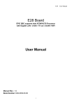
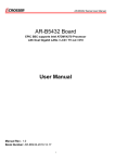
1.3 System Dissection
(1)
Dimensions
(2) Front Panel
Audio
COM
LAN 1~2
CF card bracket
USB 1~4
VGA
Power switch
Power LED
4
Antenna hole
Terminal block
Revision: 1.0
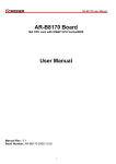
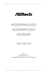
(3)System Configuration
1
2
7
8
3
9
4
10
11
5
12
6
13
5
Revision: 1.0
Item
Description
Quantity
1
LEFT COVER
1
2
PCI-104 CARD
1
3
DIN MOUNTING BRACKET
1
4
PCI-104 TAIL CONNECTOR
1
5
BASE
1
6
AR-B6050
1
7
HEAT COLUMN
1
8
POWER BOARD BRACKET
1
9
AR-PW0932TB
1
10 HEAT PLATE
1
11 SWITCH BUTTON
1
12 CF CARD BRACKET
1
13 BASE DDR DOOR
1
6
Revision: 1.0
2 Procedures of Assembly/Disassembly
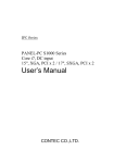
2.1 Installing the CF card
1. Unfasten two screws of CF bracket and then take out the CF card bracket.
Figure 1
2. Put the CF card into CF bracket (figure 2).
Please note that the direction of CF card and CF bracket (figure 3).
Figure 2
figure 3
7
Revision: 1.0
3. Push CF card to the bottom of bracket to stop the forwarding at the bend of bracket.
Figure 4
4. Push them into the CF slot of system machine and then fasten the two original screws to
fix CF bracket.
Figure 5
8
Revision: 1.0
2.2 Installing the Mini PCI-e interface card
1. Unfasten the six screws to take out the heat sink cover.
Figure 6
2. Maybe you need to force open the heat sink cover.
Figure 7
9
Revision: 1.0
3. Align the notch key on the Mini PCI-e card with rib on the slot.
Figure 8
4. Push Mini PCI-e card horizontally
.
Figure 9
10
Revision: 1.0
5. Using two M2 screws to fasten Mini PCI-e card.
Figure 10
6. Close the heat sink cover using the original screws to fasten heat sink cover and base.
(Please refer to figure 6)
11
Revision: 1.0
2.3 Installing the DDR2 SO-DIMM procedures
1. Unfasten the screw of the DDR cover and open the cover.
Figure 11
2. Align the notch key on DDR2 SO-DIMM with rib on the DDR2 socket.
Figure 12
12
Revision: 1.0
3. Push DDR2 SO-DIMM horizontally and make sure it is locked by hooks of two sides of
DDR2 socket.
Figure 13
4. Recover the DDR cover and fasten it with the screw.
.
13
Revision: 1.0
2.4 Assemble/Disassemble the DIN mounting bracket.
1. Hook the spring of the DIN mounting bracket onto the upper of DIN rail.
Figure 14
2. Press down the AR-ES6050FLD-W system machine and push it forward lightly.
STEP 1
STEP 2
Figure 15
14
Revision: 1.0
3. Make sure they are locked together.
Figure 16
4. Disassemble the DIN mounting bracket of AR-ES6050FLD-W system. Press down the
AR-ES6050FLD-W system machine and pull it back lightly.
STEP 1
STEP 2
Figure17
15
Revision: 1.0
Appendix. Cable Pin Define
1. Com cable
110mm
2. Power Cable
BLACK
BLACK
YELLOW
YELLOW
16
Revision: 1.0
3. Switch Cable
17
Revision: 1.0
3 AR-B6050 Board Guide
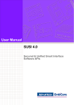
3.1 Block Diagram
18
Revision: 1.0
AR-B6050 Board Specifications
Intel Atom N450 1.66GHz
Intel Graphics Media Accelerator 950
1 x SO-DIMM supports DDRII up to 2GB(Memory DDR2 data transfer rates of 667
MT/s)
1 x VGA
4 x USB2.0
2 x SATA
1 x CF II
2 x RS-232
2 x GbE (Realtek RTL8111D)
1 x PCI-104 & 1 x Mini-PCIe
8-bit GPIO
19
Revision: 1.0
3.2 AR-B6050 H/W Information
This section describes the installation of AR-B6050. At first, it shows the Function
diagram and the layout of AR-B6050. It then describes the unpacking information
which you should read carefully, as well as the jumper/switch settings for the
AR-B6050 configuration.
3.2.1 AR-B6050 LAYOUT (Top side)
20
Revision: 1.0
JP1
COM1
VGA1
ATX1
COM2
J1
BAT1
SATA2
USB3
SYSFAN1
SATA1
USB1
CN2
CN4
USB2
CN3
JP3
LED1
JP2
LAN1
LVDS1
J7
LAN2
CN1
GPIO1
J6
3.2.2 AR-B6050 LAYOUT (Bottom side)
SODIMM1
CF
21
Revision: 1.0
3.3 Components and Jumps Setting List
1. JP1: LCD panel driving
voltage selection.
STATUS
1-2
2-3
SETTING
+3.3V
(Default).
+5V
4. SYSFAN1: System DC
Fan connector.
PIN
1
2
3
SETTING
GND
+12V
Fan speed data
7. JP2: Signal SERIRQ
connects to PCI-104 pin
#B1 selection.
STATUS
Open
Short
SETTING
Disconnected.
(Default)
Connected.
2. ATX1: AT power input
connector.
PIN
1
2
3
4
3. BAT1: CMOS battery holder.
SETTING
GND
GND
+12V
+12V
5. CN2: PCI-104 connector.
PCI-104 connector.
8. J7: COM1/2 SELECT RI OR
+12V
PIN SIGNAL
1
RI#1
3
+12V
5
RI#2
7
+12V
22
PIN
2
4
6
8
SIGNAL
RI#1_12V
RI#1_12V
RI#2_12V
RI#2_12V
CMOS battery holder.
6. CN3: MINI PCI-E connector.
MINI PCI-E connector.
9. GPIO1: GPIO connector.
PIN SETTING PIN SETTING
1
GPIO0
2
+5V
3
GPIO1
4
GPIO7
5
GPIO2
6
GPIO6
7
GPIO3
8
GPIO5
9
GND
10
GPIO4
Revision: 1.0
10. COM1: RS232 signal
connector for port #1.
PIN SETTING PIN SETTING
1
DCD #1
2
DSR #1
3
RX #1
4
RTS #1
5
TX #1
6
CTS #1
7
DTR #1
8
RI #1
9
GND
10
GND
13. SATA2: SATA device
connector #2.
11. COM2: RS232 signal
connector for port #2.
PIN SETTING PIN SETTING
1
DCD #2
2
DSR #2
3
RX #2
4
RTS #2
5
TX #2
6
CTS #2
7
DTR #2
8
RI #2
9
GND
10
GND
14. CN4: Audio signal
connector.
SATA device connector #2.
16. LAN1: RJ45 connector for
Gigabit Ethernet port #1.
RJ45 connector for Gigabit
Ethernet port #1. Audio line out
17. LAN2: RJ45 connector for
Gigabit Ethernet port #2.
RJ45 connector for
Gigabit Ethernet port #2.
12. SATA1: SATA device
connector #1.
SATA device connector
#1.
15. JP3: CF MASTER
SELECT
SET
SIGNAL
SHORT
MASTER
OPEN
SLAVE
18. J6: Front panel
connector.
STATUS
1-2
3-4
5-6
23
SETTING
Hardware reset
AT Mode - Short
ATX Mode - Open
Power Button
Revision: 1.0
19. VGA1: D-SUB-15 female
connector for VGA output.
D-SUB-15 female connector
for VGA output.
22. USB1: USB connector
Upper: Port #2.
Lower: Port #1.
SETTING
LCD VDD
NC
GND
NC
NC
NC
NC
GND
CLKData2+
I2C CLK
Data1Data0+
NC
LCD VDD
PIN
2
4
6
8
10
12
14
16
18
20
22
24
26
28
30
SHORT CMOS data clear
23. USB2: USB connector
Upper: Port #4.
Lower: Port #3.
25. LVDS1: LCD panel inverter
power connector.
PIN
1
3
5
7
9
11
13
15
17
19
21
23
25
27
29
20. J1: CMOS data clear
SETTING
GND
NC
NC
GND
NC
NC
NC
O CLK+
GND
Data2Data1+
I2C Data
Data0NC
LCD VDD
26. CN1: LCD panel inverter
power connector.
PIN
1
2
3
4
5
6
24
SETTING
+12V
+12V
GND
BKL ON
GND
Reserved.
21. USB3: Internal USB2.0
connector
PIN SETTING PIN SETTING
1
+5V
2
+5V
3
USB54
USB65
USB5+
6
USB6+
7
GND
8
GND
9
GND
10
GND
24. LED1: System power and
HDD access indicators.
Green: System power
indicator.
Yellow: HDD access
indicator.
Revision: 1.0
27. DIMM1: DDR-II SODIMM
Socket.
DDR-II SODIMM
Socket.
28. CF1: Type-II compact flash
card socket.
+3.3V CF card only and
UDMA mode supported.
25
Revision: 1.0
3.4 BIOS Setting
The BIOS Setup Utility is a hardware configuration program built into your computer’s BIOS.
To activate the BIOS Utility, press F2 during POST (when “Press <F2> to enter Setup”
message is prompted on the bottom of screen). Press <F12> during POST to enter
multi-boot menu. In this menu, user can change boot device without entering BIOS SETUP
Utility.
This chapter describes the BIOS menu displays and explains how to perform common
tasks needed to get the system up and running. It also gives detailed explanation of the
elements found in each of the BIOS menu. The following topics are covered:
Main Setup
Advanced Setup
Security Setup
Boot Setup
Exit Setup
26
Revision: 1.0
3.4.1 Main Setup
Once you enter the InsydeH2O BIOS™ Setup Utility, the Main Menu will appear on the
screen. Use the arrow keys to highlight the item and then use the <F5> <F6> keys to select
the desired value in each item.
Note: The control keys are listed at the bottom of the menu. If you need any help with the item fields,
you can press the <F1> key, and the relevant information will be displayed.
Item
System Date
System Time
Option
Description
Set the system date. Note that the ‘Day’
Format : MM/DD/YYYY
automatically changes when you set the
(month/day/year)
date.
Format: HH:MM:SS
Set the system time.
(hour:minute:second)
Processor
Type
N/A
This field shows the CPU type and speed
of the system.
System Bus
Speed
N/A
This field displays the bus speed of the
system.
System
Memory
Speed
N/A
This field displays the real speed of the
memory.
27
Revision: 1.0
Cache RAM
N/A
This field displays the cache ram of the
CPU.
Total Memory
N/A
Displays the total memory available.
SODIMM 0
N/A
This field displays the memory of the
SODIMM0.
BIOS Revision
N/A
Displays system BIOS version.
28
Revision: 1.0
3.4.2 Advanced Chipset Setup
Note: The control keys are listed at the bottom of the menu. If you need any help with the item fields,
you can press the <F1> key, and the relevant information will be displayed.
Item
Peripheral
Configuration
IDE
Configuration
Video
Configuration
Hardware
Monitor
Option
Serial Port A
Serial Port B
Azalia Audio control
IDE Controller
HDC Configure as
Init Display First
IGD-Device2, Function1
IGD-Frame Buffer Size
IGD-DVMT Size
IGD-Boot Type
IGD-LCD Panel type
Description
Enter the Peripheral Configuration
menu.
Enter the IDE Configuration menu.
Enter the Video Configuration menu.
This field displays the Hardware
Monitor of the system.
N/A
29
Revision: 1.0
3.4.3 Security Setup
Note: The control keys are listed at the bottom of the menu. If you need any help with the item fields,
you can press the <F1> key, and the relevant information will be displayed.
Item
Supervisor
Password
Option
Not Installed
Installed
Set
Supervisor
Password
N/A
Description
Shows the setting of the Supervisor
password
Press Enter to set the user password. When
user
password is set, this password protects the
BIOS Setup
Utility from unauthorized access. The user
can enter
Setup menu only and does not have right to
change the
value of parameters.
30
Revision: 1.0
Setting a Password
Follow these steps as you set the user or the supervisor password:
1. Use the ↑ and ↓ keys to highlight the Set Supervisor Password parameter and press the
Enter key. The Set Supervisor Password box appears:
2. Type a password in the “Enter New Password” field. The password length can not exceed 8
alphanumeric characters (A-Z, a-z, 0-9, not case sensitive). Retype the password in the
“Confirm New Password” field.
IMPORTANT: Be very careful when typing your password because the characters do not
appear on the screen.
3. Press Enter. After setting the password, the computer sets the User Password parameter to
“Set”.
4. If desired, you can opt to enable the Password on boot parameter.
5. When you are done, press F10 to save the changes and exit the BIOS Setup Utility.
Removing a Password
Follow these steps:
1. Use the ↑ and ↓ keys to highlight the Set Supervisor Password parameter and press the
Enter key. The Set Password box appears:
2. Type the current password in the Enter Current Password field and press Enter.
3. Press Enter twice without typing anything in the Enter New Password and Confirm New
Password fields. The computer then sets the Supervisor Password parameter to “Clear”.
4. When you have changed the settings, press u to save the changes and exit the BIOS Setup
Utility.
31
Revision: 1.0
3.4.4 Boot Setup
Note: The control keys are listed at the bottom of the menu. If you need any help with the item fields,
you can press the <F1> key, and the relevant information will be displayed.
Item
Option
Description
Select Boot Devices to select specific
devices to support boot.
(The item can't display when no device.)
Boot Device
Priority
N/A
Hard disk
Drive
N/A
Show the Hard disk drives.
(The item can't display when no device.)
CD/DVD-ROM
Drive
N/A
Show the CD/DVD-ROM drives.
(The item can't display when no device.)
USB Drive
N/A
Show the USB diskette drives.
(The item can't display when no device.)
Other
N/A
Show the other drives.
(The item can't display when no device.)
PXE Boot to
LAN
Enabled
Disabled
Disables or enables PXE boot to LAN.
32
Revision: 1.0
3.4.5 Exit Setup
Note: The control keys are listed at the bottom of the menu. If you need any help with the item fields,
you can press the <F1> key, and the relevant information will be displayed.
Item
Exit Saving
changes
Save change
without Exit
Option
Yes
NO
Yes
NO
Description
Exit
Discarding
changes
Yes
NO
Exit system setup and without saving your
changes.
Load Optimal
Defaults
Yes
NO
Load default values for all SETUP item.
Discarding
changes
Yes
NO
Load previous values from CMOS for all
SETUP items.
Exit System Setup and save your changes.
Save Your changes and without exiting
system.
33
Revision: 1.0
3.5 WATCHDOG, GPIO, AND BYPASS PROGRAMMING
3.5.1 Watchdog Programming
This section describes the usage of WATCHDOG. AR-B6050 integrated the
WATCHDOG that enable user to reset the system after a time-out event. User can use a
program to enable the WATCHDOG and program the timer in range of 1~255
second(s)/minute(s). Once user enables the WATCHDOG, the timer will start to count down
to zero except trigger the timer by user’s program continuously. After zeroize the timer (stop
triggering), the WATCHDOG will generate a signal to reset the system. It can be used to
prevent system crash or hang up. The WATCHDOG is disabled after reset and should be
enabled by user’s program.
Please refer to the following table to program WATCHDOG properly, and user could test
WATCHDOG under ‘Debug’ program.
C:>debug
-o 2E 87
-o 2E 01
-o 2E 55
-o 2E 55
-o 2E 07
-o 2F 07
-o 2E 72
-o 2F 40
-o 2E 72
-i 2F
-o 2F xx
-o 2E 73
-o 2F ##
-q
Address port: 2E and Data port: 2F
To enter debug mode.
To enter configuration.
To point to Logical Device Number Reg.
To select logical device 7 (WATCHDOG).
To select “keyboard reset” as WATCHDOG output to reset system.
Preparing to select the unit of timer equals minute or second.
To read the value of index “2F”.
The value “xx” equals [(value of index “2F”) OR (80)].
OR (80): unit is second.
OR (00): unit is minute.
Preparing to set the WATCHDOG timer value.
The value “##” ranges between 01 ~ FF (1 ~ 255 seconds).
00: To disable WATCHDOG.
To quit debug mode
Notice: The “actual” timer value may not match with the “theoretical”. That is
because of the tolerance of internal oscillating clock and cannot be adjusted or
optimized.
The WATCHDOG sample code of C language as below:
//====================================================================
=======
// Rev Date
Name Description
//====================================================================
=======
// 1.0
12/16/2009 Willy
W83627EHF WatchDog timer test
//====================================================================
34
Revision: 1.0
=======
//====================================================================
=======
// Language include files
//====================================================================
=======
#include <conio.h>
#include <stdlib.h>
#include <stdio.h>
#include <dos.h>
//====================================================================
=======
// Normal procedure
//====================================================================
=======
void Show_Help();
//====================================================================
=======
// Main procedure
//====================================================================
=======
int main(int argc, char *argv[])
{
unsigned char IO_Port_Address=0x2E;
unsigned char Time;
unsigned char Temp;
if ( argc != 2 )
{ Show_Help();
return 1;
}
clrscr();
Time=atoi(argv[1]);
// Set Watchdog
outportb(IO_Port_Address,0x87);
outportb(IO_Port_Address,0x87);
// (EFER) Extended Functions Enable Register
outportb(IO_Port_Address,0x2D);
// Point to Global Reg.
// Select Multi-Function pin, (Bit0=0 Watchdog Function)
outportb(IO_Port_Address+1,(inportb(IO_Port_Address+1)&0xFE));
outportb(IO_Port_Address,0x07);
// Point to Logical Device Number Reg.
outportb(IO_Port_Address+1,0x08); // Select logical device 8, (Watchdog Function)
outportb(IO_Port_Address,0x30);
// Device Active register
outportb(IO_Port_Address+1,0x01);
35
Revision: 1.0
outportb(IO_Port_Address,0xF5);
// Select Watchdog count mode seconds or
minutes
outportb(IO_Port_Address+1,0x02);
// Default is second and KBRST mode.
outportb(IO_Port_Address,0xF6);
// Set Watchdog Timer Value
outportb(IO_Port_Address+1,Time); // 0x00 to disable, max 0xFF
textcolor(YELLOW);
for(Temp=Time;Temp>0;Temp--)
{
outportb(IO_Port_Address,0xF6); // Read Watchdog Timer Value
Time=inportb(IO_Port_Address+1);
gotoxy(20,10);
cprintf(">>> After %3d Second will reset the system. <<<",Time);
delay(1000);
}
textcolor(LIGHTRED);
gotoxy(18,10);
cprintf("If you can see this message, Reset system is Fail");
return 1;
}
//====================================================================
=======
// Function : Show_Help()
// Input : // Change
:// Return : // Description : Show Help string.
//====================================================================
=======
void Show_Help()
{
clrscr();
printf("WatchDog Test for W83627EHF\n\n");
printf("Sample:
\n");
printf("
WDT.EXE 10
\n");
printf("( For 10 seconds to reset. )\n");
}
//====================================================================
=======
36
Revision: 1.0
3.5.2 GPIO Programming
This section describes the usage of GPIOs. AR-B6050 integrated eight bits, 5V TTL
level, bidirectional, and software programmable GPIOs for user’s application. They are all
capable of 5 mA source current for output and 8 mA sink current for input individually. The
electrical characteristics of GPIOs as following table:
PIN SIGNAL PIN SIGNAL
1
GPO0
2
VCC
3
GPO7
4
GPI7
5
GPO2
6
GPI6
7
GPO3
8
GPI5
9
GND
10
GPI4
The GPIO sample code of C language as below:
//====================================================================
=======
// Rev Date
Name Description
//====================================================================
=======
// 1.0
03/17/10 Willy
GPIO10~GPIO17 Test utility for W83627EHF.
//====================================================================
=======
//====================================================================
=======
// Turbo C++ Version 3.0 Copyright(c) 1990, 1992 by Borland International,Inc.
//====================================================================
=======
//====================================================================
=======
// Language include files
//====================================================================
=======
#include <conio.h>
#include <stdio.h>
//====================================================================
=======
// Normal procedure
//====================================================================
=======
void Show_Help();
void Show_Fail();
void Show_Pass();
37
Revision: 1.0
//====================================================================
=======
// Main procedure
//====================================================================
=======
int main(int argc)
{
char *Model_Name="AR-B6050";
char *Version="v1.0";
unsigned char IO_PORT_BASE=0x2E; // DATA_PORT = IO_PORT_BASE + 1;
unsigned char data;
int result=0;
if ( argc > 1 )
{ Show_Help();
return 1; }
clrscr();
textcolor(WHITE);
gotoxy(1, 1);
cprintf("<>=============================================================
=============<>");
gotoxy(1, 2); cprintf("|| W83627EHF GPIO Test Utility %s Acrosser Technology Co., Ltd.
||",Version);
gotoxy(1, 3);
cprintf("<>=============================================================
=============<>");
gotoxy(1, 4);
cprintf("<>=============================================================
=============<>");
gotoxy(1, 5); cprintf("|| Model Name :
||");
gotoxy(1, 6); cprintf("|| SIO IO Base :
||");
gotoxy(1, 7);
cprintf("<>=============================================================
=============<>");
// Show Got Parameter Informat
textcolor(LIGHTGRAY);
gotoxy(18,5);
cprintf("%s",Model_Name);
gotoxy(18,6);
cprintf("%X",IO_PORT_BASE);
// Enter W83627EHF Config
outportb(IO_PORT_BASE,0x87);
outportb(IO_PORT_BASE,0x87);
// Set Multi-function Pins to GPIO
outportb(IO_PORT_BASE,0x29);
outportb(IO_PORT_BASE+1,(inportb(IO_PORT_BASE+1) | 0x01));
// Select GPIO Port device
38
Revision: 1.0
outportb(IO_PORT_BASE,0x07);
outportb(IO_PORT_BASE+1,0x07);
// Set GPIO Port Active
outportb(IO_PORT_BASE,0x30);
outportb(IO_PORT_BASE+1,0x01);
// Set GPIO I/O Register to 00h
outportb(IO_PORT_BASE,0xF3);
outportb(IO_PORT_BASE+1,0x00);
// Set W83627EHF GPIO10~13 to Output, GPIO14~GPIO17 to Input
outportb(IO_PORT_BASE,0xF0);
outportb(IO_PORT_BASE+1,0xF0);
// Set W83627EHF GPIO10~13 to High
outportb(IO_PORT_BASE,0xF1);
outportb(IO_PORT_BASE+1,0x0F);
// Read W83627EHF GPIO14~17 Status, if not High error.
data=inportb(IO_PORT_BASE+1)&0xF0;
if(data!=0xF0)
result=1;
// Set W83627EHF GPIO10~13 to Low
outportb(IO_PORT_BASE,0xF1);
outportb(IO_PORT_BASE+1,0x00);
// Read W83627EHF GPIO14~17 Status, if not Low error.
data=inportb(IO_PORT_BASE+1)&0xF0;
if(data!=0x00)
result=1;
// Set W83627EHF GPIO10~13 to input, GPIO14~GPIO17 to Output
outportb(IO_PORT_BASE,0xF0);
outportb(IO_PORT_BASE+1,0x0F);
// Set W83627EHF GPIO14~17 to High
outportb(IO_PORT_BASE,0xF1);
outportb(IO_PORT_BASE+1,0xF0);
// Read W83627EHF GPIO10~13 Status, if not High error.
data=inportb(IO_PORT_BASE+1)&0x0F;
if(data!=0x0F)
result=1;
// Set W83627EHF GPIO14~17 to Low
outportb(IO_PORT_BASE,0xF1);
outportb(IO_PORT_BASE+1,0x00);
// Read W83627EHF GPIO14~17 Status, if not Low error.
data=inportb(IO_PORT_BASE+1)&0x0F;
if(data!=0x00)
result=1;
// Exit W83627EHF Config
outportb(IO_PORT_BASE,0xAA);
39
Revision: 1.0
if(result)
Show_Fail();
else
Show_Pass();
return result;
}
//====================================================================
=======
// Function : Show_Help()
// Input : // Change
:// Return : // Description : Show Title string.
//====================================================================
=======
void Show_Help()
{
clrscr();
printf("GPIO Test utility for W83627EHF\n\n");
Vcc\n");
printf("GPIO0 迋迋迋芼
printf("GPIO1 迋迋迋銀迋迋 GPIO7\n");
printf("GPIO2 迋迋芼 迋迋 GPIO6\n");
printf("GPIO3 迋迋銀迋迋迋 GPIO5\n");
printf("GND 迋迋迋 GPIO4\n");
}
//====================================================================
=======
// Function : Show_Fail()
// Input : // Change
:// Return : // Description : Show Fail Message.
//====================================================================
=======
void Show_Fail()
{
textcolor(LIGHTRED);
gotoxy(20,10);
cprintf(" 詗詗詗詗 詗詗詗
詗詗
詗
");
gotoxy(20,11);
cprintf(" 詗
詗 詗
詗
詗
");
gotoxy(20,12);
cprintf(" 詗詗詗
詗詗詗詗
詗
詗
");
gotoxy(20,13);
cprintf(" 詗
詗
詗
詗
詗
");
gotoxy(20,14);
cprintf(" 詗
詗
詗
詗詗
詗詗詗詗");
}
//====================================================================
=======
40
Revision: 1.0
// Function : Show_Pass()
// Input : // Change
:// Return : // Description : Show Pass Message.
//====================================================================
=======
void Show_Pass()
{
textcolor(LIGHTGREEN);
gotoxy(20,10);
cprintf(" 詗詗詗詗 詗詗詗 詗詗詗詗 詗詗詗詗");
gotoxy(20,11);
cprintf(" 詗
詗 詗 詗 詗
詗
");
gotoxy(20,12);
cprintf(" 詗詗詗詗 詗詗詗詗 詗詗詗詗 詗詗詗詗");
gotoxy(20,13);
cprintf(" 詗
詗
詗
詗
詗");
gotoxy(20,14);
cprintf(" 詗
詗
詗 詗詗詗詗 詗詗詗詗");
}
//====================================================================
=======
41
Revision: 1.0
3.6 GPIO and Watchdog
3.6.1 Overview
This model provides both a GPIO interface and a Watchdog timer. Users can use the
GPIO and Watchdog APIs to configure and to access the GPIO interface and the Watchdog
timer. The GPIO has eight ports. Each port can be configured as an input port or an output
port. The Watchdog timer can be set to 1~255 seconds. Setting the timer to zero disables
the timer. The remaining seconds of the timer to reboot can be read from the timer.
3.6.2 File Description
1. AcroIO.h
This header file includes API declarations and macros for GPIO and Watchdog.
2. AcroIO.lib, AcroIO.dll
The libraries which provide access to GPIO and Watchdog functions.
42
Revision: 1.0
3.7 API List and Descriptions
3.7.1 GPIO
1.
Syntax:
Status_t getGpioCapability(uint32_t *pInputs, uint32_t *pOutput )
Description: This function shows the capability of each GPIO port that it is an output
port or an input port.
Parameters:
The returned value which is put at *pInput indicates whether the corresponding GPIO
ports are input ports or not. For example, say, the value at *pInput is 0x00000005, it
indicates that the ports GPIO0 and GPIO2 are both input ports.
The returned value which is put at *pOutput indicates whether the corresponding GPIO
ports are output ports or not. For example, say, the value at *pOutput is 0x000000FA, it
indicates that the ports GPIO7, GPIO6, GPIO5, GPIO4, GPIO3, GPIO1 are all output
ports. If the *pInput shows that a certain GPIO port is an input port and the *pOutput
shows that this port is an output port, this means this port can be configured as an input
port or an output port by invoking the ‘setGpioDirection( )’. If a certain GPIO port is
neither an input port nor an output port, this model does not enable this GPIO port.
Return Value: If the function gets the value successfully, it returns STATUS_SUCCESS,
any other returned value stands for error.
2. Syntax:
Status_t getGpioDirection( uint32_t Id, uint32_t *pDirection )
Description: Get the current state of GPIO input/output configuration.
Parameters:
The argument ‘Id’ has two formats of parameters. If ‘Id’ is ‘GPIO_ALL’, the returned
value at *pDirection shows the state of every GPIO port. A bit ‘1’ at the value of
*pDirection stands for an input port. A bit ‘0’ at the value of *pDirection stands for an
output port. For example, say, the *pDirection is 0x00000085, this indicates that the
ports GPIO7, GPIO2, GPIO0 are input ports. Other GPIO ports (if enabled) are output
ports. The other format of the argument ‘Id’ is that the ‘Id’ is ‘GPIO_ID0’ ~ ‘GPIO_ID32’.
For example, say, ‘Id’ is GPIO_ID2, the returned value of *pDirection is 0x1(input port)
or 0x0(output port).
Code Sample:
Case 1:
Status_t status;
uint32_t Direction;
status = getGpioDirection(GPIO_ALL, &Direction);
Case 2:
Status_t status;
43
Revision: 1.0
uint32_t Direction;
status = getGpioDirection(GPIO_ID2, &Direction);
if(Direction == 0x1) {
cout << “GPIO2 is an Input port” << endl;
} else {
cout << “GPIO2 is an Output port” << endl;
}
Return Value: If the function gets the values successfully, it returns STATUS_SUCCESS,
any other returned value stands for error.
3. Syntax:
Status_t setGpioDirection( uint32_t Id, uint32_t Direction )
Description: Set the current state of GPIO input/output configuration.
Parameters:
The argument ‘Id’ has two formats of parameters. If ‘Id’ is ‘GPIO_ALL’, the parameter
‘Direction’ is bit patterns to set the input/output configuration of the corresponding GPIO
ports. A bit ‘1’ at the value of ‘Direction’ sets the corresponding GPIO port as an input
port. A bit ‘0’ at the value of ‘Direction’ sets the corresponding GPIO port as an output
port. The other format of the argument ‘Id’ is that the ‘Id’ is ‘GPIO_ID0’ ~ ‘GPIO_ID32’.
For example, say, ‘Id’ is GPIO_ID2. If ‘Direction’ is any value other than 0, it configures
the port GPIO2 as an input port. If ‘Direction’ is 0, it configures the port GPIO2 as an
output port.
Return Value: If the function sets the values successfully, it returns
STATUS_SUCCESS, any other returned value stands for error.
4. Syntax:
Status_t getGpioLevel( uint32_t Id, uint32_t *pLevel )
Description: Get the current state of the GPIO ports.
Parameters:
The argument ‘Id’ has two formats of parameters. If ‘Id’ is ‘GPIO_ALL’, the returned
value at *pLevel shows the state of every GPIO port. A bit ‘1’ at the value of *pLevel
stands for a logical high. A bit ‘0’ at the value of *pLevel stands for a logical low. For
example, say, the *pLevel is 0x00000085, this indicates that the ports GPIO7, GPIO2,
GPIO0 are at the state of logical high. Other GPIO ports (if enabled) are at the state of
logical low. The other format of the argument ‘Id’ is that the ‘Id’ is ‘GPIO_ID0’ ~
‘GPIO_ID32’. For example, say, ‘Id’ is GPIO_ID2, the returned value of *pLevel is
0x1(logical high) or 0x0(logical low).
Return Value: If the function gets the values successfully, it returns
STATUS_SUCCESS, any other returned value stands for error.
5. Syntax:
44
Revision: 1.0
Status_t setGpioLevel( uint32_t Id, uint32_t Level )
Description: Set the current state of GPIO ports.
Parameters:
The argument ‘Id’ has two formats of parameters. If ‘Id’ is ‘GPIO_ALL’, the parameter
‘Level’ is bit patterns to be set to the corresponding GPIO ports. A bit ‘1’ at the value of
‘Level’ sets the corresponding GPIO port to logical high. A bit ‘0’ at the value of ‘Level’
sets the corresponding GPIO port to logical low. The setting to an input port is ignored.
The other format of the argument ‘Id’ is that the ‘Id’ is ‘GPIO_ID0’ ~ ‘GPIO_ID32’. For
example, say, ‘Id’ is GPIO_ID2. If ‘Level’ is any value other than 0, it sets the port
GPIO2 to logical high. If ‘Level’ is 0, it sets the port GPIO2 to logical low.
Return Value: If the function sets the values successfully, it returns
STATUS_SUCCESS, any other returned value stands for error.
3.7.2 Watchdog
1. Syntax:
Status_t getWtdTimer(uint32_t *pTimer)
Description: This function read the value of the watchdog timer.
Parameters: The value of the timer is put at the memory which is pointed by the
argument ‘pTimer’.
Return Value: This function always returns STATUS_SUCCESS.
2. Syntax:
Status_t setWtdTimer( uint32_t Timer )
Description: This function sets the watchdog timer register to the value ‘Timer’ and
starts to count down. The value could be 0 ~ 255. The unit is second. Setting the timer
register to 0 disables the watchdog function and stops the countdown.
Parameters: The parameter ‘Timer’ is the value to be set to watchdog timer register. The
range is 0 ~ 255.
Return Value: This function always returns STATUS_SUCCESS.
45