1
Copyright © 2001 International Business Machines Corp.
Eclipse Corner Article
ARM Cross Development with Eclipse
Summary
Eclipse with the CDT plug-in makes a great embedded software
development platform for the ARM microcomputer family. This tutorial
guides the reader through the myriad of web sites, software
downloads and setups required constructing a complete ARM
Integrated Development Environment (IDE) We design a simple
“blinker” program and debug and execute the program on a target
ARM microprocessor board. The software is free and the hardware
required to get started is less than $100.
By James P. Lynch, Control Techniques
March 1, 2006
Introduction
I credit my interest in science and electronics to science fiction movies in the fifties.
Robbie the Robot in the movie “Forbidden Planet” especially enthralled me and I
watched every episode of Rocky Jones, Space Ranger on television. In high school, I
built a robot and even received a ham radio operator license at age 13.
Electronic kits were popular then and I built many Heath kits and Knight kits,
everything from ham radio gear to televisions, personal computers and robots. These
kits not only saved money at the time, but the extensive instruction manuals taught the
basics of electronics.
Unfortunately, surface mount technology and pick-and-place machines obliterated any
cost advantage to “building it yourself” and Heath and Allied Radio all dropped out of
the kit business.
What of our children today? They have home computers to play with, don’t they? Do
you learn anything by playing a Star Wars game or downloading music? I think not,
while these pastimes may be fun they are certainly not intellectually creative.
A couple years ago, there were 5 billion microcomputer chips manufactured planetwide. Only 300 million of these went into desktop computers. The rest went into
toasters, cars, fighter jets and Roomba vacuum cleaners. This is where the real action
is in the field of computer science and engineering. It’s called “embedded software
development”.
Can today’s young student or home hobbyist tired of watching Reality Television
dabble in microcomputer electronics? The answer is an unequivocal YES!
Most people start out with projects involving the Microchip PIC series of
microcontrollers. You may have seen these in Nuts and Volts magazine or visited the
plethora of web sites devoted to PIC computing. PIC microcomputer chips are very
cheap (a couple of dollars) and you can get an IDE (Integrated Development
Environment), compilers and emulators from Microchip and others for a very
reasonable price.
Another inexpensive microcontroller for the hobbyist to work with is the Rabbit
microcomputer. The Rabbit line is an 8-bit microcontroller with development packages
(board and software) costing less that $140.
I’ve longed for a real, state-of-the-art microcomputer to play with. One that can do 32bit arithmetic as fast as a speeding bullet and has all the on-board RAM and EPROM
needed to build sophisticated applications. My prayers have been answered recently
as big players such as Texas Instruments, Philips and Atmel have been selling
inexpensive microcontroller chips based on the 32-bit ARM architecture. These chips
have integrated RAM and FLASH memory, a rich set of peripherals such as serial I/O,
PWM, I2C, SSI, Timers etc. and high performance at low power consumption.
A very good example from this group is the Philips LPC2000 family of microcontrollers.
The LPC2106 has the following features, all enclosed in a 48-pin package costing
about $11.88 (latest price from Digikey for one LPC2106).
Key features
16/32-bit ARM7TDMI-S processor.
64 kB on-chip Static RAM.
128 kB on-chip Flash Program Memory. In-System Programming (ISP) and InApplication Programming (IAP) via on-chip boot-loader software.
Vectored Interrupt Controller with configurable priorities and vector addresses.
JTAG interface enables breakpoints and watch points.
Multiple serial interfaces including two UARTs (16C550), Fast I²C (400 kbits/s)
and SPI™.
Two 32-bit timers (7 capture/compare channels), PWM unit (6 outputs), Real
Time Clock and Watchdog.
Up to thirty-two 5 V tolerant general-purpose I/O pins in a tiny LQFP48 (7 x 7
mm2) package.
60 MHz maximum CPU clock available from programmable on-chip PhaseLocked Loop with settling time of 100 us.
On-chip crystal oscillator with an operating range of 1 MHz to 30 MHz.
Two low power modes: Idle and Power-down.
Processor wake-up from Power-down mode via external interrupt.
Individual enable/disable of peripheral functions for power optimization.
Dual power supply:
o CPU operating voltage range of 1.65 V to 1.95 V (1.8 V +- 8.3 pct.).
o I/O power supply range of 3.0 V to 3.6 V (3.3 V +- 10 pct.) with 5 V
tolerant I/O pads.
Several companies have come forward with the LPC2000 microcontroller chips placed
on modern surface-mount boards, ready to use.
Olimex, an up-and-coming electronics company in Bulgaria, offers a family of Philips
LPC2100 boards. Specifically they offer three versions with the LPC2106 CPU. The
Olimex web site is www.olimex.com. You can also buy these from Spark Fun
Electronics in Colorado; their web site is www.sparkfun.com The Olimex boards are
also carried by Microcontroller Pros in California, their web site is
www.microcontrollershop.com
The New Micros TiniARM and Plug-an-ARM family distinguish themselves in their
small size so that you may solder them directly into your applications. They sell a
development board to help you get started. New Micros product may be purchased
online from their website www.newmicros.com.
Embedded Artists products can be purchased from their online store at :
http://www.embeddedartists.com/ and in the USA from : http://www.lpctools.com/
This is the Olimex LPC-H2106 header board. You
can literally solder this tiny board onto Radio Shack
perfboard, attach a power supply and serial cable
and start programming. It costs about $49.95
Obviously, it requires some soldering to get started.
This is the Olimex LPC-P2106 prototype
board. Everything is done for you. There’s a
power connector for a wall-wart power supply,
a DB-9 serial connector and a JTAG port. It
costs about $59.95 plus $2.95 for the wallwart power supply.
This is the Olimex LPT-MT development
board; it has everything the prototype board
above includes plus a LCD display and four
pushbuttons to experiment with. It costs
about $79.95 plus $2.95 for the wall-wart
power supply.
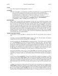
This is the New Micros Tini2106 TiniARM board.
The ten plated-through holes are for a JTAG
debugger. Being the size of a large postage stamp,
the TiniARM is limited in the number of IO ports and
peripherals that can be brought out on the 24-pin double row header on the bottom.
The TiniARM costs $69.00 and at 1” x 1.3” it is certainly the smallest of the available
ARM “Stamp” boards.
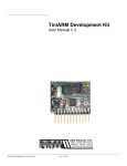
To simplify development
of TiniARM applications,
New Micros sells this
Tini2106 Development
Kit for $95. The Tini2106
board mentioned above
is included in this price.
The development board
includes a voltage
regulator, DB-9 serial
connector for flash
programming and a
reset button. There’s a
large prototype area for you to add your own circuits.
You will have to fashion an adapter to fit a standard 20-pin JTAG cable into the
TiniARM’s 10-pin JTAG header (see Appendix for information on how to do this)
Embedded Artists sell this LPC2106-based header board for $51. It includes a 32
Kbyte serial EPROM and all I/O ports are brought out to the header pins.
This $39 prototype board from Embedded Artists accepts the LPC2106 header board
above and provides a JTAG connector, voltage regulators, Flash Programming serial
port, 4 switches and 16 LEDs.
The point in showing these products is that they all provide a complete LPC2106
hardware development platform for under $100. For no particular reason other that
being the lowest cost, we will concentrate on the Olimex LPC-P2106 board for this
tutorial. However, an Appendix will show how easy it is to use the same software on
the New Micros TiniARM family of boards.
For starting out, I would recommend the LPC-P2106 prototype board since it has an
open prototype area for adding I2C chips and the like for advanced experimentation.
When you do design and develop something really clever, you could use the LPCH2106 header board (or the TiniARM or Embedded Artists header boards) soldered
into a nice Jameco or Digikey prototype board and know that the CPU end of your
project will work straight away. If you need to build multiple copies of your design,
Spark Fun can get small runs of blank circuit boards built for $5.00 per square inch.
You can acquire the Eagle-Lite software from CadSoft for free to design the schematic
and PCB masks.
So the hardware to experiment with 32-bit ARM microprocessors is available and
affordable. What about the software required for editing, compiling, linking and
downloading applications for the LPC2106 board?
Embedded microcomputer development software has always been considered
“professional” and priced accordingly. It’s very common for an engineer in a technical
company to spend $1000 to $5000 for a professional development package. I once
ordered $18,000 of compilers and emulators for a single project. In the professional
engineering world, time is money. The commercial software development packages for
the ARM architecture install easily, are well supported and rarely have bugs. In fact,
most of them can load your program into either RAM or FLASH and you can set
breakpoints in either. The professional compiler packages are also quite efficient; they
generate compact and speedy code.
The Rowley CrossWorks recommended by Olimex is $904.00, clearly out of the range
for the student or hobby experimenter. I’ve seen other packages going up as high as
$3000. A professional would not bat an eyelash about paying this – time is money.
There is a low cost alternative to the high priced professional software development
packages, the GNU toolset. GNU is the cornerstone of the open-source software
movement. It was used to build the LINUX operating system. The GNU Toolset
includes compilers, linkers, utilities for all the major microprocessor platforms, including
the ARM architecture. The GNU toolset is free.
The editor of choice these days is the Eclipse open-source Integrated Development
Environment (IDE). By adding the CDT plug-in (C/C++ Development Toolkit), you can
edit and build C programs using the GNU compiler toolkit. Eclipse is also free.
Philips provides a Windows flash programming utility that allows you to transfer the
hex file created by the GNU compiler/linker into the onboard flash EPROM on the
LPC2106 microprocessor chip. The Philips tool is also free.
Dominic Rath has made available a free Windows utility called OpenOCD that allows
the Eclipse/GDB (GNU Debugger) to access the Philips LPC2106 microprocessor via
the JTAG port using an expensive device called the “wiggler”. The Norwegian
company Zylin has created a custom version of CDT that enables the debugger to
work better with cross-development applications.
At this point, you’re probably saying “this is great – all these tools and they’re FREE!”
In the interest of honesty and openness, let’s delineate the downside of the free open
software GNU tools.
You need an internet broadband connection to download these tools.
Installation of these software tools is tedious and time-consuming.
There’s no telephone support.
If you were a professional programmer, you might not accept these limitations. For the
student or hobbyist, the Eclipse/GNU toolset still gives fantastic capabilities for zero
cost.
The Eclipse/GNU Compiler toolset we will be creating in this tutorial operates in three
modes.
A. Application programmed into FLASH (no debugging)
You can use a standard 9pin PC serial cable to
connect COM1 to the
Olimex board.
COM1
DB-9
Serial Port
Short the BSL jumper to
download and program
into flash.
Remove the BSL
jumper to execute
application
In this mode, the Eclipse/GNU development system assembles, compiles and links
your application for loading into FLASH memory. The output of the compiler/linker suite
is an Intel hex file, e.g. main.hex.
The Philips LPC2000 Flash Utility is started within Eclipse and will download your
hex file and program the flash memory through the standard COM1 serial cable. The
Boot Strap Loader (BSL) jumper must be shorted (installed) to run the Philips flash
programming utility.
To execute the application, you remove the BSL jumper and push the RESET button to
start the application. Assuming you are a zero-defect programmer, your application will
run.
B. Application programmed and debugged into FLASH
Olimex ARM JTAG Adapter
( WIGGLER )
LPT1
Install the Debug JT
jumper while debug
FLASH
COM1
The BSL jumper is removed
In this mode, the Eclipse/GNU development system assembles, compiles and links
your application for loading into FLASH memory. The output of the compiler/linker suite
is a GNU output file, e.g. main.hex and/or main.out.
The Philips LPC2000 Flash Utility is started within Eclipse and will download your
hex file and program the flash memory through the standard COM1 serial cable. The
Boot Strap Loader (BSL) jumper must be shorted (installed) to run the Philips flash
programming utility.
The PC is connected from the PC’s printer port LPT1 to the JTAG port through the
Olimex ARM JTAG interface (costs about $19.95 from Spark Fun Electronics). The
Olimex ARM JTAG is a clone of the Macraigor Wiggler.
You can then run the OpenOCD program as an external tool from within Eclipse. The
CDT debugger (started from within Eclipse) communicates with the OpenOCD
program that operates the JTAG port using the Wiggler. From this point on, using the
debugging information in the main.out file, you can set up to two hardware
breakpoints, view variables and structures and, of course, run the application.
Now you can debug to your heart’s content; as long as you don’t specify more than two
breakpoints.
C.
Application programmed and debugged into RAM
Olimex ARM JTAG Adapter
( WIGGLER )
LPT1
The BSL jumper
generally doesn’t matter
while using JTAG
In this mode, the Eclipse/GNU development system assembles, compiles and links
your application for loading into RAM memory. The output of the compiler/linker suite is
a GNU main.out file.
The PC is connected from the PC’s printer port LPT1 to the JTAG port through the
Olimex ARM JTAG interface (costs about $19.95 from Spark Fun Electronics). The
Olimex ARM JTAG is a clone of the Macraigor Wiggler.
You can run the OpenOCD program as an external tool from within Eclipse. The CDT
debugger (started from within Eclipse) communicates with the OpenOCD program that
operates the JTAG port using the Wiggler. With the CDT debugger, you can connect
to the Wiggler and load the GNU main.out file into RAM. From this point on, you can
set an unlimited number of software breakpoints, view variables and structures and, of
course, run the application.
Install the Debu
jumper while ru
from RAM
The drawback is that the application must fit within RAM memory on the LPC2106,
which is 64 Kbytes. Still, it’s better than nothing.
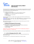
If you are very new to ARM
microcomputers, there’s no
better introductory book
than “The Insider’s Guide
to the Philips ARM7Based Microcontrollers”
by Trevor Martin. Martin is
an executive of Hitex, a UK
vendor of embedded
microcomputer development
software and hardware and
he obviously understands
his material.
You can download this ebook for free from the Hitex
web site.
http://www.hitex.co.uk/arm/l
pc2000book/index.html
There is a controversial
section in Chapter 2 with
benchmarks showing that
the GNU toolset is 4 times
slower in execution
performance and 3.5 times
larger in code size than
other professional compiler
suites for the ARM
microprocessors. Already
Mr. Martin has been challenged about these benchmarks on the internet message
boards; see “The Dhrystone benchmark, the LPC2106 and GNU GCC” at this web
address:
http://www.compuphase.com/dhrystone.htm
Well, we can’t fault Trevor Martin for tooting his own horn! In any case, Martin’s book is
a magnificent work and it would behoove you to download and spend a couple hours
reading it. I’ve used Hitex tools professionally and can vouch for their quality and value.
Read his book! Better yet, it’s required reading.
My purpose in this tutorial is to guide the student or hobbyist through the myriad of
documentation and web sites containing the necessary component parts of a working
ARM software development environment. I’ve devised a simple sample program that
blinks an LED that is compatible in every way with the GNU assembler, compiler and
linker.
There are two variants of this program; a FLASH-based version and a RAM-based
version. The RAM-based version is limited to the LPC2106 RAM space (64K) but you
can set an unlimited number of software breakpoints. The FLASH-based version can
be burned into onboard flash using the Philips ISP utility and then debugged using
JTAG as long as you limit yourself to two breakpoints (hardware).
If you get this to work, you are well on your way to the fascinating world of embedded
software development. Take a deep breath and HERE WE GO!
Installing the Necessary Components
To set up an ARM cross-development environment using Eclipse, you need to
download and install several components. The required parts of the Eclipse/ARM cross
development system are:
1.
SUN Java Runtime
2.
Eclipse IDE
3.
Eclipse CDT Plug-in for C++/C Development (Zylin custom
version)
4.
CYGWIN GNU C++/C Compiler and Toolset for Windows
5.
GNUARM GNU C++/C Compiler for ARM Targets
6.
Philips Flash Programmer for LPC2100 Family CPUs
7.
OpenOCD for JTAG debugging
JAVA Runtime
Quite a bit of the Eclipse IDE was written in JAVA. Therefore, you must have the JAVA
runtime installed on your Windows computer to run Eclipse. Most people already have
JAVA set up in their Windows system, but just in case you don’t have JAVA installed,
here’s how to do it.
The JAVA runtime is available free at www.sun.com. The following screen will appear.
Click on “Downloads – Java 2 Standard Edition” to continue.
Select the “latest and greatest” Java runtime system by clicking on J2SE 5.0.
Specifically, we need only the Java Runtime Environment (JRE). Click on “Download
JRE 5.0 Update 3.”
The Sun “Terms of Use” screen appears first. You have to accept the Sun binary code
license to proceed. If you develop a commercial product using the Sun JAVA tools, you
will have to pay royalties to them.
Select the “accept” radio
button and click “continue”
to proceed.
One more choice to decide on – we want the “online” installation for Windows.
Here’s a blow-up of the line we must click on. We select “online” so we can install
immediately.
Finally the “file download” window appears. Click on “Run” to download and run the
installation.
`
Now the downloading will start.
After downloading, the installation will proceed automatically.
When the Java Runtime Environment installation completes, you will see this display.
Click on “Finish.”
As a quick check, go to the Windows Start menu and select “Start – Control Panel –
Add or Remove Programs.”
Scroll down the list of installed programs and see if the Java J2SE Runtime
Environment was indeed installed!
The Sun Microsystems web site is very dynamic, changing all the time. Don’t be
surprised if some of the example screen captures shown here are a bit different.
Eclipse IDE
The Eclipse IDE is a complete Integrated Development Environment platform similar to
Microsoft’s Visual Studio. Originally developed by IBM, it has been donated to the
Open-Source community and is now a massive world-wide Open-Source development
project. Eclipse, by itself, is configured to edit and debug JAVA programs. By installing
the CDT plug-ins, you can use Eclipse to edit and debug C/C++ programs (more on
that later). When properly setup, you will have a sophisticated programmer’s editor,
compilers and debugger sufficient to design, build and debug ARM applications.
You can download Eclipse for free at the following web site.
www.eclipse.org
The following Eclipse welcome page will display. Expect some differences from my
example below since the Eclipse web site is very dynamic. Click on “Downloads” to
get things started.
Click on “downloads”
The Eclipse download window will appear. Eclipse is constantly being improved and
new releases come several times a year. Usually the safest thing to download is the
“official” latest release. When this tutorial was created, the latest release was Eclipse
SDK 3.1.1
To modify Eclipse to develop embedded C programs, we will be using the CDT plug-in
developed by the Norwegian company Zylin. You must select the Eclipse release that
matches with the currently available Zylin CDT release (Zylin doesn’t archive old
releases of CDT). As this tutorial was written, the Zylin CDT (version developed on
January 11, 2006) requires the Eclipse 3.2 M4 stable release.
Click on “All Versions” below to find the Eclipse 3.2 M4 Stable Release.
In the upcoming section on the CDT plug-in, we will show how to find out what the
matching versions of CDT and Eclipse are.
Click on Eclipse version 3.2M4 as shown below.
Now click on “eclipse-SDK-3.2M4-win32.zip” to start the download process.
What appears next is a list of download mirror sites that host the Eclipse components. I
selected the University of Buffalo CSE Department in my home town (and where I
got my MSEE degree).
.
.
.
When the mirror site starts the download process, you have to select a destination
directory for the Eclipse zip file. In my case, I created an empty C:/scratch directory on
one of my hard drives (you could use any other drive as well).
First click on Save below.
Now browse to the c:/scratch directory that you created previously.
Click on Save above to start the download.
Now the download will start. Eclipse is delivered as a ZIP file. It’s 112 megabytes in
length and takes 10 minutes to download with my broadband cable modem. If you
have a dialup internet connection, this will be excruciating. If you don’t have a cable
modem high-speed internet connection, I suggest you find somebody who does and go
over there with a blank CDROM and a gift.
When the Eclipse download completes, you should see the following zip file in your
scratch directory.
Eclipse is delivered as a ZIP file (eclipse-SDK-3.2M4-win32.zip). You can use WinZip
to decompress this file and load its constituent parts on your hard drive.
If you don’t have WinZip, you can get a free evaluation version from this address:
http://www.winzip.com/
There’s a decent Help file supplied by WinZip. Therefore, we’re going to assume that
the reader is able to use a tool such as WinZip to extract from zip files.
In my computer, with WinZip installed, double-clicking on the zip file name (eclipseSDK-3.1-win32.zip) in the Windows Explorer display above will automatically start up
WinZip. To be fair, Windows Explorer has features to unzip these files also.
WinZip will ask you into what directory you wish to extract the contents of the zip file. In
this case, you must specify the root drive C:
Click on “Extract” to start the Eclipse file decompression.
The WinZip Utility will start extracting all the Eclipse files and directories into a
c:/eclipse directory on your root drive C:
At this point, Eclipse is already installed (some things are done when you run it for
the first time). The beauty of Eclipse is that there are no entries made into the
Windows registry, Eclipse is just an ordinary executable file. Here’s what the Eclipse
directory looks like at this point.
You can create a desktop icon for conveniently starting Eclipse by right-clicking on the
Eclipse application above and sending it to the desk top.
The Eclipse application is the file eclipse.exe.
Right-click on the Eclipse
application and send it to
the desk top.
Rename the Eclipse
desktop icon to indicate the
exact version running.
Now is a good time to test that Eclipse will actually run. Click on the desktop icon to
start the Eclipse IDE.
If the Eclipse Splash Screen appears, we have succeeded. If not, chances are that the
Java Run Time Environment is not in place. Review and repeat the instructions on
installing Java on your computer.
The first order of business is to specify the location of the Workspace. I choose to
place the workspace within the Eclipse directory. You are free to place this anywhere;
you can have multiple workspaces; here is where you make that choice.
I specified the Eclipse
workspace by just typing
this file specification
directly in the text box.
When you click OK, the Eclipse main screen will start up.
If you made it this far, you now have a complete Eclipse system capable of developing
JAVA programs for the PC. There are a large number of JAVA books and some really
good ones showing how to develop Windows applications with JAVA using the Eclipse
toolkit.
Quite a bit of Eclipse was written in JAVA and this shows you just how sophisticated a
program can be developed with the Eclipse JAVA IDE.
However, the point of this tutorial is to show how the Eclipse platform with the CDT
plug-ins can be used to develop embedded software in C language for the ARM
microcomputers.
Eclipse CDT
Eclipse, just by itself, is designed to edit and debug JAVA programs. To equip it to
handle C and C++ programs, you need to download the CDT (C Development Toolkit)
plug-in. The CDT plug-in is simply zip files that are unzipped into the Eclipse directory.
Unfortunately, the CDT plug-in from the Eclipse web site has some problems
debugging applications in a cross-development environment (e.g. where the target is a
circuit board with an ARM microprocessor and a JTAG interface). To the rescue is the
Norwegian engineering company Zylin who have developed a special custom version
of CDT that properly interfaces the GDB debugger to a remote target. The Zylin
version of CDT was developed with the cooperation of the CDT Development Team
and is essentially a copy of the latest version of CDT with the special debug
modifications. The open source community owes a debt of thanks to Øyvind Harboe
and his associates at Zylin.
To download the Zylin version of the CDT plug-in, click on the following link:
http://www.zylin.com/embeddedcdt.html
Be mindful of this note!
Latest snapshot requires
Eclipse 3.2 or later.
Click on “Latest Snapshot” to see the two zip files you need to download.
Download these two zip files
Therefore, for this tutorial, we will be using the Eclipse Stable Release 3.2M4 in
conjunction with the latest Zylin release of CDT, dated December 13, 2005.
Download the following two files from the Zylin web site.
http://www.zylin.com/embeddedcdt-20051213.zip
http://www.zylin.com/zylincdt-20051213.zip
It is incumbent on the reader to do some research to be sure that the Zylin “latest
snapshot” is fully compatible with the Eclipse version you just downloaded. A
good suggestion is to go through the Zylin web site’s message archives and from that
determine which versions of Eclipse and Zylin CDT are compatible. A message in the
January archive notes:
- NB! Requires >= Eclipse 3.2 M4
First, click on http://www.zylin.com/embeddedcdt-20051213.zip to download.
Then click on “Save” in the File Download window.
Select the temporary c:\scratch directory as the target of the download and click
“Save.”
The first Zylin CDT
will download into
c:\scratch folder.
file is an 11.6 Mb
download.
zip file
the
This
Next, click on http://www.zylin.com/zylincdt-20051213.zip to download.
Then click on “Save” in the File Download window.
Select the temporary c:\scratch directory as the target of the download.
Then click on “Save” in the “Save As” window.
The second Zylin CDT zip file will download into the c:\scratch folder. This file is a
shorter file, only 213 Kb.
Both Zylin CDT download files are now in the c:\scratch folder.
Extract these two files to the
c:\eclipse folder
Select both Zylin CDT files in the c:\scratch folder using Windows Explorer and use
WinZip to extract them to the c:\eclipse folder.
Let’s take a moment to note how marvelously simple Eclipse is to install and update
with plug-ins.
Eclipse is itself a simple executable; it makes no entries into the Windows registry.
Plug-ins are simple zip files that are extracted into the c:\eclipse folder – there’s
nothing else to do. Bravo to the Eclipse team for keeping these things simple!
To verify that Eclipse had the CDT installed properly, start Eclipse by clicking on the
desktop icon.
When Eclipse starts, click on “File – New - Project…”
When the New Project window appears, check if C and C++ appear as potential
projects. If this is true, Eclipse CDT has been installed properly.
If you don’t see the C and C++ listed, here’s what might have happened. It’s possible
to disable the CDT plug-in. To see where this may be done, click “Help – Software
Updates – Manage Configuration”.
If you click on Eclipse C/C++ Development Tools 3.1.0, you will see an option to
disable the CDT plug-in. If this has been disabled, use these menus to reverse this
situation.
CDT Plug-in would
be disabled if
somebody clicked
the “disable” option.
CYGWIN GNU Toolset for Windows
The GNU toolset is an open-source implementation of a universal compiler suite; it
provides C, C++, ADA, FORTRAN, JAVA, and Objective C. All these language
compilers can be targeted to most of the modern microcomputer platforms (such as
the ARM 32-bit RISC microcontrollers) as well as the ubiquitous Intel/Microsoft PC
platforms. By the way, GNU stands for “GNU, not Unix”, really – I’m serious!
Unfortunately for all of us that have desktop Intel/Microsoft PC platforms, the GNU
toolset was originally developed and implemented for the GNU operating system. To
the rescue came Cygwin, a company that created a set of Windows dynamic link
libraries that enable the GNU compiler toolset to run on a Windows platform. If you
install the GNU compiler toolset using the Cygwin system, you can literally open up a
DOS command window on your screen and type in a DOS command like this:
>arm-elf-gcc –g –c
main.c
The above will compile the source file main.c into an object file main.o for the ARM
microcontroller architecture. In other words, if you install the Cygwin GNU toolset
properly, you can forget that the GNU compiler system is GNU/Linux-based.
Normally, the Cygwin installation gives you a compiler toolset whose target
architecture is the Windows/Intel PC platform. It does not include a compiler toolset for
the ARM microprocessors, the MIPS microprocessors, and so forth.
It is possible to build a compiler toolset for the ARM processors using the generic
Cygwin GNU toolkit. In his book “Embedded System Design on a Shoestring”,
Lewin A.R.W. Edwards gives detailed instructions on just how to do that. Fortunately,
there are quite a few pre-built tool chains on the internet that simplify the process. One
such tool chain is GNUARM which gives you a complete set of ARM compilers,
assemblers and linkers. This will be done in the next section of this tutorial.
It’s worth mentioning that the GNUARM tool chain doesn’t include the crucial MAKE
utility, it’s in the Cygwin tool kit we’re about to install. This is why you have to add two
path specifications to your Windows environment; one for the c:/cygwin/bin folder and
one for the c:/programfiles/gnuarm/bin.
The Cygwin site that has the GNU toolset for Windows is:
www.cygwin.com
The Cygwin web site opens as follows:
The first thing to do is to click on the install icon:
We need to download the setup executable and automatically run it.
Click on “Run” to
download and run the
Cygwin setup
program.
Now the Cygwin wizard will start up. Select “Next” to continue.
Choose “Install from Internet” and then click “Next.”
In the next screen below, take the default directory c:/Cygwin. Also, check “Just Me”
and “DOS / text”.
Click “Next” to continue.
Now we specify a directory where all the downloaded components go, our c:/scratch
folder will do just fine.
Since I have a high speed internet connection, I always select “Direct Connection.”
Click “Next” to continue.
Now the Cygwin Installer presents you with a list of mirror sites that can deliver the
Cygwin GNU Toolkit. It’s a bit of a mystery which one to choose; I picked
http://planetmirror.com because it sounds cool. You may have to experiment to find
one that downloads the fastest. Click “Next” to continue.
Cygwin will download a few bits for a couple of seconds and then display this “Select
Packages” list allowing you to tailor exactly what is included in the down load.
The screen above allows you to specify what GNU packages you wish to install.
Basically, we want an installation that will allow us to compile for the Windows XP /
Intel platform. This will allow us to use Eclipse to build Windows applications (not
covered in this document). Remember that we’ll be installing the GNUARM suite of
compilers, linkers etc. for the ARM processor family shortly.
If you look at the Cygwin “Select Packages” screen below, you’ll see the following line.
You
the little circle with the two arrowheads until the line changes to this:
must click on
This will force installation of the default GNU compiler suite for Windows/Intel targets.
Here’s the “Select Packages” screen before clicking on the circle with arrowheads.
The following four packages must be selected and changed from “default” to “install.”
Archive
Devel
Libs
Web
Default
Default
Default
Default
Archive
Devel
Libs
Web
Install
Install
Install
Install
Click on the little circle with the arrowheads until you change the four packages listed
above from “default” to “install.” You should see the screen displayed directly below.
Note that the Archive, Devel, Libs and Web components are selected for “Install”.
Everything else is left as “default.”
Click “Next’ to start the download.
Now the Cygwin will start downloading. This creates a huge 700 Megabyte directory on
your hard drive and takes 30 minutes to download and install using a cable modem.
When the installation completes, Cygwin will ask you if you want any desktop icons
and start menu entries set up. Say “No” to both. These icons allow you to bring up the
BASH shell emulator (like the command prompt window in Windows XP). This would
allow you do some Linux operations, but this capability is not necessary for our
purposes here. Click on “Finish” to complete the installation.
Now the Cygwin installation manager completes and shows the following result.
The directory c:\cygwin\bin must be added to the Windows XP path
environment variable. This allows Eclipse to easily find the Make utility, etc.
Using the Start Menu, go to the Control Panel and click on the “System” icon.
Then click on the “Advanced” tab and select the “Environment Variables” icon.
Highlight the “Path” line and hit the “Edit” button. Add the addition to the path as
shown in the dialog box shown below (don’t forget the semicolon separator). The
Cygwin FAQ advises putting this path specification before all the others.
We are now finished with the CYGWIN installation. It runs silently in the background
and you should never have to think about it again.
Downloading the GNUARM Compiler Suite
At this point, we have all the GNU tools needed to compile and link software for
Windows/Intel computers. It is possible to use all this to build a custom GNU compiler
suite for the ARM processor family. The very informative book “Embedded System
Design on a Shoestring” by Lewin A.R.W. Edwards ©2003 describes how to do this
and it is rather involved.
Fortunately, Rick Collins, Pablo Bleyer Kocik and the people at gnuarm.com have
come to the rescue with pre-built GNU compiler suite for the ARM processors. Just
download it with the included installer and you’re ready to go.
Click on the following link to download the GNUARM package.
www.gnuarm.com
The GNUARM web site will display and you should click on the “Files” tab.
The correct package to download is Binaries Cygwin – GCC- 4.0.1-c-c++ toolchain
Download
this file
Just like all the other downloads we’ve done, we direct this one to our empty download
directory on the hard drive. Here we click “Save” and then specify the download
destination.
Once again, our c:/scratch directory will suffice. As you can see, this download has a
very long name!
Click “Save” to start the download.
This download is a 18 megabyte file and takes 30 seconds on a cable modem.
The download directory now has the following setup application with the following
unintelligible filename: bu-2.16.1_gcc-4.0.2-c-c++-java_nl-1.14.0_gi-6.4.exe
Click on that filename to start the installer.
Click on this
application to start
the GNUARM
installer
The GNUARM installer will now start. Click “Next” to continue.
Accept the GNU license agreement – don’t worry, it’s still free. Click “Next” to
continue.
We’ll take the default and let it install into the “Program Files” directory. Click “Next”
to continue.
We’ll also take the defaults on the “Select Components” window. Click “Next” to
continue.
Take the default on this screen. Click “Next” to continue.
It’s very important that you don’t check “Install Cygwin DLLs” below. We already
have the Cygwin DLLs installed from our Cygwin environment installation. In fact, the
ARM message boards have had recent comments suggesting that the Cygwin DLL
installation from within GNUARM has some problems.
Since all operations are called from within Eclipse, we don’t need a “desktop icon”
either. Click “Next” to continue.
Click on “Install” to start the GNUARM installation.
Sit back and watch the GNUARM compiler suite install itself.
When it completes, the following screen is presented. Make sure that “Add the
executables directory to the PATH variable” is checked. This is crucial.
This completes the installation of the compiler suites. Since Eclipse will call these
components via the make file, you won’t have to think about it again.
It’s worth mentioning that the GNUARM web site has a nice Yahoo user group with
other users posing and answering questions about GNUARM. Pay them a visit. The
GNUARM web site also has links to all the ARM documentation you’ll ever need.
Installing the Philips LPC2000 Flash Utility
into Eclipse
The Philips LPC2000 Flash Utility allows downloading of hex files from the COM1 port
of the desktop computer to the Olimex LPC-P2106 board’s flash (or RAM) memory.
We need to download the latest version of this program from the Philips web site and
unzip and install it into the program files directory. Then we will start Eclipse and add
the LPC2000 Flash Utility as an external tool to be invoked.
Click on the following link to access the Philips LPC2106 web page.
www.semiconductors.philips.com/pip/LPC2106.html
The following web page for the LPC2106 should open.
If you scroll down this page, you will see a link to the LPC2000 Flash Utility download.
Click on the ZIP file LPC2000 Flash Utility (date 2004-03-01)
As before, we’ll save the downloaded zip file in our empty c:/scratch directory.
This is a fairly
short download,
only about 2
megabytes.
We’ll use WinZip to unzip this into the c:/scratch directory. I’m assuming, at this point,
that you have WinZip manipulations well understood.
`Now you can see that the download directory has a setup utility and another zip file
containing the LPC2000 Hex Utility.
Click on the setup.exe application to start the installer.
Click on setup to
start the installer
The LPC2000 Flash Utility setup now starts. Click on OK to proceed.
Take the default on this screen below and let it install the LPC2000 Flash Utility into
the Program Files directory.
In a very few seconds, the installer will complete and you should see this screen.
Here we see the utility residing in the Program Files directory, just as promised.
Now that the Philips LPC2000 Flash Utility is properly installed on our computer, we’d
like to install it into Eclipse so that it can be invoked from the RUN pull-down menu
under the “external tools” option. Start Eclipse by clicking on the desktop icon.
The layout of the Eclipse screen is called a “perspective.” The default perspective is
the “resource” perspective, as shown below.
We need to change it into the C/C++ perspective. In the Window pull-down menu,
select Window – Open Perspective – Other – C/C++ and then click OK.
Eclipse will now switch to the C/C++ perspective shown below and will remember it
when you exit.
Now we want to add the Philips LPC2000 Flash Utility to the “External Tools” part of
the Run pull-down menu. Select RUN – External Tools – External Tools.
We want to add a new program to the External Tools list, so click on Program and
then New.
Note below that there’s a new program under the “program” tree with the name
New_configuration and there’s no specifications as to what it is.
In the Name text box, replace New-configuration with LPC2000 Flash Utility.
In the Location text box, use the “Browse File System” tool to find the Philips
LPC2000 Flash Utility in the Program Files directory. Its name is LPC210x_IPC.exe.
Here’s the External Tools window before editing.
Here’s the External Tools window after our modifications. Click on Apply to accept.
Close everything out and return to the Run pull-down menu. Select Run – External
Tools – Organize Favorites.
We’re now going to put the Philips PLC2000 Flash Utility into the “favorites” list. Click
on “Add” in the window below.
Click the selection box for LPC2000 Flash Utility. This will add it to the favorites list.
Now when we click on the Run pull-down menu and select “External Tools,” we see
the LPC2000 Flash Utility at the top of the list.
Click on LPC2000 Flash Utility to verify that it runs.
Now cancel the LPC2000 Flash Utility and quit Eclipse.
Installing the OpenOCD Utility
Eclipse/CDT has a fabulous graphical debugger that is built around the venerable GNU
GDB command line debugger. The only problem is how to connect it to a remote target
such as a microprocessor circuit board. GDB communicates to the target via a Remote
Serial Protocol that can be utilized over a serial port or an internet port.
In the past, most people have used the Macraigor OCDRemote utility that reads GDB
serial commands and manipulates the ARM JTAG lines using the PC’s parallel port
and a simple level-shifting device called a “wiggler”. The Macraigor OCDRemote utility
has always been available for free (in binary form) but it is not Open Source. Macraigor
could withdraw it at any time.
To the rescue is German college student Dominic Rath who developed an open source
ARM JTAG debugger as his diploma thesis at the University of Applied Sciences, FHAugsburg in Bavaria. Dominic’s thesis can be found here:
http://openocd.berlios.de/thesis.pdf
Dominic also has a website on the Berlios Open Source repository here:
http://openocd.berlios.de/web/
To retrieve the OpenOCD utility, click on the following link.
http://prdownload.berlios.de/openocd/openocd-cygwin-20060213.tar.gz
Once again, let’s save it to the c:/scratch folder.
OpenOCD will now download into the empty c:/scratch folder.
This is an uncompressed Unix-style “Tape Archive” tar file that can be unpacked by
the utility WinRAR. WinRAR is a shareware utility that has a 40 day free trial period
and can be found here:
http://www.rarlab.com/rar/wrar351.exe
Once WinRAR has unpacked the files, the c:/scratch folder now contains:
The folder c:\scratch\openocd shown above has two files we need to copy to the
c:/Program Files/GNUARM/bin directory. The two files are:
C:\scratch\openocd\src\openocd.exe
executable)
(The OpenOCD
C:\scratch\openocd\doc\configs\arm7_wig.cfg
the “wiggler” )
(configuration file for
While this may seem a bit arbitrary, our GNUARM folder c:\Program
Files\GNUARM\bin contains the ARM versions of the GNU C compiler and other
utilities and will have a path defined to it!
After copying these files to the c:/Program Files/GNUARM/bin folder, verify that the
two files are there!
The wiggler configuration file, just a list of OpenOCD commands run at startup that
configure the debugger for the parallel port and the wiggler, can be left in its default
state for the Eclipse system. It would be wise to inspect Dominic Rath’s documentation
since the appendix has the up-to-date list of OpenOCD commands.
Now that OpenOCD is properly installed on our computer, we’d like to install it into
Eclipse so that it can be invoked from the RUN pull-down menu under the “external
tools” option. We also need to install the utility “IOPerm.exe” into Eclipse to allow
OpenOCD to access the parallel printer port. IOPerm.exe is already part of your
Cygwin installation and may be found in the c:\cygwin\bin folder.
Start Eclipse by clicking on the desktop icon. Make sure the C/C++ perspective is
displayed.
Now we want to add the OpenOCD utility to the “External Tools” part of the Run pulldown menu. Select RUN – External Tools – External Tools.
In the “External Tools” window, click on “Program” and then “New” to create a new
External Tool configuration.
Now fill in the External Tools configuration window as shown below. Click on “Apply”
and then “Close” to accept the OpenOCD configuration.
Now let’s put OpenOCD into the Favorites list. Click on “Run” followed by “External
Tools” and “Organize Favorites…”
Click on “Add” and then check “OpenOCD” for inclusion into the Favorites list.
Click on “OK” to enter the selection.
Click “OK” on the “Organize External Tools …” window to complete the process.
The check our work, click on the “External Tools” toolbar button’s pull-down arrow to
see if OpenOCD was added to the Favorites list.
Installing the IOPERM Utility
OpenOCD requires that the GNU utility IOPerm.exe be running to allow OpenOCD
access to the PC’s parallel port. This utility is already in the c:\cygwin\bin directory. All
we need to do is add this utility as an “External Tool” and add it to the Favorites list.
Click on “Run” followed by “External Tools” followed by “External Tools…”
In the “External Tools” window, click on “New” to create a new External Tools
configuration.
Now fill out the form as shown below. IOPerm.exe can be found in the c:\cygwin\bin
folder.
One argument is needed, in this case:
-i
Click on “Apply” then “Close” to accept the new External Tool.
This is
-i
Using the same techniques outlined above, enter IOPerm into the External Tools
Favorites list.
Using the same techniques utilized previously, add IOPerm to the list of favorites in the
“external tools”.
Click on the External Tools toolbar button’s pull-down arrow to check that IOPerm has
been added to the list of favorites.
Verifying the PATH Settings
There is one final and very crucial step to make before we complete our tool building.
We have to ensure that the Windows PATH environment variable has entries for the
Cygwin toolset, the GNUARM toolset and the OCDRemote JTAG server.
These are the three paths that must be present in the Windows environment:
c:\cygwin\bin
c:\program files\gnuarm\bin
c:\cygwin\usr\local\bin
To verify that these paths are present in Windows and to make changes if required,
start the Windows Control Panel by clicking “Start – Control Panel”.
Now click on the “Advanced” tab below.
Now click on the “Environment Variables” button.
In the Environment Variables window, find the line for “Path” in the System Variables
box on the bottom, click to select and highlight it and then click on “Edit”.
Take a very careful look at the “Edit System Variable” window (the Path Edit, in this
case).
You should see the following paths specified, all separated by semicolons. The path is
usually long and complex; you may find the bits and pieces for GNUARM interspersed
throughout the path specification. I used cut and paste to place all my path
specifications at the beginning of the specification (line); this is not really necessary.
You should see the following paths specified.
c:\cygwin\bin;c:\program files\gnuarm\bin;c:\cygwin\usr\local\bin
If any of the three is not present, now is the time to type them into the path
specification.
I’ve found that not properly setting up the Path specification is the most common
mistake made in configuring Eclipse to do cross-development.
This completes the setup of Eclipse and all the ancillary tools required to cross develop
embedded software for the ARM microcomputer family (Philips LPC2000 family in
specific).
If you stayed with me this far, as Yoda would say, “
patience will be!”
Rewarded soon, your
Creating a Simple Eclipse Project
At this point, we have a fully-functioning Eclipse IDE capable of building C/C++
programs for the ARM microprocessor (specifically for the Olimex LPC-P2106
prototype board).
We will now create an Eclipse C project called “demo2106_blink_flash” that will blink
the board’s red LED_J which is I/O port P0.7. This demo uses no interrupts and runs
totally out of onboard flash memory. It has been intentionally designed to be as simple
and as straightforward as possible. Think of it as the embedded software equivalent of
“Hello World!”
Click on our Eclipse desktop icon to start Eclipse.
Eclipse should start and present the C/C++ perspective as shown below. Select
“Window - Open Perspective – Other - C/C++” if you are not in the C/C++
perspective.
To create a project, select File – New – New Project - Standard Make C Project from
the File pull-down menu and click “Next” to continue.
You should see the “New Project” dialog box and enter the project name
(demo2106_blink_flash) in the box as shown below. Click on Next to continue.
The New Project dialog box appears next. If you click on the “Make Builder” tab,
you’ll notice that Eclipse build command is “make.” Make is provided by the Cygwin
GNU tools.
Take the default on the “Build
Command”, Eclipse will always issue a
“make” command to build your project.
These are the targets that
“make” will run when you
hit the Build All, Build
Project or Clean toolbar
buttons.
Let’s remind ourselves that we installed the Cygwin GNU tools earlier in the tutorial
and the Windows Explorer will show that the make.exe file is indeed in the directory
c:/cygwin/bin, as shown below.
This is a good time to point out the differences between “Build All”, “Build Project” and
“Clean.”
Build All
It will first clean (delete) all object, list and output files.
Then it will rebuild everything, whether needed or not.
Build Project
This will not clean (delete) anything.
It will only compile those source files that are “out-of-date.”
Clean
Will clean (delete) all object, list and output files.
This is no different from opening up a DOS command window and typing the command
in directly, such as.
> make clean all
If you click “Finish” on the “New Project” dialog, Eclipse will return to the C/C++
Perspective.
Now the C/C++ perspective shows a bona fide project in the “C/C++ projects” box on
the left. As of now, there are no source files created.
We can now use Eclipse/CDT’s import feature to copy the source files into the project.
The source files for the example projects are here: xxxxxxxxxxx
Assuming that you successfully unzipped the “demo2106_blink_flash.zip” project
files associated with this tutorial to an empty directory such as c:/scratch, you should
have the following source and make files in that directory.
Click on the “File” pull-down menu and then click on “Import,” then in the “Import”
window, click on “File System.”
When the “Import – File System” window appears, click on the “Browse” button. Hunt
for the sample project which is stored in the c:/scratch/ directory.
Click on the directory “scratch” and hit the “OK” button in the “Import from directory”
window on the left below.
Click on “Select All” in the Import
window below right to get the source
files selected for import into our
project.
Now we have to indicate the destination for our source files. Click on “Browse” on the
line to the right that says “Into Folder:”
The proper destination folder appears in the Import Into Folder window below.
Click on the folder name “demo2106_blink_flash” and click “OK.” The directory name
“demo2106_blink_flash” should appear in the text box.
Now the Import dialog is completely filled out; we can click on “Finish” to actually
import the source files into our project.
Now the C/C++ perspective main screen will reappear. Click on the “+” expand symbol
in the navigator pane to see if our files have been transferred.
Success is at hand, the expanded Projects view in the Navigator pane on the left
shows our imported files.
Description of the LPC210X.H Include File
Let’s look at the lpc210x.h header file. Double-click on it in the Project pane on the left.
ARM peripherals are memory-mapped, so all I/O registers are defined in this file so
you don’t have to type in the absolute memory addresses. This file is quite large.
//********************************************************************
// LPC210X.H: Header file for Philips LPC2104 / LPC2105 / LPC2106
//
// *******************************************************************
#ifndef __LPC210x_H
#define __LPC210x_H
/* Vectored Interrupt Controller (VIC) */
#define VICIRQStatus
(*((volatile unsigned
#define VICFIQStatus
(*((volatile unsigned
#define VICRawIntr
(*((volatile unsigned
#define VICIntSelect
(*((volatile unsigned
#define VICIntEnable
(*((volatile unsigned
#define VICIntEnClr
(*((volatile unsigned
#define VICSoftInt
(*((volatile unsigned
#define VICSoftIntClr (*((volatile unsigned
#define VICProtection (*((volatile unsigned
long
long
long
long
long
long
long
long
long
*)
*)
*)
*)
*)
*)
*)
*)
*)
0xFFFFF000))
0xFFFFF004))
0xFFFFF008))
0xFFFFF00C))
0xFFFFF010))
0xFFFFF014))
0xFFFFF018))
0xFFFFF01C))
0xFFFFF020))
/* Pin Connect Block */
#define PINSEL0
(*((volatile unsigned long *) 0xE002C000))
#define PINSEL1
(*((volatile unsigned long *) 0xE002C004))
/* General Purpose Input/Output (GPIO) */
#define IOPIN
(*((volatile unsigned
#define IOSET
(*((volatile unsigned
#define IODIR
(*((volatile unsigned
#define IOCLR
(*((volatile unsigned
long
long
long
long
*)
*)
*)
*)
0xE0028000))
0xE0028004))
0xE0028008))
0xE002800C))
. . . file continues . . .
For example, to set bit 7 of P0, we can simply write:
IOSET = 0x00000080;
// turn P0.7 (red LED) off
Description of the Startup File CRT.S
Now let’s look on the startup assembler file, crt.s.
/* ***********************************************************************************
crt.s
STARTUP ASSEMBLY CODE
-----------------------
Module includes the interrupt vectors and start-up code.
**************************************************************************************
/* Stack Sizes */
.set UND_STACK_SIZE,
.set ABT_STACK_SIZE,
.set FIQ_STACK_SIZE,
.set IRQ_STACK_SIZE,
.set SVC_STACK_SIZE,
0x00000004
0x00000004
0x00000004
0X00000004
0x00000004
/*
/*
/*
/*
/*
stack
stack
stack
stack
stack
for
for
for
for
for
"undefined instruction" interru
"abort" interrupts is 4 bytes *
"FIQ" interrupts is 4 bytes */
"IRQ" normal interrupts is 4 by
"SVC" supervisor mode is 4 byte
/* Standard definitions of Mode bits and Interrupt (I & F) flags in PSRs (program stat
.set MODE_USR, 0x10
/* Normal User Mode */
.set MODE_FIQ, 0x11
/* FIQ Processing Fast Interrupts Mode */
.set MODE_IRQ, 0x12
/* IRQ Processing Standard Interrupts Mode *
.set MODE_SVC, 0x13
/* Supervisor Processing Software Interrupts
.set MODE_ABT, 0x17
/* Abort Processing memory Faults Mode */
.set MODE_UND, 0x1B
/* Undefined Processing Undefined Instructio
.set MODE_SYS, 0x1F
/* System Running Privileged Operating Syste
.set
.set
I_BIT, 0x80
F_BIT, 0x40
/* when I bit is set, IRQ is disabled (progr
/* when F bit is set, FIQ is disabled (progr
/* GNU assembler controls */
.text
.arm
.align
/* all assembler code that follows will go i
/* compile for 32-bit ARM instruction set */
/* align section on 32-bit boundary */
/* Global symbols */
.global
Reset_Handler
.global
_startup
/* Exception Vectors */
_startup:
ldr
ldr
ldr
ldr
ldr
nop
ldr
ldr
Reset_Addr:
Undef_Addr:
SWI_Addr:
PAbt_Addr:
DAbt_Addr:
IRQ_Addr:
.word
.word
.word
.word
.word
.word
PC,
PC,
PC,
PC,
PC,
Reset_Addr
Undef_Addr
SWI_Addr
PAbt_Addr
DAbt_Addr
PC, [PC,#-0xFF0]
/* Reserved Vector (holds Philips ISP
/* see page 71 of "Insiders Guide to t
/*ARM7-Based Microcontrollers" by Trev
PC, FIQ_Addr
Reset_Handler
UNDEF_Routine
SWI_Routine
UNDEF_Routine
UNDEF_Routine
IRQ_Routine
/*
/*
/*
/*
/*
/*
defined
defined
defined
defined
defined
defined
in
in
in
in
in
in
this module below */
main.c */
main.c */
main.c */
main.c */
main.c */
FIQ_Addr:
.word
.word
FIQ_Routine
0
/* defined in main.c */
/* rounds the vectors and ISR addresse
/* Reset Handler */
Reset_Handler:
/* Setup a stack for each mode - note that this only sets up a usabl
for User mode.
Also each mode is setup with interrupts initially
ldr
r0, =_stack_end
msr
CPSR_c, #MODE_UND|I_BIT|F_BIT
/* Undefined Instruction M
mov
sp, r0
sub
r0, r0, #UND_STACK_SIZE
msr
CPSR_c, #MODE_ABT|I_BIT|F_BIT
/* Abort Mode */
mov
sp, r0
sub
r0, r0, #ABT_STACK_SIZE
msr
CPSR_c, #MODE_FIQ|I_BIT|F_BIT
/* FIQ Mode */
mov
sp, r0
sub
r0, r0, #FIQ_STACK_SIZE
msr
CPSR_c, #MODE_IRQ|I_BIT|F_BIT
/* IRQ Mode */
mov
sp, r0
sub
r0, r0, #IRQ_STACK_SIZE
msr
CPSR_c, #MODE_SVC|I_BIT|F_BIT
/* Supervisor Mode */
mov
sp, r0
sub
r0, r0, #SVC_STACK_SIZE
msr
CPSR_c, #MODE_SYS|I_BIT|F_BIT
/* System Mode */
mov
sp, r0
1:
2:
/* copy
ldr
ldr
ldr
cmp
ldrlo
strlo
blo
.data section (Copy from ROM to RAM) */
R1, =_etext
R2, =_data
R3, =_edata
R2, R3
R0, [R1], #4
R0, [R2], #4
1b
/* Clear .bss section (Zero init) */
mov
R0, #0
ldr
R1, =_bss_start
ldr
R2, =_bss_end
cmp
R1, R2
strlo
R0, [R1], #4
blo
2b
/* Enter the C code
b
main
*/
.end
The first part of the crt.s file above has some symbols set to the various stack sizes
and mode bits.
The next part
of the crt.s file, shown above, sets up the interrupt vectors.
Note that all of the code and data that follows goes into the .text section. It is also in
ARM 32-bit code (not Thumb). Two labels are made global, _startup and
Reset_Handler. These will be available to other modules in the project and will also
appear in the map. The GNU assembler doesn’t require you .extern anything. If a
symbol is not defined in the assembler file, it is automatically assumed to be external
and defined elsewhere. The vector table is 32 bytes long and is required to be placed
at address 0x000000. You will see later in this tutorial that the interrupt service routines
referenced in the Vector Table are just endless-loop stubs in the main.c function and
the interrupts are turned off.
The NOP instruction
at address 14 in the vector table is an empty spot to hold the
checksum. Page 179 of the Philips LPC2106 manual states:
The reserved ARM interrupt vector location (0x0000 0014) should contain
the 2’s complement of the check-sum of the remaining interrupt vectors.
This causes the checksum of all of the vectors together to be 0.
Before you fall on your sword, you’ll be happy to know that the Philips Flash Loader
and OpenOCD will calculate that checksum and insert it for you. That’s why we show it
as a NOP.
One of my favorite bits of ARM magic is this instruction, in the vector table above:
ldr
PC, [PC,#-0xFF0]
This instruction, the IRQ vector, is at address 0x00000018. Adding 8 to that to account
for the pipeline, we get an effective address of 0x00000020 which is where the PC
really is in the pipeline at this instant. Subtracting 0xFF0 from this gives an address of
0xFFFFFF20 which just happens to be the Vector Address Register (which contains
the address of the IRQ interrupt service routine that should be run). Therefore, this
single instruction loads into the PC the address of the IRQ exception routine that
should be executed. An excellent description of this may be found on page 319 in the
book “ARM System Developer’s Guide” by Andrew N Sloss, Dominic Symes and
Chris Wright.
The next part
stacks.
of crt.s, shown above, sets up the various interrupt modes and
The label Reset_Handler is the beginning of the startup code. Recall that the first
interrupt vector at address 0x000000 loads the PC with the contents of the address
Reset_Addr, which itself contains the address of the startup code at the label
Reset_Handler. This trick, used in the entire vector table, loads a 32-bit constant into
the PC and thus can jump to any address in memory space. If you had instead placed
a simple branch immediate instruction in the vector table, you’d be limited to the 24-bit
immediate destination (16777216 bytes from the vector table).
_vectors:
Reset_Addr:
ldr
PC, Reset_Addr
:
.word Reset_Handler
Whenever the LPC2106 is reset, the instruction at 0x000000 is executed first; it jumps
to Reset_Handler. From that point, we are off and running!
The first part of the startup code above sets up the stacks and the mode bits.
The symbol _stack_end will be defined in the linker command script file
demo2106.cmd. Here is how it will be defined. Knowing that the Philips ISP Flash
Loader will use the very top 288 bytes of RAM for its internal stack and variables, we’ll
start our application stacks at 0x4000FEE0 (Note: 0x40010000 – 0x120 =
0x4000FEE0).
/* define a global symbol _stack_end, placed at the very end of RAM
(minus 4 bytes) */
stack_end = 0x4000FEE0 – 4;
Working that out with the Windows calculator, the _stack_end is placed at 4000FEDC.
The five modes undefined, irq, fiq, abort and svc all have their own private copies of
R13 (sp) and r14 (link return). The FIQ mode has additionally private copies of
registers R8 – R14.
The code snippet that sets up the stacks and modes is a bit complex, so let’s explain it
a bit.
First we load R0 with the address of the end of the stack, as described above.
ldr r0, =_stack_end
Now we put the ARM into Undefined Instruction mode by setting the MODE_UND bit in
the Current Program Status Register (CPSR). Thus, by writing R0 into the stack
pointer sp (R13), it will use 0x4000FEDC as the initial stack pointer if we ever have
processing of an undefined instruction. As mentioned above, Undefined Instruction
mode has its own private copies of R13 and R14. By subtracting the undefined stack
size (4 bytes) from R0, we’re limiting the stack for UND mode to just 4 bytes.
msr CPSR_c, #MODE_UND|I_BIT|F_BIT
in undefined mode */
mov sp, r0
UND mode is 0x40000FEDC */
sub r0, r0, #UND_STACK_SIZE
0x4000FED8 */
/* This puts the CPU
/* stack pointer for
/* Register R0 is now
Now we put the ARM into Abort mode by setting the MODE_ABT bit in the CPSR. As
mentioned above, abort mode has its own private copies of R13 and R14. We now set
the abort mode stack pointer to 0x4000FED8. Again by subtracting the abort stack size
from R0, we’re limiting the stack for ABT mode to just 4 bytes.
msr CPSR_c, #MODE_ABT|I_BIT|F_BIT
Abort mode */
mov sp, r0
ABT mode is 0x4000FED8 */
sub r0, r0, #ABT_STACK_SIZE
0x4000FED4 */
/* this puts CPU in
/* stack pointer for
/* Register R0 is now
Now we put the ARM into FIQ (fast interrupt) mode by setting the MODE_FIQ bit in the
CPSR. As mentioned above, FIQ mode has its own private copies of R14 through R8.
We now set the abort mode stack pointer to 0x4000FED4. Again by subtracting the
abort stack size from R0, we’re limiting the stack for FIQ mode to just 4 bytes. We’re
not planning to support FIQ interrupts in this example.
msr CPSR_c, #MODE_FIQ|I_BIT|F_BIT
FIQ mode */
mov sp, r0
FIQ mode is 0x4000FED4
sub r0, r0, #FIQ_STACK_SIZE
0x4000FED0 */
/* this puts CPU in
/* stack pointer for
/* Register R0 is now
Now we put the ARM into IRQ (normal interrupt) mode by setting the MODE_IRQ bit in
the CPSR. As mentioned above, IRQ mode has its own private copies of R13 and R14.
We now set the IRQ mode stack pointer to 0x4000FDE0. Again by subtracting the IRQ
stack size from R0, we’re limiting the stack for IRQ mode to just 4 bytes. We’re not
planning to support IRQ interrupts in this example.
msr CPSR_c, #MODE_IRQ|I_BIT|F_BIT
IRQ mode */
mov sp, r0
IRQ mode is 0x4000FED0 */
sub r0, r0, #IRQ_STACK_SIZE
0x4000FECC */
/* this puts the CPU in
/* stack pointer for
/* R0 is now
Now we put the ARM into SVC (Supervisor) mode by setting the MODE_SVC bit in the
CPSR. As mentioned above, SVC mode has its own private copies of R13 and R14.
We now set the supervisor mode stack pointer to 0x4000FDDC. Again by subtracting
the SVC stack size from R0, we’re sizing the stack for SVC mode to 4 bytes.
msr CPSR_c, #MODE_SVC|I_BIT|F_BIT
in SVC mode */
mov sp, r0
SVC mode is 0x4000FECC */
sub r0, r0, #SVC_STACK_SIZE
0x4000FEC8 */
/* This puts the CPU
/* stack pointer for
/* R0 is now
The ARM “User” mode and the ARM “System” mode share the same registers and
stack. For this very simple example, we’ll run the application in “System” mode. Setting
up the stack for System mode also sets up the stack for System mode. System mode
is the same as User mode but it has more privileges.
Finally we put the ARM into SYSTEM (sys) mode by setting the MODE_SYS bit in the
CPSR. We now set the SYS mode stack pointer to 0x4000FEC8.
msr CPSR_c, #MODE_SYS|I_BIT|F_BIT
mov sp, r0
/* System Mode */
To summarize the above operations, let’s draw a diagram of the stacks we just created.
RAM STACK USAGE
0x40010000
0x4000FFFF
RAM
last address in internal
Philips ISP Flash Loader
Stack and variables
(288. bytes)
Undefined mode stack ( 4 bytes )
Abort mode stack
( 4 bytes )
0x4000FEE0 bottom of Philips ISP
stack
0x4000FEDC UND stack pointer
0x4000FED8
ABT stack pointer
The next part
shown above.
of the startup file crt.s initializes the .data and .bss sections, as
The .data section contains all the initialized static and global variables. The GNU linker
will create an exact copy of the variables in flash with the correct initial values loaded
and place this copy right after the last .text section created. The onus is on the
programmer to copy this initialized flash copy of the data to RAM.
The location of the start of the .data section in flash is defined by symbol _etext
(defined in the linker command script demo2106.cmd). Likewise, the location of the
start and end of the .data section in destination RAM is given by the symbols _data
and _edata. Both of these symbols are defined in the linker command script.
The .bss section contains all the uninitialized static and global variables. All we have to
do here is clear this area. Likewise, the location of the start and end of the .bss section
in destination RAM is given by the symbols _bss_start and _bss_end. Both of these
symbols are defined in the linker command script.
Two simple assembly language loops load the .data section in RAM with the initializers
in flash and clear out the .bss section in RAM.
The GNU linker specifies two addresses for sections, the Virtual Memory Address
(VMA) and the Load memory Address (LMA). The VMA is the final destination for the
section; for the .data section, this is the RAM address where it will reside. The LMA is
where it will be loaded in Flash memory, the exact copy with the initial values. The
GNU Linker will sort this out for us.
Description of the Main Program main.c
Now let’s look at the main program.
The main program starts out with a few function prototypes. Note that the interrupt
routines mentioned in the crt.s assembler program reside in the main() program.
We’ve used the GNU C compiler syntax that identifies the interrupt routines and makes
sure that the compiler will save and restore registers, etc. whenever the interrupt is
asserted.
I’ve also included a few do-nothing variables, both initialized and uninitialized, to
illustrate that the compiler will put the initialized variables into the .data section and the
uninitialized ones into the .bss section.
// ***********************************************************************************
//
main()
//
//
main program blinks the red LED P0.7 in an endless loop
//
//
does not use interrupts!
//
this is the embedded software world's equivalent of "Hello World"
//
// ***********************************************************************************
// *********************************************************
//
Function declarations
// ********************************************************* */
void Initialize(void);
void feed(void);
void
void
void
void
IRQ_Routine (void)
FIQ_Routine (void)
SWI_Routine (void)
UNDEF_Routine (void)
__attribute__
__attribute__
__attribute__
__attribute__
((interrupt("IRQ")));
((interrupt("FIQ")));
((interrupt("SWI")));
((interrupt("UNDEF")));
// **********************************************************
//
Header files
// **********************************************************/
#include "LPC210x.h"
//**********************************************************
//
Global Variables
// **********************************************************/
int
q;
// global uninitialized variable
int
r;
// global uninitialized variable
int
s;
// global uninitialized variable
short h = 2;
short i = 3;
char j = 6;
// global initialized variable
// global initialized variable
// global initialized variable
// **********************************************************
//
MAIN
// **********************************************************/
int
main (void) {
int
static int
static char
static int
static long
static char
static int
const char
j;
a,b,c;
d;
w = 1;
x = 5;
y = 0x04;
z = 7;
*pText = "The Rain in Spain";
// Initialize the system
Initialize();
// set io pins for led P0.7
//
//
//
//
//
//
//
//
loop counter (stack varia
static uninitialized vari
static uninitialized vari
static initialized variab
static initialized variab
static initialized variab
static initialized variab
pointer to const text
IODIR |= 0x00000080;
IOSET = 0x00000080;
IOCLR = 0x00000080;
// pin P0.7 is an output, everything else is input after
// led off
// led on
// endless loop to toggle the red
while (1) {
LED P0.7
for (j = 0; j < 500000; j++ );
IOSET = 0x00000080;
for (j = 0; j < 500000; j++ );
IOCLR = 0x00000080;
//
//
//
//
wait 500 msec
red led off
wait 500 msec
red led on
}
}
// **********************************************************
//
Initialize
// **********************************************************/
#define PLOCK 0x400
void Initialize(void)
//
//
//
//
//
//
//
//
//
//
//
//
//
//
//
//
//
//
//
//
//
//
PLLCFG)
//
//
//
//
//
//
//
//
{
Setting the Phased Lock Loop (PLL)
---------------------------------Olimex LPC-P2106 has a 14.7456 mhz crystal
We'd like the LPC2106 to run at 53.2368 mhz (has to be an even multiple of cr
According to the Philips LPC2106 manual:
M = cclk / Fosc
where: M = PLL mu
cclk = 532
Fosc = 147
Solving: M = 53236800 / 14745600 = 3.6103515625
M = 4 (round up)
Note: M - 1 must be entered into bits 0-4 of PLLCFG (assign 3
The Current Controlled Oscilator (CCO) must operate in the range 156 mhz to 3
According to the Philips LPC2106 manual:
Fcco = cclk * 2 * P
where:
Fcco
cclk
P =
Solving: Fcco = 53236800 * 2 * P
P = 2 (trial value)
Fcco = 53236800 * 2 * 2
Fcc0 = 212947200 hz
(good choice for P since it's within th
From Table 19 (page 48) of Philips LPC2106 manual
P = 2, PLLCFG bits 5-6 =
// Finally:
PLLCFG = 0 01 00011 = 0x23
//
// Final note: to load PLLCFG register, we must use the 0xAA followed 0x55 write
register
//
this is done in the short function feed() below
//
// Setting Multiplier and Divider values
PLLCFG=0x23;
feed();
// Enabling the PLL */
PLLCON=0x1;
feed();
// Wait for the PLL to lock to set frequency
while(!(PLLSTAT & PLOCK)) ;
// Connect the PLL as the clock source
PLLCON=0x3;
feed();
// Enabling MAM and setting number of clocks used for Flash memory fetch (4 cclk
MAMCR=0x2;
MAMTIM=0x4;
// Setting peripheral Clock (pclk) to System Clock (cclk)
VPBDIV=0x1;
}
void feed(void) {
PLLFEED=0xAA;
PLLFEED=0x55;
}
// **********************************************************
// Stubs for various interrupts (may be replaced later) */
// **********************************************************
void IRQ_Routine (void) {
while (1) ;
}
void FIQ_Routine (void)
while (1) ;
}
{
void SWI_Routine (void)
while (1) ;
}
{
void UNDEF_Routine (void) {
while (1) ;
}
We’re going to try to toggle a single I/O bit, specifically P0.7 which is the Olimex red
LED.
Make sure LED_J
jumper is fitted
P0.7 = 1 // turn off LED
P0.7 = 0 // turn on LED
The Philips LPC2106 has 32 I/O pins, labeled P0.0 through P0.31. Most of these pins
have two or three possible uses. For example, pin P0.7 has three possible uses;
digital I/O port, SPI Slave Select and PWM output 2. Normally, you select which
function to use with the Pin Connect Block. The Pin Connect Block is composed of two
32-bit registers, PINSEL0 and PINSEL1. Each Pin Select register has two bits for each
I/O pin, allowing at least three functions for each pin to be specified.
For example, pin P0.7 is controlled by PINSEL0, bits 14 – 15. The following
specification would select PWM2 output.
PINSEL0 = 0x00008000;
// set PINSEL0 bits 14 – 15 to 01
Fortunately, the Pin Connect Block resets to zero, meaning that all port pins are
General-Purpose I/O bits. So we don’t have to bother with the Pin Select registers in
this example.
We do have to set the I/O Direction for port P0.7; this can be done in this way.
IODIR |= 0x00000080;
// set IO Direction register, P0.7 as
output
// 1 = output, 0 = input
The ARM I/O ports are manipulated by register IOSET and register IOCLR. You never
directly write to the I/O Port! You set a bit in the IOSET register to set the port bit and
you set a bit in the IOCLR register to clear the port bit. This little nuance will trip up
novice and experienced programmers alike. Alert readers will ask; “What if both bits
are set in IOSET and IOCLR?” The answer is “Last one wins.” The last IOSET or
IOCLR instruction will prevail.
Why did ARM design the port bits this way? This scheme allows you to modify a bit
without perturbing the others!
To turn the LED P0.7 off, we can write:
IOSET = 0x00000080;
// turn P0.7 (red LED) off
Likewise, to turn the LED P0.7 on, we can write:
IOCLR = 0x00000080;
// turn P0.7 (red LED) on
As you can see, it’s fairly simple to manipulate I/O bits on the ARM processor.
To blink the LED, a simple FOREVER loop will do the job. I selected the loop counter
values to get a one quarter second blink on – off time.
// endless loop to toggle the red LED P0.7
while (1) {
for (j = 0; j < 500000; j++ );
IOSET = 0x00000080;
for (j = 0; j < 500000; j++ );
IOCLR = 0x00000080;
// wait 250 msec
// red led off
// wait 250 msec
// red led on
}
This scheme is very inefficient in that it hog-ties the CPU while the wait loops are
counting up.
The
Initialize(); function requires some explanation.
We have to set up the Phased Lock Loop (PLL) and that takes some math.
Olimex LPC-P2106 board has a 14.7456 Mhz crystal
We'd like the LPC2106 to run at 53.2368 Mhz (has to be an even multiple of crystal, in this
case 3x)
According to the Philips LPC2106 manual: M = cclk / Fosc
multiplier (bits 0-4 of PLLCFG)
where: M
= PLL
cclk = 53236800
hz
Fosc =
14745600 hz
Solving:
M = 53236800 / 14745600 = 3.6103515625
M = 4 (round up)
Note: M - 1 must be entered into bits 0-4 of PLLCFG (therefore assign 3 to these
bits)
The Current Controlled Oscillator (CCO) must operate in the range 156 Mhz to 320 Mhz
According to the Philips LPC2106 manual:
CCO frequency
Fcco = cclk * 2 * P
where:
Fcco =
cclk =
53236800 hz
P = PLL
divisor (bits 5-6 of PLLCFG)
Solving:
Fcco = 53236800 * 2 * P
P = 2 (trial value)
Fcco = 53236800 * 2 * 2
Fcc0 = 212947200 hz (good choice for P since it's within the 156 mhz to
320 mhz range
From Table 19 (page 48) of Philips LPC2106 manual
1 to these bits)
Finally:
P = 2, PLLCFG bits 5-6 = 1 (assign
PLLCFG = 0 01 00011 = 0x23
Final note: to load PLLCFG register, we must use the 0xAA followed 0x55 write sequence
to the PLLFEED register; this is done in the short function feed() below
With the math completed, we can set the Phase Locked Loop Configuration Register
(PLLCFG)
// Setting Multiplier and Divider values
PLLCFG = 0x23;
feed();
To set values into the PLLCON and PLLCFG registers, you have to write a two-byte
sequence to the PLLFEED register:
PLLFEED = 0xAA;
PLLFEED = 0x55;
This sequence is coded in a short function feed();
The net effect of the above setup is to run the ARM CPU at 53.2 Mhz.
Next we fully enable the Memory Accelerator module and set the Flash memory to run
at ¼ the clock speed. Now you see why some people prefer to execute out of RAM
where it’s much faster.
// Enabling MAM and setting number of clocks used for Flash memory
fetch
// (4 cclks in this case)
MAMCR=0x2;
MAMTIM=0x4;
The clock speed of the peripherals is also run at 53.2 Mhz which is the full clock speed.
// Setting peripheral Clock (pclk) to System Clock (cclk)
VPBDIV=0x1;
In the final snippet of the main() code, you can see the dummy interrupt service
routines. They are just simple endless loops; we don’t intend to allow interrupts in this
simple example.
Description of the Linker Script
demo2106_blink_flash.cmd
Let’s look now at the linker command script, demo2106_blink_flash.cmd. I’ve
included extensive annotation to make it very clear how the memory is organized.
/* ***********************************************************************************
/*
demo2106_blink_flash.cmd
LINKER SCRIPT
/*
/*
/*
The Linker Script defines how the code and data emitted by the GNU C compiler and
/*
to be loaded into memory (code goes into FLASH, variables go into RAM).
/*
/*
Any symbols defined in the Linker Script are automatically global and available t
/*
program.
/*
/*
To force the linker to use this LINKER SCRIPT, just add the -T demo2106_blink_fla
/*
to the linker flags in the makefile.
/*
/*
LFLAGS = -Map main.map -nostartfiles -T demo2106_blink_flash.cmd
/*
/*
/*
The Philips boot loader supports the ISP (In System Programming) via the serial p
/*
(In Application Programming) for flash programming from within your application.
/*
/*
The boot loader uses RAM memory and we MUST NOT load variables or code in these a
/*
/*
RAM used by boot loader: 0x40000120 - 0x400001FF (223 bytes) for ISP variables
/*
0x4000FFE0 - 0x4000FFFF (32 bytes) for ISP and IAP va
/*
0x4000FEE0 - 0x4000FFDF (256 bytes) stack for ISP and
/*
/*
/*
MEMORY MAP
/*
|
|0x40010000
/*
.-------->|---------------------------------|
/*
.
|
|0x4000FFFF
/*
ram_isp_high |
variables and stack
|
/*
.
|
for Philips boot loader
|
/*
.
|
288 bytes
|
/*
.
|
Do not put anything here
|0x4000FEE0
/*
.-------->|---------------------------------|
/*
|
UDF Stack 4 bytes
|0x4000FEDC <---------- _st
/*
.-------->|---------------------------------|
/*
|
ABT Stack 4 bytes
|0x4000FED8
/*
/*
/*
/*
/*
/*
/*
/*
/*
/*
/*
/*
/*
/*
/*
/*
/*
/*
/*
/*
/*
/*
/*
/*
/*
/*
/*
/*
/*
/*
/*
/*
/*
/*
/*
/*
/*
/*
/*
/*
/*
/*
/*
/*
/*
/*
/*
/*
/*
/*
/*
/*
/*
/*
/*
/*
/*
.-------->|---------------------------------|
|
FIQ Stack 4 bytes
|0x4000FED4
.-------->|---------------------------------|
|
IRQ Stack 4 bytes
|0x4000FED0
.-------->|---------------------------------|
|
SVC Stack 4 bytes
|0x4000FECC
.-------->|---------------------------------|
.
|
|0x4000FEC8
.
|
stack area for user program |
.
|
|
.
|
|
.
|
|
.
|
|
.
|
|
.
|
|
.
|
|
.
|
free ram
|
ram
|
|
.
|
|
.
|
|
.
|.................................|0x40000234 <---------- _bss
.
|
|
.
| .bss
uninitialized variables |
.
|.................................|0x40000218 <---------- _bss
.
|
|
.
|
|
.
|
|
.
| .data initialized variables
|
.
|
|
.
|
|
.
|
|0x40000200 <---------- _dat
.-------->|---------------------------------|
.
|
variables used by
|0x400001FF
ram_isp_low |
Philips boot loader
|
.
|
223 bytes
|0x40000120
.-------->|---------------------------------|
.
|
|0x4000011F
ram_vectors |
free ram
|
.
|---------------------------------|0x40000040
.
|
|0x4000003F
.
| Interrupt Vectors (re-mapped) |
.
|
64 bytes
|0x40000000
.-------->|---------------------------------|
|
|
.-------->
.
.
.
.
.
.
.
.
|
|
|---------------------------------|
|
|0x0001FFFF
|
|
|
|
|
|
|
|
|
|
|
unused flash eprom
|
|
|
/*
.
|.................................|
/*
.
|
|
/*
.
|
|
/*
.
|
|
/*
.
|
copy of .data area
|
/*
flash
|
|
/*
.
|
|
/*
.
|
|
/*
.
|---------------------------------|0x00000284 <----------- _et
/*
.
|
|
/*
.
|
|0x00000180 main
/*
.
|
|0x00000104 Initialize
/*
.
|
C code
|0x00000100 UNDEF_Routine
/*
.
|
|0x000000fc SWI_Routine
/*
.
|
|0x000000f8 FIQ_Routine
/*
.
|
|0x000000f4 IRQ_Routine
/*
.
|---------------------------------|0x000000d8 feed
/*
.
|
|0x000000D4
/*
.
|
Startup Code
|
/*
.
|
(assembler)
|
/*
.
|
|
/*
.
|---------------------------------|0x00000040 Reset_Handler
/*
.
|
|0x0000003F
/*
.
| Interrupt Vector Table (unused) |
/*
.
|
64 bytes
|
/*
.--------->|---------------------------------|0x00000000 _startup
/*
/*
/*
The easy way to prevent the linker from loading anything into a memory area is t
/*
a MEMORY region for it and then avoid assigning any .text, .data or .bss section
/*
/*
/*
MEMORY
/*
{
/*
ram_isp_low(A) : ORIGIN = 0x40000120, LENGTH = 223
/*
}
/*
/*
/* Author: James P. Lynch
/*
/* ***********************************************************************************
/* identify the Entry Point
ENTRY(_startup)
*/
/* specify the LPC2106 memory areas */
MEMORY
{
flash
: ORIGIN = 0, LENGTH =
ram_isp_low(A) : ORIGIN = 0x40000120,
ram
: ORIGIN = 0x40000200,
ram_isp_high(A) : ORIGIN = 0x4000FFE0,
}
/* define a global symbol _stack_end
*/
128K
/*
LENGTH = 223
/*
LENGTH = 64992 /*
LENGTH = 32
/*
FLASH ROM */
variables used by Phili
free RAM area */
variables used by Phili
_stack_end = 0x4000FEDC;
/* now define the output sections
SECTIONS
{
. = 0;
*/
/* set location counter to address zero
*/
.text :
{
*(.text)
*(.rodata)
*(.rodata*)
*(.glue_7)
*(.glue_7t)
_etext = .;
} >flash
/* collect all sections that should go into FLASH
.data :
{
_data = .;
*(.data)
_edata = .;
} >ram AT >flash
/* collect all initialized .data sections that go
.bss :
{
/* collect all uninitialized .bss sections that go
_bss_start = .;
*(.bss)
/*
/*
/*
/*
/*
/*
/*
/*
/*
/*
/*
all .text sections (code) */
all .rodata sections (constants, strings, etc.)
all .rodata* sections (constants, strings, etc.
all .glue_7 sections (no idea what these are)
all .glue_7t sections (no idea what these are)
define a global symbol _etext just after the la
put all the above into FLASH */
create a global symbol marking the start of the
all .data sections */
define a global symbol marking the end of the .
put all the above into RAM (but load the LMA co
} >ram
/* define a global symbol marking the start of the
/* all .bss sections */
/* put all the above in RAM (it will be cleared in
. = ALIGN(4);
_bss_end = . ;
/* advance location counter to the next 32-bit bou
/* define a global symbol marking the end of the .
_end = .;
/* define a global symbol marking the end of appli
}
The first order of business in the linker command script is to identify the memory
available, this is easy in a Philips LPC2106 – the RAM and FLASH memory are onchip and at fixed locations. Page 29 of the Philips LPC2106 User Manual shows the
physical memory layout.
On-chip static RAM is from 0x4000
0x4000FFFF
For the LPC2106
First we define an entry point; specifically _startup as defined in the assembler
function crt.s. This address will be used by the debugger to determine where to set the
program counter PC at boot. In this case, we’re going to start at the reset vector.
ENTRY(_startup)
The Linker command script uses the following directives to lay out the physical
memory.
MEMORY
{
flash
*/
ram_isp_low(A)
used by Philips ISP */
ram
area */
ram_isp_high(A)
used by Philips ISP */
}
: ORIGIN = 0, LENGTH = 128K
/* FLASH ROM
: ORIGIN = 0x40000120, LENGTH = 223
/* variables
: ORIGIN = 0x40000200, LENGTH = 64992
/* free RAM
: ORIGIN = 0x4000FFE0, LENGTH = 32
/* variables
You might expect that we’d define only a flash and a ram memory area. In addition to
those, we’ve added two dummy memory areas that will prevent the linker from loading
code or variables into the RAM areas used by the Philips ISP Flash Utility (sometimes
called a boot loader). See page 180 in the Philips LPC2106 User Manual for a
description of the Boot Loader’s RAM usage.
As you’ll see in a minute, we’ll be moving various sections (.text section, .data section,
etc.) into flash and ram.
Note that we created a global symbol (all symbols created in the linker command script
are global) called _stack_end. It’s just located after the stack/variable area used by
the Philips ISP Flash Utility (boot loader) as mentioned above.
_stack_end = 0x4000FEDC;
Now that the memory areas have been defined, we can start putting things into them.
We do that by creating output sections and then putting bits and pieces of our code
and data into them.
We define below three output sections:
.text
-
this output section holds all executable code generated by the compiler
.data
-
this output section contains all initialized data generated by the compiler
.bss
compiler
this output section contains all uninitialized data generated by the
The next part of the Linker Command Script defines the output sections and where
they go in memory.
The first thing done within the SECTIONS command is to set the location counter.
The dot means “right here” and this sets the location counter at the beginning to
0x000000.
. = 0;
/* set location counter to address zero */
Now we create our first output section, located at address 0x000000. This creates a
output section named “.text” and it includes all code generated by the assembler and
C compiler; this code is normally emitted in .text sections. However, constants and
strings are emitted into input sections such as .rodata and .glue_7 so these are
included for completeness. These code bits all go into FLASH memory.
.text :
startup */
{
/* collect all sections that should go into FLASH after
*(.text)
*(.rodata)
/* all .text sections (code) */
/* all .rodata sections (constants, strings,
*(.rodata*)
/* all .rodata* sections (constants, strings,
*(.glue_7)
*(.glue_7t)
_etext = .;
/* all .glue_7 sections */
/* all .glue_7t sections */
/* define a global symbol _etext after the last
etc.) */
etc.) */
code byte */
} >flash
/* put all the above into FLASH */
We follow the .text: output section (all the code and constants, etc) with a symbol
definition, which is automatically global in the GNU toolset. This basically sets the next
address after the last code byte to be the global symbol _etext (end-of-text).
There are two variable areas, .data and .bss. The initialized variables are contained in
the .data section, which will be placed in RAM memory. The big secret here is that an
exact copy of the .data section will be loaded into FLASH right after the code section
just defined. The onus is on the programmer to copy this section to the correct address
in FLASH; in this way the variables are “initialized” at startup just after a reset.
The .bss section has no initializers. Therefore, the onus is on the programmer to clear
the entire .bss section in the startup routine.
Initialized variables are usually emitted by the assembler and C compiler as .data
sections.
.data :
{
_data = .;
/* global symbol locates the start of .data section in
*(.data)
/* tells linker to collect all .data sections together */
_edata = .;
/* global symbol locates the end of .data section in
RAM */
RAM */
} >ram AT>flash
section */
/* load data section into RAM, load copy of .data
/* into FLASH for copying during startup. */
Note first that we created two global symbols, _data and _edata, that locate the
beginning and end of the .data section in RAM. This helps us create a copy loop in the
crt.s assembler file to load the initial values into the .data section in RAM.
The command >ram specifies the Virtual Memory Address that the .data section is to
be placed into RAM (think of it as the final destination in RAM and all code references
to any variables will use the RAM address.
The command AT >flash specifies the load memory address; essentially an exact
copy of the RAM memory area with every variable initialized placed in flash for copying
at startup.
You might say “why not let the Philips boot loader load the initial values of the .data
section in RAM directly from the hex file?” The answer is that would work once and
only once. When you power off and reboot your embedded application, the RAM
values are lost.
The copy of the .data area loaded into flash for copying during startup is placed by the
GNU linker at the next available flash location. This is conveniently right after the last
byte of the .prog section containing all our executable code.
The .bss section is all variables that are not initialized. It is loaded into RAM and we
create two global symbols _bss_start and _bss_end to locate the beginning and end
for clearing by a loop in the startup code.
.bss :
{
_bss_start = .;
*(.bss)
} >ram
. = ALIGN(4);
}
_bss_end = . ;
_end = .;
Now let’s diagram just where everything is in RAM and FLASH memory.
0x40010000
High RAM used by Philips ISP
0x4000FEE0
0x4000FFFC
stacks
RAM
Unused RAM
.bss uninitialized variables
0x40000234
0x40000218
.data variables
0x40000200
Low RAM used by Philips ISP
0x40000000
0x020000
Unused FLASH
copy of .data variables
0x000268
Constants, strings, etc.
FLASH
Initialize( )
Feed( )
Main( )
Startup Code
0x000020
Vector Table
0x000000
Description of the Makefile
The makefile is the last source file we need to look at. I built the makefile to comply
with the GNU make utility and be as simple as possible.
NAME
= demo2106_blink_flash
CC
LD
AR
AS
CP
OD
=
=
=
=
=
=
arm-elf-gcc
arm-elf-ld -v
arm-elf-ar
arm-elf-as
arm-elf-objcopy
arm-elf-objdump
CFLAGS
AFLAGS
LFLAGS
CPFLAGS
ODFLAGS
=
=
=
=
=
-I./ -c -fno-common -O0 –g
-ahls -mapcs-32 -o crt.o
-Map main.map -Tdemo2106_blink_flash.cmd
-O ihex
-x --syms
all: test
clean:
-rm crt.lst main.lst crt.o main.o main.out main.hex
main.map main.dmp
test: main.out
@ echo "...copying"
$(CP) $(CPFLAGS) main.out main.hex
$(OD) $(ODFLAGS) main.out > main.dmp
main.out: crt.o main.o demo2106_blink_flash.cmd
@ echo "..linking"
$(LD) $(LFLAGS) -o main.out crt.o main.o
crt.o: crt.s
@ echo ".assembling"
$(AS) $(AFLAGS) crt.s > crt.lst
main.o: main.c
@ echo ".compiling"
$(CC) $(CFLAGS) main.c
The general idea of the makefile is that a target (could be a file) is associated with one
or more dependent files. If any of the dependent files are newer than the target, then
the commands on the following lines are executed (to recompile, for instance).
Command lines are indented with a Tab character!
main.o:
main.c
arm-elf-gcc
-I./ -c -O3 -g
main.c
In the example above, if main.c is newer than the target main.o, the command or
commands on the next line or lines will be executed. The command arm-elf-gcc will
recompile the file main.c with several compilation options specified. If the target is upto-date, nothing is done. Make works its way downward in the makefile, if you’ve
deleted all object and output files, it will compile and link everything.
GNU make has a helpful “variables” feature that helps you reduce typing. If you define
the following variable:
CFLAGS = -I./ -c -fno-common -O3 -g
You can use this multiple times in the makefile by writing the variable name as follows:
$(CFLAGS)
will substitute the string -I./ -c -O3 -g
Therefore, the commandarm-elf-gcc
$(CFLAGS)
arm-elf-gcc
-I./ -c -O3 -g
main.c
is exactly the same as
main.c
Likewise, we can replace the compiler name arm-elf-gcc with a variable too.
CC = arm-elf-gcc
Now the command line becomes
$(CC)
$(CFLAGS)
main.c
Now our “rule” for handling the main.o and main.c files becomes:
Commands MUST be
indented with a TAB
character!
main.o: main.c
@ echo ".compiling"
$(CC) $(CFLAGS) main.c
It’s worth emphasizing that forgetting to insert the TAB character before the
commands is the most common rookie mistake in using the GNU Make system.
The compilation options being used are:
-I./
this case)
=
specifies include directories to search first (project directory in
-c
=
do not invoke the linker, we have a separate make rule for that
-fno-common =
gets rid of a pesky warning
-O3
=
sets the optimization level (Note: set to –O0 for debugging!)
-g
=
generates debugging information
The assembler is used to assemble the file crt.s, as shown below:
crt.o: crt.s
@ echo ".assembling"
$(AS) $(AFLAGS) crt.s > crt.lst
In the example above, if the object file crt.o is older than the dependent assembler
source file crt.s, then the commands on the following lines are executed.
If we expand the make variables used, the lines would be:
crt.o: crt.s
@ echo ".assembling"
arm-elf-as -ahls -mapcs-32 -o crt.o
crt.s >
crt.lst
The > crt.lst directive creates a assembler list file.
The assembler options being used are:
-ahls
=
listing control, turns on high-level source, assembly and symbols
-mapcs-32
=
selects 32-bit ARM function calling method
-o crt.o
=
create an object output file named crt.o
The GNU linker is used to prepare the output from the assembler and C compiler for
loading into Flash and RAM, as shown below:
main.out: crt.o main.o demo2106_blink_flash.cmd
@ echo "..linking"
$(LD) $(LFLAGS) -o main.out crt.o main.o
If the target output file main.out is older than the two object files or the linker
command file, then the commands on the following lines are executed.
The Linker options being used are:
-Map main.map
=
creates a map file
-T demo2106_blink_flash.cmd
file
=
identifies the name of the linker script
Note that I’ve kept this GNU makefile as simple as possible. You can clearly see the
assembler, C compiler and linker steps. They are followed by the objcopy utility that
makes the hex file for the Philips ISP boot loader and an objdump operation to give a
nice file of all symbols, etc.
Compiling and Linking the Sample
Application
OK, now it’s time to actually do something. First, let’s “Clean” the project; this gets rid
of all object and list files, etc. Click on “Project – Clean …” and fill out the “Clean”
dialog window.
You can see the results of the “Clean” operation in the Console window at the bottom.
Expect to see some warnings if there isn’t anything to delete.
To build the project, click on “Project – Build All”. Since we deleted all the object files
and the main.out file via the clean operation, this “Build-all” will assemble the crt.s
startup file, C compile the main.c function, run the linker and then run the objcopy
utility to make a hex file suitable for downloading with the Philips ISP Flash Utility.
We can see the results in the Console Window at the bottom.
Setting Up the Hardware and Running the
Application
For this tutorial, we’ll be using the Olimex LPC-P2106 Prototype Board. Connect a
straight-through 9-pin serial cable from your computer’s COM1 port to the DB-9
connector on the Olimex board. Attach the 9-volt power supply to the PWR connector.
Install the BSL jumper and the JTAG jumper.
You can use a standard 9pin PC serial cable to
connect COM1 to the
Olimex board.
COM1
DB-9
Serial Port
Short the BSL jumper to
download and program
into flash.
RESET Button
Remove the BSL
jumper to execute
application
To run the Philips LPC2000 Flash Utility, it’s easiest to just click on the “External
Tools” button and its down arrow to pull-down the available tools.
Click on “LPC2000 Flash Utility” to start the Philips Boot Loader.
The Philips LPC2000 ISP Flash Programming will start up.
Now fill out the LPC2000 Flash Utility screen. Browse the workspace for the main.hex
file. Set the Device to LPC2106. Set the crystal frequency to 14746, as per the Olimex
schematic. The default baud rate, COM port and Time-out are OK as is.
Now click on “Upload to Flash” to start the download.
The Philips ISP Flash Utility will now ask you to reset the target system. This is the tiny
RST button near the CPU chip.
The download will now proceed; you’ll see a blue progress bar at the bottom and then
the status line will say “File Upload Successfully Completed”.
Remove the BSL (boot strap loader) jumper and hit the RST button.
Remove the
BSL jumper
Your application should start up and the LED will start blinking.
To prove that I am as honest as the sky is blue, here it is blinking away!
OK, I admit it; this photo has the reliability of a Bigfoot video!
Debugging the FLASH Application
It’s assumed at this point that you have built your program (compile, link, etc) and have
programmed it into FLASH memory, as demonstrated in the previous section. If you
are not a natural zero-defects programmer, you will occasionally need to debug your
program running in FLASH memory.
Eclipse/CDT has a fabulous graphical debugger that interfaces seamlessly to the GDB
debugger that is an integral part of the GNU tool chain. When you click on the “Debug”
button, you will be able to watch the execution of your program graphically as it goes
from breakpoint to breakpoint. You can park the cursor over a variable name and see
its current value (assuming that execution has stopped, of course). You’ll be able to
look at structured variables, see the ARM registers and have the ability to modify
variables and registers. In this setup, we make use of the ARM7’s hardware breakpoint
units and this limits you to two breakpoints.
We will need the following hardware setup:
Olimex ARM JTAG Adapter
LPT1
Install the Debug JTAG
jumper while running
from RAM
Eclipse Debugging Using the Olimex ARM-JTAG Dongle
The Wiggler is one of many products from the Canadian company Macraigor. It
connects the parallel port of your PC to the 20-pin JTAG header on the Olimex LPCP2106 board. It is just a simple level shifter and a transistor. Macraigor charges $150
for it; the Olimex clone is about $19.
There are several schematic diagrams on the web for the Wiggler; notably Leon Heller
has one on the LPC2000 message board on Yahoo. You could build your own but I
doubt you’d save that much money after paying the shipping from Digikey and the gas
to drive to Radio Shack. The Olimex version is a fair deal.
Let’s review the hardware setup one more time.
Unplug the BSL
jumper
No need to
unplug the
serial cable
Power plug from
9 volt wall wart
power supply
Red stripe on ribbon
cable must be next to
Debug JTAG jumper and
the power plug.
Power up the Olimex LPC-P2106 board and press the RST button for good luck!
Final Preparations Before Starting Eclipse Debugger
Before we start the Eclipse Graphical Debugger, I should mention that debuggers
absolutely hate compiler optimization. This one is no different. We have been
compiling with –O3 and you will find some strange things happening when you singlestep at that optimization level.
Just to be sure, let’s turn off optimization. Go to the makefile and change the setting to
–O0 and rebuild!
File: makefile.mak
Turn off compiler optimization by
setting compiler flag to:
-O0
- no optimization
Create a Debug Launch Configuration
The first order of business is to set up a “debug launch configuration.” The quickest
way to get to the “debug launch configuration” screen is to click on the “insect”
button (insect – bug – get it?). Specifically, click on the down arrowhead to bring up the
debug pull-down menu.
Click on down
arrowhead to get
the pull-down
menu
…” selection in the debug pull-down list to bring up the Debug
Click on the “Debug
configuration screen.
In the “Debug Launch Configuration” screen below, you can see the Zylin modification.
Note that one of the possible debug configuration types is now “Embedded debug
launch.”
You will tend to create a separate “Embedded debug launch” configuration for every
project you create; it’s very convenient for people who have multiple projects going on
at the same time.
Click on the Zylin “Embedded debug launch” configuration and then “New” to get
started.
Zylin added this
debug
configuration
In the “Main” tab, set the name to anything you like and the project to
“demo2106_blink_ram.” I was, of course, lazy and made the debug configuration
name the same as the project. Set the C/C++ Application to “main.out.” Main.out is an
arm-elf format file that has the executable and debug information within the file.
Under the “Debugger” tab, use the “browse” button to set the “GDB debugger:” text
window to “c:\program files\GNUARM\bin\arm-elf-gdb.exe” and uncheck the box
that instructs the debugger to stop at main() on startup.
Under the “commands” tab, enter the following six GDB commands to run at debug
startup:
target remote localhost:3333
monitor soft_reset_halt
monitor arm7_9 force_hw_bkpts enable
symbol-file main.out
thbreak main
continue
The “Source” and “Common” tabs can be left at their default values. Click on “Apply”
and then “Close” above to finish specification of this Debug Configuration.
Eclipse will ask you if you want to save this configuration, answer “Yes”.
The six startup commands entered into the “Commands” window above are crucial, so
let’s examine them a bit.
target remote localhost:3333
This is a GDB command. The “target remote” command specifies that the
protocol used to talk to the application is “GDB Remote Serial” protocol with
the serial device being a internet socket called localhost:3333 (the default
specification for the OpenOCD GDB Server).
monitor soft_reset_halt
This is an OpenOCD command (The keyword “monitor” stipulates that the
command will be passed to OpenOCD, not to the GDB command processor).
This is a special reset command developed by Dominic Rath for the LPC2xxx
family of ARM microprocessors.
monitor arm7_9
force_hw_bkpts enable
This is an OpenOCD command. It converts all breakpoint commands emitted
by Eclipse/GDB into hardware breakpoints. The ARM7 architecture supports
two hardware breakpoints. This allows you to debug a program in FLASH.
symbol-file main.out
This is a GDB command. It instructs the debugger to utilize the symbolic
information in the main.out file for debugging.
thbreak main
This is a GDB command. It sets a temporary hardware breakpoint at the entry
point main(). Once the debugger breaks at main(), this breakpoint is
automatically removed.
continue
This is a GDB command. It forces the ARM processor out of breakpoint/halt
state and resumes execution from main().
Switch to Debug Perspective
What you see on the screen when using Eclipse is called a “perspective” and up to
now, we have been using the “C/C++” perspective. Once the application has been built,
we must switch to the “Debug” perspective to debug it.
One way is to change the perspective in the “Window” pull-down menu as shown
below.
It’s also convenient to click on the “Debug Perspective” button on the upper right of
the Eclipse screen.
You can drag this s-shaped
edge to expose all the
available perspectives.
Below is the “Debug” perspective.
Start the IOPERM Utility
IOPerm is a utility that allows OpenOCD to utilize the PC’s parallel printer port.
IOPerm is already in the c:/Cygwin/bin directory and we have previously entered this
utility as an Eclipse “external tool”.
Typically, you only have to start ioperm.exe once after your PC is booted. Every other
time you attempt to start it, it will say “already running”. Click on the external tool
“IOPerm”.
The console view shows that ioperm.sys is now running and the Debug view shows
that the launcher, ioperm.exe, has completed.
You can click the
symbol in the Debug window to clear this terminated entry.
You should only have to do this once after booting your computer.
Start the OpenOCD utility
Dominic Rath’s OpenOCD utility must be started before the Eclipse Debugger is
launched.
Remember that we set up the OpenOCD as an External Tool. It’s easily started by
clicking on the pull-down arrow of the External Tool button. Note the little red toolbox
on that button.
Click on “OpenOCD” to start it.
If OpenOCD starts properly, you should see the following display.
OpenOCD is running
I have been unable to make OpenOCD fail with the Olimex wiggler. I use a 2 meter
printer cable from the local computer store. If for some reason, OpenOCD will not
properly start in your system, you can try the following things.
Make sure that you started IOPerm before attempting to start OpenOCD
Cycle power on the target board before starting OpenOCD
Make sure your computer is not running cpu-intensive applications in the
background, such as internet telephone applications (my beloved SKYPE for
example). The OpenOCD/wiggler system does “bit-banging” on the LPT1
printer port which is fairly low in the Windows priority order.
For Windows XP users, here is a simple way to get rid of all those background
programs. Click “Start – Help and Support – Use Tools… - System
Configuration Utility – Open System Configuration Utility – Startup Tab”
Click on “Disable All”. Windows will ask you to re-boot and the PC will restart
with none of the start-up programs running. Use the same procedure to
reverse this action.
Start the Debugger
Our “Debug Configuration” has been defined and we’ve switched to the Debug
perspective. We started the IOPerm and the OpenOCD utility and verified that it’s
working.
Now is the time to start the debugger. If the “Embedded Debug Launch” configuration
“demo2106_blink_flash” was the last configuration accessed above, clicking on the
“Bug” button will suffice. If you’re not sure, use the pull-down” arrow to see exactly
what configuration will be started. Click on “demo2106_blink_flash” to start the
debugger.
Either one will
start the
Debugger.
The Eclipse Debugger will start and you should see your startup GDB commands set
up earlier execute in the console view, as shown below.
Note above that the debugger has stopped at main(). Well, sort of stopped there; it
stopped a few instructions (line 40) after the entry point main().
Starting from Main
The debugger has stopped at the main() program; we specified this earlier in our GDB
startup command script.
Note that in the Debug view, the Thread[0] is suspended at line 40 of main. With
embedded cross development, we only have one execution thread. Code targeted for
the PC platform can have multiple threads of execution.
Run to Main()
stopped here
Components of the DEBUG Perspective
Before operating the Eclipse debugger, let’s review the components of the Debug
perspective.
Debug
Control
Variable display
Breakpoint summary
Register display, etc.
Assembler
Display
C Code Display
GDB Debugger
Command Window
While this may be obvious to most, you can minimize and restore any of the windows
in the Debug perspective by clicking on the “maximize” and “minimize” buttons at the
top right corner of each window.
Collapse
Full Size
Debug Control
The Debug view should be on display at all times. It has the Run, Stop and Step
buttons. The tree-structured display shows what is running; in this case it’s the
OpenOCD utility and our application, shown as Thread[0].
Run-to-Main() and
Continue Button.
Clear Button
Erases debug view
after Kill
Stop Button
Kill Button
This stops
everything
Step
Into
Tree-view shows what’s
running.
Switch between Clanguage stepping
and assembler
stepping
Step
Over
Step
Out
Notes:
When you resume execution by clicking on the Run/Continue button,
many of the buttons are “grayed out.” Click on “Thread[0]” to highlight
it and the buttons will re-appear. This is due to the possibility of multiple
threads running simultaneously and you must choose which thread to
pause or step. In our ARM development system, we only have one
thread.
You can only set two breakpoints at a time. If you are stepping, you should
have no breakpoints set since Eclipse needs the hardware breakpoints
for single-stepping.
If you re-compile your application, you must stop the debugger, re-build
and burn the main.hex file into FLASH using the Philips LPC2000 Flash
Utility. The Eclipse/GDB debugger cannot program FLASH memory.
Run and Stop with the Right-Click Menu
The easiest method of running is to employ the right-click menu. In the example below,
the blue arrowhead cursor indicates where the program is currently stopped.
To go to the IOCLR = 0x00000080; statement several lines away, click on the line
where you want to go (this should highlight the line and place the cursor there).
Now right click on that line. Notice that the rather large pop-up menu has a “Run
to Line” option.
We were stopped here.
Right-click next to bring up
this pop-up menu
Click on “Run to line” to
execute to the clicked line.
Click on this line
first.
When you click on the “Run to line” choice, the program will execute to the line the
cursor resides on and then stop (N.B. it will not execute the line).
You can right-click the “Resume at Line” choice to continue execution from that point.
If there are no other breakpoints set, then the Blink application will start blinking
continuously.
We stopped here
Note: this line WAS NOT
executed!
Setting a Breakpoint
Setting a breakpoint is very simple; just double-click on the far left edge of the line.
Double-clicking on the same spot will remove it.
Now click on the “Run/Continue” button in the Debug view.
Assuming that this is the only breakpoint set, the program will execute to the
breakpoint line and stop.
Stops before
executing this
line.
Since this is a FLASH application and breakpoints are “hardware” breakpoints, you are
limited to only two breakpoints specified at a time. Setting more than two
breakpoints will cause the debugger to malfunction!
The breakpoints can be more complex. For example, to ignore the breakpoint 5 times and
then stop, right-click on the breakpoint symbol on the far left.
This brings up the pop-up menu below and click on “Breakpoint Properties …”.
In the “Properties for C/C++ breakpoint” window, set the Ignore Count to 5. This
means that the debugger will ignore the first five times it encounters the breakpoint and
then stop.
To test this setup, we must terminate and re-launch the debugger.
Get used to this sequence:
Kills both the OpenOCD and the debugger
Erases the terminated processes in the tree
Start the OpenOCD; keep trying until it starts
properly.
Launch the debugger and download the
application
Start and run to main()
Now when you hit the Run/Continue button again, the program will blink 5 times and
stop. Don’t expect this feature to run in real-time. Each time the breakpoint is
encountered the debugger will automatically continue until the “ignore” count is
reached. This involves quite a bit of debugger communication at a very slow baud rate.
The “wiggler” works by bit-banging the PC’s parallel LPT1 port; this limits the JTAG
speed to less than 500 kHz.
In addition to specifying a “ignore” count, the breakpoint can be made conditional on
an expression. The general idea is that you set a breakpoint and then specify a
conditional expression that must be met before the debugger will stop on the specified
source line.
In this example, a line has been added to the blink loop that increments a variable “x”.
Double-click on that line to set a breakpoint.
Right click on the breakpoint symbol and select “Breakpoint Properties”. In the
Breakpoint Properties window, set the condition text box to “x == 9”.
If you need to restart the debugger, you need to kill the OpenOCD and the Debugger
and then restart both; as specified above. This is necessary for this release of CDT
because the “Restart” button appears inoperative. The advantage is that you don’t
have to change the Eclipse perspective – just stay in the Debug perspective.
Start the application and it will stop on the breakpoint line (this will take a long time, 9
seconds on my Dell computer). If you park the cursor over the variable x after the
program has suspended on the breakpoint, it will display that the current value is 9.
Debugger stopped on this line
only when x == 9
If you specify that it should break when x == 50000, you will essentially wait forever.
The way this works, the debugger breaks on the selected source line every pass
through that source line and then queries via JTAG for the current value of the variable
x. When x==50000, the debugger will stop. Obviously, that requires a lot of serial
communication at a very slow baud rate. Still, you may find some use for this feature.
In the Breakpoint Summary view, shown directly below, you can see all the
breakpoints you have created and the right-click menu lets you change the properties,
remove or disable any of the breakpoints, etc. The example below shows one
conditional breakpoint that will stop on source line 64 only if the variable x is equal to 9.
Single Stepping
Single-stepping is the single most useful feature in any debugging environment. The
debug view has three buttons to support this.
Step Into
Step Over
Step Out Of
Step Into
If the cursor is at a function call, this will step into the
function.
It will stop at the first instruction inside the function.
If cursor is on any other line, this will execute one instruction.
Step Over
If the cursor is at a function call, this will step over the
function. It will execute the entire function and stop on the
next instruction after the function call.
If cursor is on any other line, this will execute one instruction
Step Out Of
If the cursor is within a function, this will execute the
remaining instructions in the function and stop on the next
instruction after the function call.
This button will be “grayed-out” if cursor is not within a
function.
As a simple example, restart the debugger and set a breakpoint on a line in the
Initialize() function. Hit the Start button to go to that breakpoint.
Set a breakpoint here.
Click the “Step Over” button
Click the “Step Into” button
The debugger will execute one instruction.
The debugger will enter the feed() function.
Notice that the “Step Out Of” button is illuminated. Click the “Step Out Of” button
The debugger will execute the remaining instructions in feed() and return to just after
the function call.
Inspecting and Modifying Variables
Before proceeding on this topic, let’s add a couple of structured variables to the simple
blinker test program. After rebuilding the application, using the Philips Flash
Programming utility to re-program the flash with the new executable and re-launching
the debugger, we can inspect variables once a breakpoint has been encountered.
The simple way to inspect variables is to just park the cursor over the variable name in
the source window; the current value will pop up in a tiny text box. Execution must be
stopped for this to work; either by breakpoint or pause.
Text cursor is parked
over the variable “z”
For a structured variable, parking the cursor over the variable name will show the
values of all the internal component parts.
Text cursor is parked
over the variable
“Access”
Another way to look at the local variables is to inspect the “Variables” view. This will
automatically display all automatic variables in the current stack frame. It can also
display any global variables that you choose. For simple scalar variables, the value is
printed next to the variable name.
If you click on a variable, its value appears in the summary area at the bottom. This is
handy for a structured variable or a pointer; wherein the debugger will expand the
variable in the summary area.
Click on this pointer
The summary area will show
what the pointer is
referencing.
The Variables view can also expand structures. Just click on any “+” signs you see to
expand the structure and view its contents.
You can click on “+” signs to
expand a structure variable
and view its contents.
If you click on the “Show Type Names” button,
displayed with its type, as shown below.
each variable name will be
Global variables have to be individually selected for display within the “Variables” view.
Use the “Add Global Variables” button
to open the selection dialog.
Check the variables you want to display and then click “OK” add them to the Variables
view,
Note: not sure what the
extra variables are. Might
be a CDT bug?
You can easily change the value of a variable at any time. Assuming that the debugger
has stopped, click on the variable you wish to change and right click. In the right-click
menu, select “Change Value…” and enter the new value into the pop-up window as
shown below. In this example, we change the variable “c” to 52.
Now the “Variables” view should show the new value for the variable “c”. Note that it
has been colored red to indicate that it has been changed.
Watch Expressions
The “Expressions” view can display the results of expressions (any legal C Language
expression). Since it can pick any local or global variable, it forms the basis of a
customizable variable display; showing only the information you want.
For example, to display the 6th character of the name in the structured variable
“Access”, bring up the right-click menu and select “Add Watch Expression…”.
Enter the fully qualified name of the 6th character of the name[] array.
Note that it now appears in the “Expressions” view.
You can type in very complicated expressions. Here we defined the expression (i +
z)/h
Assembly Language Debugging
The Debug perspective includes an Assembly Language view.
If you click on the Instruction Stepping Mode toggle button in the Debug view,
the assembly language window becomes active and the single-step buttons apply to
the assembler window. The single-step buttons will advance the program by a single
assembler instruction. Note that the “Disassembly” tab lights up when the assembler
view has control.
Note that the debugger is currently stopped at the assembler line at address
0x400003F0.
If we click the “Step Over” button
execute one assembler line.
in the Debug view, the debugger will
The “Step Into” and “Step Out Of” buttons work in the same was as for C code.
Inspecting Registers
Unfortunately, parking the cursor over a register name (R3 e.g.) does not pop up its
current value. For that, you can refer to the “Registers” view.
Click on the “+” symbol next to Main and the registers will appear. The Philips
LPC2106 doesn’t have any floating point registers so registers F0 through FPS are not
applicable.
If you don’t like a particular register’s numeric format, you can click to highlight it and
then bring up the right-click menu.
The “Format” option permits you to change the numeric format to hexadecimal, for
example.
Now the register display shows sp in hexadecimal format.
Of course, the right click menu lets you change the value of any register. For example,
to change r7 from zero to 0x1F8, just select the register, right-click and select
“Change Value…”
Now the value for r7 has been changed to 0x1F8.
It goes without saying that you had better use this feature with great care! Make sure
you know what you are doing before tampering with the ARM registers.
Inspecting Memory
Viewing memory is a bit complex in Eclipse. First, the memory view is not part of the
default debug launch configuration. You can add it by clicking “Window – Show View
– Memory” as shown below.
The memory view appears in the “Console” view at the bottom of the Debug
perspective. At this point, nothing has been defined. Memory is displayed as one or
more “memory monitors”. To create a memory monitor, click on the “
+” symbol.
Enter the address 0x400004f4 (address of the string “The Rain in Spain”) in the dialog
box.
The memory monitor is created, although it defaults to 4-byte display mode. The
display of the address columns and the associated memory contents is called a
“Rendering”.
The address 0x400004F4 is called the Base Address; there’s a right-click menu option
“Reset to Base Address” that will automatically return you to this address if you scroll
the memory display.
There’s also a “Go to Address…” right-click menu option that will jump all over
memory for you.
By right-clicking anywhere within the memory rendering (display area), you can select
“Column Size – 1 unit”.
This will repaint the memory rendering in Byte format.
Now we will add a second rendering that will display the memory monitor in ASCII.
Click on the “Toggle Split Pane” button to create a second rendering pane.
Pick “ASCII” display for the new rendering.
Click on the “Add Rendering(s)” button to create an additional ASCII memory display.
Now we have a split pane display of the memory in hex and ASCII.
Click on the “Link Memory Rendering Panes” button.
This means that scrolling one memory rendering will automatically scroll the other one
in synchronism.
Click on the “Toggle Memory Monitors Pane” button.
This will expand the display erasing the “memory monitors” list on the left.
Personally, I think this Eclipse memory display is a bit complex. However, it allows you
to define many “memory monitors” and clicking on any one of them pops up the
renderings instantly. It’s like so many things in life, once you learn how to do it; it
seems easy!
FLASH Debugging Check List
If you can commit the following simple points to memory, you will be rewarded with
hours of worry-free FLASH debugging.
Program the FLASH with the Philips LPC2000 Flash Utility after compiling (your hex
file)
BSL jumper fitted for FLASH burning, removed for FLASH debugging
Never set more than two breakpoints
Clear all breakpoints while single-stepping
Create a New Project to Run the Code in RAM
There are two reasons why you might want to target the application for execution in
RAM. First, RAM is quite a bit faster than FLASH memory and you can get a significant
speed boost. Second, you can set an unlimited number of software breakpoints in
RAM which may be important in some debugging scenarios.
Now we will create a new project that will run the blinker code in RAM. Only minor
modifications to two files are required. We’ll show how to use this very same RAMbased application with the Eclipse/CDT debugger and a Wiggler JTAG interface.
Using the techniques previously discussed, create a new project named
demo2106_blink_ram.
Switch to the C/C++ Perspective and you will see that there are now two projects,
although the new one contains no files.
Now using the “File Import” procedure described earlier, fetch the source files for the
project demo2106_flash_ram included in the zip distribution for this tutorial. The
source files may be found here: XXXXXXXX
RAM,
The files we import are:
crt.s
demo2106_blink_ram.cmd
lpc210x.h
main.c
makefile.mak
Now if you “Clean and Build” you should see a completed project with all the resultant
files, as shown below.
Differences in the RAM Version
File MAIN.C
There is just one extra line of C code in the main program. It directs the LPC2106 to
re-map the interrupt vectors to RAM at 0x40000000.
void Initialize(void)
//
//
//
//
//
//
//
//
//
//
//
//
//
//
//
//
//
//
//
//
//
//
//
//
//
//
//
//
//
//
//
//
//
//
//
//
//
//
//
//
{
Setting the Phased Lock Loop (PLL)
----------------------------------
Olimex LPC-P2106 has a 14.7456 mhz crystal
We'd like the LPC2106 to run at 53.2368 mhz (has to be an even multiple of cr
According to the Philips LPC2106 manual:
M = cclk / Fosc
where:
M
= PLL multiplier (bits 0-4 of PLL
cclk = 53236800 hz
Fosc = 14745600 hz
Solving: M = 53236800 / 14745600 = 3.6103515625
M = 4 (round up)
Note: M - 1 must be entered into bits 0-4 of PLLCFG
(assign 3 to these bits)
The Current Controlled Oscilator (CCO) must operate in the range 156 mhz to 3
According to the Philips LPC2106 manual:
Fcco = cclk * 2 * P
where:
Fcco = CCO frequency
cclk = 53236800 hz
Solving: Fcco = 53236800 * 2 * P
P = 2 (trial value)
Fcco = 53236800 * 2 * 2
Fcc0 = 212947200 hz
(good choice for P since it's within the 156 mhz to 320 mhz ra
From Table 19 (page 48) of Philips LPC2106 manual
P = 2, PLLCFG bits 5-6 = 1 (assign 1 to these bits)
Finally:
PLLCFG = 0
01
00011
=
0x23
Final note: to load PLLCFG register, we must use the 0xAA followed 0x55 write
sequence to the PLLFEED register
this is done in the short function feed() below
//
// Setting Multiplier and Divider values
PLLCFG=0x23;
feed();
// Enabling the PLL */
PLLCON=0x1;
feed();
// Wait for the PLL to lock to set frequency
while(!(PLLSTAT & PLOCK)) ;
// Connect the PLL as the clock source
PLLCON=0x3;
feed();
// Enabling MAM and setting number of clocks used for Flash memory fetch
// (4 cclks in this case)
MAMCR=0x2;
MAMTIM=0x4;
// Initialize MEMMAP - re-map vector table to RAM
MAMMAP = 0x02;
// Setting peripheral Clock (pclk) to System Clock (cclk)
VPBDIV=0x1;
}
Since we are not using any interrupts in this example, this addition does not really
matter. I’ve just added it for completeness; you should always do this when devising a
project to run in RAM. After you follow the next steps and get the application to
execute out of RAM, you can run a little experiment and comment out the MEMMAP =
0x02; line. It will still run OK.
The reason for that is two-fold. First, we don’t use interrupts in this example. Second,
we set the entry point (in demo2106_blink_ram.cmd) to the address Reset_Handler.
This bypasses using the RESET vector at 0x4000000 to start the application.
The Philips MEMMAP command maps the 32-byte vector table and the 32-bytes that
follow to relocate to the beginning of RAM. This allows the interrupt vectors to operate
out of RAM and the user is free to modify them “on-the-fly”. The 32-bytes that follow
the vector table are typically used by savvy programmers to hold efficient FIQ routines.
File DEMO2106_BLINK_RAM.CMD
The entire project, both code and variables, is going to be loaded into RAM. Therefore,
there are a few changes in the Linker Command Script file
demo2106_blink_ram.cmd. I added quite a bit of annotation to make it very clear how
the memory (flash and ram) is organized.
/* ***********************************************************************************
/*
demo2106_blink_ram.cmd
LINKER SCRIPT
/*
/*
/*
The Linker Script defines how the code and data emitted by the GNU C compiler and
/*
to be loaded into memory (code goes into FLASH, variables go into RAM).
/*
/*
Any symbols defined in the Linker Script are automatically global and available t
/*
program.
/*
/*
To force the linker to use this LINKER SCRIPT, just add the -T demo2106_blink_ram
/*
to the linker flags in the makefile.
/*
/*
LFLAGS = -Map main.map -nostartfiles -T demo2106_blink_ram.cmd
/*
/*
/*
/*
/*
MEMORY MAP
/*
|
|0x40010000
/*
.-------->|---------------------------------|
/*
.
|
|0x4000FFFF
/*
.
|
variables and stack
|
/*
.
|
for Philips boot loader
|
/*
.
|
288 bytes
|
/*
.
|
Do not put anything here
|0x4000FEE0
/*
.
|---------------------------------|
/*
|
UDF Stack 4 bytes
|0x4000FEDC <---------- _st
/*
.
|---------------------------------|
/*
|
ABT Stack 4 bytes
|0x4000FED8
/*
.
|---------------------------------|
/*
|
FIQ Stack 4 bytes
|0x4000FED4
/*
.
|---------------------------------|
/*
|
IRQ Stack 4 bytes
|0x4000FED0
/*
.
|---------------------------------|
/*
|
SVC Stack 4 bytes
|0x4000FECC
/*
.
|---------------------------------|
/*
.
|
|0x4000FEC8
/*
.
|
stack area for user program |
/*
.
|
|
|
|
|
|
/*
.
|
|
|
|
|
|
/*
.
|
V
V
V
V
|
/*
.
|
|
/*
.
|
|
/*
.
|
|
/*
.
|
|
/*
.
|
free ram
|
/*
ram
|
|
/*
.
|
|
/*
.
|
|
/*
.
|.................................|0x40000350 <---------- _bss
/*
.
|
|
/*
.
| .bss
uninitialized variables |
/*
.
|.................................|0x40000334 <---------- _bss
/*
.
|
|
/*
.
|
|
/*
.
|
|
/*
.
| .data initialized variables
|
/*
.
|
|
/*
.
|
|
/*
.
|.................................|0x4000031C <---------- _dat
/*
.
|
|
/*
.
|
|0x400002F4 UNDEF_Routine
/*
.
|
|0x400002E0 SWI_Routine
/*
.
|
|0x400002CC FIQ_Routine
/*
.
|
.text
C Code
|0x400002B8 IRQ_Routine
/*
.
|
|0x40000280 feed()
/*
.
|
|
/*
.
|
|0x400001B8 Initialize()
/*
.
|
|
/*
.
|
|
/*
.
|.................................|0x400000D8 main()
/*
.
|
|
/*
.
|
.text
startup code
|
/*
.
|
(assembler)
|
/*
.
|
|
/*
.
|---------------------------------|0x40000040 Reset_Handler
/*
.
|
|0x4000003F
/*
.
| Interrupt Vectors (re-mapped) |
/*
.
|
64 bytes
|
/*
.-------->|---------------------------------|0x40000000
/*
|
|
/*
/*
|
|
/*
.--------> |---------------------------------|
/*
.
|
|0x0001FFFF
/*
.
|
|
/*
.
|
|
/*
.
|
|
/*
.
|
|
/*
.
|
|
/*
eprom
|
unused flash eprom
|
/*
.
|
|
/*
.
|
|
/*
.
|---------------------------------|0x00000040
/*
.
|
|0x0000003F
/*
.
| Interrupt Vector Table (unused) |
/*
.
|
64 bytes
|
/*
.--------->|---------------------------------|0x00000000 _startup
/*
/*
/* Author: James P. Lynch
/*
/* ***********************************************************************************
/* identify the Entry Point
ENTRY(Reset_Handler)
*/
/* specify the LPC2106 memory areas
MEMORY
{
*/
flash
ram
: ORIGIN = 0,
LENGTH = 128K
: ORIGIN = 0x40000000, LENGTH = 64K
/* FLASH ROM */
/* free RAM area */
}
/* define a global symbol _stack_end
_stack_end = 0x4000FEDC;
*/
/* now define the output sections */
SECTIONS
{
.text :
/* collect all sections that should go into FLASH after
{
*(.text)
/* all .text sections (code) */
*(.rodata)
/* all .rodata sections (constants, strings, etc.) */
*(.rodata*)
/* all .rodata* sections (constants, strings, etc.) */
*(.glue_7)
/* all .glue_7 sections (no idea what these are) */
*(.glue_7t)
/* all .glue_7t sections (no idea what these are) */
_etext = .;
/* define a global symbol _etext just after the last cod
} >ram
/* put all the above into RAM */
.data :
{
_data = .;
*(.data)
_edata = .;
} >ram
/* collect all initialized .data sections that go into R
.bss :
{
/* collect all uninitialized .bss sections that go into
_bss_start = .;
*(.bss)
/*
/*
/*
/*
create a global symbol marking the start of the .data
all .data sections */
define a global symbol marking the end of the .data s
put all the above into RAM (but load the LMA copy int
} >ram
/* define a global symbol marking the start of the .bss
/* all .bss sections */
/* put all the above in RAM (it will be cleared in the s
. = ALIGN(4);
_bss_end = . ;
/* advance location counter to the next 32-bit boundary
/* define a global symbol marking the end of the .bss se
_end = .;
/* define a global symbol marking the end of application
}
Above I defined two memory areas for flash and RAM, consistent with the LPC2106
memory map. Of course, we’re going to load everything (code and variables) into RAM!
The Entry Point
is specified as the beginning of the startup code at the label
Reset_Handler. This is used by the debugger to start execution; therefore we don’t go
through the reset vector when running out of RAM.
Specification of the two memory areas is quite simple; the 128K of Flash is not used.
The 64K of RAM is used to hold the code and variables.
Note that I also created a global symbol, _stack_end,
that is used in the startup
routine to build the various stacks. The address is positioned just after the stacks and
variables used by the Philips ISP Flash Utility.
Above is the final part of the Linker Command Script. Notice that everything is loaded
into RAM.
You might ask, “Do we still copy the .data section initializers?” I left the copy operation
intact in file CRT.S but it now essentially copies over itself (wasteful). I wanted to keep
things very similar. You could delete the .data initializer copy code in crt.s to save
space.
You might also ask, “Do we still clear the .bss section?” The answer is absolutely yes,
RAM memory powers on into an unknown state. We want all uninitialized variables to
be zero ar start-up. Of course, stupid programmers rely on uninitialized variables to be
zero at boot-up, this is how they get into trouble with uninitialized variables (not all
compilers do this automatically).
At this point, if you haven’t cleaned and built the project, do it now.
Debug the RAM Project
Once a suitable Debug Launch Configuration for the RAM project is completed,
running and debugging the program is the same as shown before for FLASH
debugging. Of course, you can now set a large number of software breakpoints.
Create a Debug Launch Configuration
Switch to the “Debug” perspective. You can do this by clicking on “Window – Open
Perspective – Debug” as shown below.
A more convenient method is to click on the “Debug Perspective” button on the upper
right of the Eclipse screen as shown below.
You can drag this s-shaped
edge to expose all the
available perspectives.
Below is our RAM-based project, displayed in DEBUG perspective.
The first order of business is to set up a “debug launch configuration.” The quickest
way to get to the “debug launch configuration” screen is to click on the “insect”
button’s down arrowhead to bring up the debug pull-down menu.
Click on down
arrowhead to get
the pull-down
menu
Click on the “Debug …” selection in the debug pull-down list to bring up the Debug
configuration screen.
Click on the Zylin “Embedded debug launch” configuration and then “New” to get
started.
Zylin added
this debug
configuration
In the “Main” tab, set the name to anything you like and the project to
“demo2106_blink_ram.” I was, as usual, lazy and made the debug configuration
name the same as the project. Set the C/C++ Application to “main.out.” Main.out is an
arm-elf format file and has the executable and debug information within the file.
Under the “Debugger” tab, use the “browse” button to set the “GDB debugger” text
window to “c:\program files\GNUARM\bin\arm-elf-gdb.exe” and do not check the
box that instructs the debugger to stop at main() on startup. We will be setting that up
manually in the GDB startup commands.
Under the “Commands” tab, enter the following six commands.
The six startup commands entered into the “Commands” window above are crucial, so
let’s examine them a bit.
target remote localhost:3333
This is a GDB command. The “target remote” command specifies that the
protocol used to talk to the application is “GDB Remote Serial” protocol with
the serial device being a internet socket called localhost:3333 (the default
specification for the OpenOCD GDB Server).
monitor soft_reset_halt
This is an OpenOCD command (The keyword “monitor” stipulates that the
command will be passed to OpenOCD, not to the GDB command processor).
This is a special reset command developed by Dominic Rath for the LPC2xxx
family of ARM microprocessors.
monitor arm7_9 sw_bkpts enable
This is an OpenOCD command. It enables software breakpoint commands.
break main
This is a GDB command. It sets a software breakpoint at the entry point main().
Once the debugger breaks at main(), you must remove this breakpoint
manually
load
This is a GDB command. It loads the executable code within the main.out file to
RAM. The file is also used by the debugger to look up symbols, etc.
continue
This is a GDB command. It forces the ARM processor out of breakpoint/halt state and
resumes execution from the entry point. Remember that the entry point was specified in
the demo2106_blink_ram.cmd file as “Reset_Handler”. The ARM will then execute
from Reset_Handler to the breakpoint set at main() above.
The default settings in the “Source” and “Common” tabs need not be changed. Click
on “Apply” followed by “Close” to accept this setup.
Finally, save these changes by clicking “Yes” when prompted.
Finally, use the techniques outlined earlier to add this new debug configuration to the
“List of Favorites” in the Debug Launch pull-down menu.
Now, as shown below, we have two
debug launch configurations in our “List
of Favorites” in the pull-down menu.
Hook Up the Hardware
We will need the following hardware setup and it is exactly the same as that used for
FLASH debugging.
Olimex ARM JTAG Adapter
LPT1
The BSL jumper
generally doesn’t matter
while using JTAG
Install the Debug
jumper while runn
from RAM
Let’s review the hardware setup one more time.
Doesn’t matter if
the BSL jumper is
installed or not.
No need to
unplug the
serial cable
Power plug from
9 volt wall wart
power supply
Red stripe on ribbon
cable must be next to
Debug JTAG jumper and
the power plug.
The Debug JTAG jumper
MUST be installed
Power up the Olimex LPC-P2106 board and press the RST button for good luck!
Start the IOPerm Utility
The utility IOPerm must be running before you start the OpenOCD JTAG utility. In the
External Tools pull-down menu, click on IOPerm. If it is already running, no harm is
done. As mentioned before, you typically only have to do this once after booting your
computer.
Start the OpenOCD JTAG Utility
Now start the OpenOCD JTAG utility by clicking on it in the “External Tools” pulldown menu.
If the OpenOCD utility starts properly, you will see it running in the Debug window and
no error messages in the console.
Start the Debugger
Our “Debug Configuration” has been defined and we’ve switched to the Debug
perspective. We started the IOPerm and the OpenOCD utility and verified that it’s
working.
Now is the time to start the debugger. If the “Embedded Debug Launch” configuration
“demo2106_blink_ram” was the last configuration accessed above, clicking on the
“Bug” button will suffice. If you’re not sure, use the pull-down” arrow to see exactly
what configuration will be started. Click on “demo2106_blink_ram” to start the
debugger.
Either one will
start the
Debugger.
The Eclipse Debugger will start and you should see your startup GDB commands set
up earlier execute in the console view, as shown below.
Note above that the debugger has stopped at main(). Well, sort of stopped there; it
stopped a few instructions (line 46) after the entry point main().
Now you can apply all the debugging techniques outlined in the Flash
Debugging section earlier. The only difference is that all breakpoints are “software”
breakpoints and you can set as many of them as you like.
Note above that starting the debugger and executing the GDB command “Load” will
download the executable code into RAM. This makes it very easy to recompile the
project and restart the debugger to force a reload of the executable code.
The only drawback is that you only have 64K of RAM available to hold the executable.
The Author Sounds Off
Last year I decided to see if it was possible to put together a complete, low cost ARM
software development system for embedded programming. Purchasing a commercial
package seemed out of the question since the price ranged from $900 to several
thousand dollars. Affordable quick-start packages typically have a time limit on usage
or limitations on the code size. Microsoft has recently developed “express” versions of
their tools for free, non-commercial use. However, their code targets are typically for
the Windows/Intel platform.
That’s when I looked into the GNU tools and the Eclipse platform. They’re open-source
and free. The problem, I discovered, is that the documentation is targeted for experts.
The GNU documentation assumes you are a Linux expert and the Eclipse
documentation is targeted for JAVA programmers. The CDT plug-in for Eclipse
currently has no books available for reference.
Recognizing the difficulty in finding and assembling all these software components, I
decided to make copious notes for myself concerning how I went about this task. The
result is this tutorial; the purpose being a detailed exposition of all the procedures
required to build a completely free ARM software cross development package. This
tutorial is designed for novices; I assume only that you are familiar with C language.
I used the Philips LPC2000 family of embedded ARM controllers as the tutorial’s
hardware examples. This is in no way an endorsement of a particular manufacturer.
Other manufacturers such as Analog Devices, Atmel, Cirrus Logic, OKI, ST
Microelectronics, Texas Instruments, Intel, Freescale, Samsung, Sharp and Hynix all
produce ARM offerings worthy of consideration. These chips are inexpensive, rich in
onboard peripherals and contain significant onboard RAM and FLASH (512K of Flash
in the LPC2148). I’m sure that many of the ideas in my tutorial can be transposed to
these other manufacturer’s designs.
This tutorial was written for students and grown up “kids at heart”; its purpose is to
foster their interest in computer science and electrical engineering. It described in great
detail how to download and install all the component parts of a complete ARM software
development system and gave two simple code examples to try out. Of course, the
beauty of this is that it’s completely free.
About the Author
Jim Lynch lives in Grand Island, New York and is a Project Manager for Control
Techniques, a subsidiary of Emerson Electric. He develops embedded software for the
company’s industrial drives (high power motor controllers) which are sold all over the
world.
Mr. Lynch has previously worked for Mennen
Medical, Calspan Corporation and the Boeing
Company. He has a BSEE from Ohio University
and a MSEE from State University of New York at
Buffalo. Jim is a single Father and has two
children who now live in Florida and Nevada. He
has two brothers, one is a Viet Nam veteran in
Hollywood, Florida and the other is the Bishop of
St. Petersburg, also in Florida. Jim plays the guitar
and is collecting woodworking machines for future
projects that will integrate woodworking and
embedded computers.
Lynch can be reached via e-mail at:
[email protected]
In Appreciation
Anyone who uses Open Source software is standing on the shoulders of giants and
indebted to a cast of thousands.
In particular, I’d
like to call
attention to
German college
student Dominic
Rath who
developed
OpenOCD, an
Open Source
ARM JTAG
debugger utility,
as part of his
diploma thesis at
University of
Applied Sciences
Augsburg (FH
Augsburg).
In addition to the thesis and other documentation, Dominic
has set up a web site to support OpenOCD and has been
gracious in providing assistance via internet forums.
Dominic, pictured on the left presenting his thesis, did a
magnificent job and will be a stellar addition to any
company that hires him when he graduates this year.
Some Books That May Be Helpful
The following is a short compendium of books that I’ve found helpful on the subject of
ARM microprocessors and the GNU tool chain. I’ve reproduced the Amazon.com data
on them.
The ARM documentation can be downloaded free from the ARM web
site.http://www.arm.com/documentation
/
The Philips Corporation has extensive documentation on the LPC2000 series here:
http://www.semiconductors.philips.com/pip/LPC2106.html
All the GNU documentation, in PDF format, is maintained by, among others, the
University of South Wales in Sidney, Australia. I found the GNU assembler and linker
manuals very readable; the GNU C compiler manuals are very difficult
http://dsl.ee.unsw.edu.au/dsl-cdrom/gnutools/doc/
Of course, the bookstore is full of Eclipse books but they are all about the JAVA toolkit.
So far, no one has published anything on the CDT plugin.
Finally, avail yourself of the many discussion groups on the web:
www.yahoo.com
GNUARM group
LPC2000 group
www.sparkfun.com
tech support forum
www.newmicros.com
www.eclipse.org
Forum
tech support forum
C/C++ Development Tools User
HAVE FUN, EVERYBODY!
APPENDIX 1 - Porting LPC2106 Projects
to other Processors
The Olimex LPC-P2106 board was arbitrarily chosen as the hardware example for this
tutorial. Many readers will be interested in how to modify the projects shown in this
tutorial to other ARM processors. This process is not difficult; I will demonstrate
conversion of the demo2106_blink_flash project to the Philips LPC2148 ARM7
processor (specifically the Olimex LPC-P2148 board).
To make this conversion, you need two things; the Olimex LPC-P2148 schematic and
the Philips UM10139 LPC214x User Manual (can be downloaded from their web sites).
Note that the BSL jumper has been replaced with a blue dip-switch #1 at the upper left.
Set towards the crystal is the “run” position; set to the left near the RS-232 connector is
the “flash programming” position. The JTAG jumper and the 20-pin JTAG connector
are at the extreme upper left. The red “reset” button is between the dip-switch and the
JTAG connector.
The “wall wart” power supply, the RS-232 programming cable and the JTAG adapter
are all the same.
Note that there are two LEDs above the two push buttons. The schematic shows that
LED1 is connected to GPIO port P0.10. That’s different from the LPC-P2106 board.
The schematic also shows that the crystal is 12 MHz. That’s different also. This means
that the Phased Lock Loop (PLL) setup will have to be revised.
The memory map is different as the newer LPC2148 has 512k of FLASH and 40K of
RAM. We’ll have to recalculate all stack locations.
The User Manual shows that the LPC2148 supports high-speed IO ports; this changes
the addressing of the ports if we wish to utilize this new high-speed port feature.
Create a New Project
Using the techniques described earlier in the tutorial, create a new Eclipse Standard
Make C project and give it the name “demo2148_blink_flash”.
Import the Tutorial Files
You can use the “File – Import” pull-down menu and browse to the
demo2106_blink_flash project and pick the following five files to import:
lpc210x.h
crt.s
main.c
demo2106_blink_flash.cmd
makefile.mak
This is the wrong include file
change the name of this file.
Find the Right Include File
The include file lpc210x.h is the incorrect file for the LPC2148. I found an include file
posted by Philips Applications Group on the Yahoo LPC2000 message board.
http://f1.grp.yahoofs.com/v1/kKADRArA_IRAIsmDDXw5O8Y9W57FNejfMRq3p15bOE
8F6qG0JTay5Lz3-7ZfPRdgqcQcSDtPiCJFnXsnjd420noww5OtmMcaVQ/LPC214x.h
That’s some web address, isn’t it! Delete the lpc210x.h file and import the correct one
which is lpc214x.h.
Rename the Linker Command File
Use the Eclipse right-click menu in the projects view and rename the linker command
file to lpc2148.cmd.
This is the correct include file.
This is a more appropriate name.
Change all Text Strings “2106” to “2148”
Basically, search all five files and replace all occurrences of “2106” with “2148”.
The safest thing to do is to open each file and search/replace using the Edit menu. I
found that the “Search” pull-down menu doesn’t look at the makefile.
Most of these changes are to annotation, but in the case of the makefile, it effects a
filename. The linker command file is a good example.
/* ***********************************************************************************
/*
demo2148_blink_flash.cmd
LINKER SCRIPT
/*
/*
/*
The Linker Script defines how the code and data emitted by the GNU C compiler and
/*
to be loaded into memory (code goes into FLASH, variables go into RAM).
/*
/*
Any symbols defined in the Linker Script are automatically global and available t
/*
program.
/*
/*
To force the linker to use this LINKER SCRIPT, just add the -T demo2148_blink_fla
/*
to the linker flags in the makefile.
/*
/*
LFLAGS = -Map main.map -nostartfiles -T demo2148_blink_flash.cmd
/*
Recalculate the Stacks
The memory maps of the LPC2106 ARM processor and the newer LPC2148 ARM
processor are different. The LPC2148 has more FLASH and less RAM. This effects
the stack placement.
The end-of-RAM for the LPC2106 is at 0x4000FFFF. The end of RAM for the
LPC2148 is 0x40007FFF (there also is an 8K RAM block at 0x7FD00000 for USB
DMA operations, but we won’t use that for the stacks).
The LPC2148 also has 512K of FLASH eprom.
The linker command file has been reproduced in its entirety below. There is extensive
annotation showing the new memory map for the LPC2148.
The linker commands that have changed are noted also.
/* ***********************************************************************************
/*
demo2148_blink_flash.cmd
LINKER SCRIPT
/*
/*
/*
The Linker Script defines how the code and data emitted by the GNU C compiler and
/*
to be loaded into memory (code goes into FLASH, variables go into RAM).
/*
/*
Any symbols defined in the Linker Script are automatically global and available t
/*
program.
/*
/*
To force the linker to use this LINKER SCRIPT, just add the -T demo2148_blink_fla
/*
to the linker flags in the makefile.
/*
/*
LFLAGS = -Map main.map -nostartfiles -T demo2148_blink_flash.cmd
/*
/*
/*
The Philips boot loader supports the ISP (In System Programming) via the serial p
/*
(In Application Programming) for flash programming from within your application.
/*
/*
The boot loader uses RAM memory and we MUST NOT load variables or code in these a
/*
/*
RAM used by boot loader: 0x40000120 - 0x400001FF (223 bytes) for ISP variables
/*
0x40007FE0 - 0x4000FFFF (32 bytes) for ISP and IAP va
/*
0x40007EE0 - 0x40007FE0 (256 bytes) stack for ISP and
/*
/*
/*
MEMORY MAP
/*
/*
/*
/*
/*
/*
/*
/*
/*
/*
/*
/*
/*
/*
/*
/*
/*
/*
/*
/*
/*
/*
/*
/*
/*
/*
/*
/*
/*
/*
/*
/*
/*
/*
/*
/*
/*
/*
/*
/*
/*
/*
/*
/*
/*
/*
/*
/*
/*
/*
/*
/*
/*
/*
/*
/*
/*
|
|0x40008000
.-------->|---------------------------------|
.
|
variables and stack
|0x40007FFF
ram_isp_high |
for Philips boot loader
|
.
|
32 + 256 = 288 bytes
|
.
|
|
.
|
Do not put anything here
|0x40007EE0
.-------->|---------------------------------|
|
UDF Stack 4 bytes
|0x40007EDC <---------- _st
.-------->|---------------------------------|
|
ABT Stack 4 bytes
|0x40007ED8
.-------->|---------------------------------|
|
FIQ Stack 4 bytes
|0x40007ED4
.-------->|---------------------------------|
|
IRQ Stack 4 bytes
|0x40007ED0
.-------->|---------------------------------|
|
SVC Stack 4 bytes
|0x40007ECC
.-------->|---------------------------------|
.
|
|0x40007EC8
.
|
stack area for user program |
.
|
|
|
.
|
|
|
.
|
|
|
.
|
V
|
.
|
|
.
|
|
.
|
|
.
|
free ram
|
ram
|
|
.
|
|
.
|
|
.
|.................................|0x40000234 <---------- _bss
.
|
|
.
| .bss
uninitialized variables |
.
|.................................|0x40000218 <---------- _bss
.
|
|
.
| .data initialized variables
|
.
|
|0x40000200 <---------- _dat
.-------->|---------------------------------|
.
|
variables used by
|0x400001FF
ram_isp_low |
Philips boot loader
|
.
|
223 bytes
|0x40000120
.-------->|---------------------------------|
.
|
|0x4000011F
ram_vectors |
free ram
|
.
|---------------------------------|0x40000040
.
|
|0x4000003F
.
| Interrupt Vectors (re-mapped) |
.
|
64 bytes
|0x40000000
.-------->|---------------------------------|
|
|
|
|
.--------> |---------------------------------|
.
|
|0x0001FFFF
/*
.
|
|
/*
.
|
|
/*
.
|
|
/*
.
|
|
/*
.
|
|
/*
.
|
unused flash eprom
|
/*
.
|
|
/*
.
|.................................|0x0000032c
/*
.
|
|
/*
.
|
copy of .data area
|
/*
flash
|
|
/*
.
|---------------------------------|0x00000314 <----------- _et
/*
.
|
|
/*
.
|
|0x00000180 main
/*
.
|
|0x00000278 feed
/*
.
|
main()
|0x000002c4 FIQ_Routine
/*
.
|
|0x000002d8 SWI_Routine
/*
.
|
|0x000002ec UNDEF_Routine
/*
.
|
|0x000002b0 IRQ_routine
/*
.
|---------------------------------|0x000001cc initialize
/*
.
|
|0x000000D4
/*
.
|
Startup Code
|
/*
.
|
(assembler)
|
/*
.
|
|
/*
.
|---------------------------------|0x00000040 Reset_Handler
/*
.
|
|0x0000003F
/*
.
| Interrupt Vector Table (unused) |
/*
.
|
64 bytes
|
/*
.--------->|---------------------------------|0x00000000 _startup
/*
/*
/*
The easy way to prevent the linker from loading anything into a memory area is t
/*
a MEMORY region for it and then avoid assigning any .text, .data or .bss section
/*
/*
/*
MEMORY
/*
{
/*
ram_isp_low(A) : ORIGIN = 0x40000120, LENGTH = 223
/*
/*
}
/*
/*
/* Author: James P. Lynch
/*
/* ***********************************************************************************
/* identify the Entry Point
ENTRY(_startup)
*/
/* specify the LPC2148 memory areas */
MEMORY
{
flash
: ORIGIN = 0,
ram_isp_low(A) : ORIGIN = 0x40000120,
ram
: ORIGIN = 0x40000200,
ram_isp_high(A) : ORIGIN = 0x40007FE0,
LENGTH
LENGTH
LENGTH
LENGTH
=
=
=
=
512K
223
32513
32
/*
/*
/*
/*
FLASH ROM */
variables used by Phili
free RAM area */
variables used by Phili
ram_usb_dma
: ORIGIN = 0x7FD00000, LENGTH = 8192
/* on-chip USB DMA RAM are
}
/* define a global symbol _stack_end
_stack_end = 0x40007EDC;
/* now define the output sections
SECTIONS
{
. = 0;
startup : { *(.startup)} >flash
*/
*/
/* set location counter to address zero
*/
/* the startup code goes into FLASH */
.text :
{
*(.text)
*(.rodata)
*(.rodata*)
*(.glue_7)
*(.glue_7t)
_etext = .;
} >flash
/* collect all sections that should go into FLASH after startu
.data :
{
_data = .;
*(.data)
_edata = .;
} >ram AT >flash
/* collect all initialized .data sections that go into RAM
.bss :
{
_bss_start = .;
*(.bss)
} >ram
/* collect all uninitialized .bss sections that go into RAM
. = ALIGN(4);
_bss_end = . ;
/* advance location counter to the next 32-bit boundary */
/* define a global symbol marking the end of the .bss section
}
_end = .;
/*
/*
/*
/*
/*
/*
/*
/*
/*
/*
all .text sections (code) */
all .rodata sections (constants, strings, etc.) */
all .rodata* sections (constants, strings, etc.) */
all .glue_7 sections (no idea what these are) */
all .glue_7t sections (no idea what these are) */
define a global symbol _etext just after the last code byte
/* put all the above into FLASH */
*/
create a global symbol marking the start of the .data secti
all .data sections */
define a global symbol marking the end of the .data section
put all the above into RAM (but load the LMA copy into FLAS
*
/* define a global symbol marking the start of the .bss sectio
/* all .bss sections */
/* put all the above in RAM (it will be cleared in the startup
/* define a global symbol marking the end of application RAM *
PLL Setup
The Olimex LPC-P2148 board has a 12 mhz crystal. The setup of the phased lock loop
(PLL) must be revised.
On page 34 of the LPC214x User Manual are two examples of how to calculate the
needed PLL initialization values. One example is for a system without USB and the
other one is for an application that does employ the USB. This tutorial does NOT use
the USB version.
Fosc = 12000000 hz (crystal frequency)
Fcco = 2
(PLL current controlled oscilator frequency)
cclk = 60000000 hz (desired system clock)
cclk
60000000
M = ----------- = ---------------- = 5
Fosc
12000000
(PLL multiplier value)
Therefore, we write M-1 or 4 into the 5 bits of the PLLCFG register.
PLLCFG[ 4 : 0 ] = 00100
The PLL divider value, P, must have one of the values 1, 2, 4, 8.
Fcco
P = ------------------320 Mhz
Cclk * 2
as long as Fcco is in the range of 156 Mhz to
Let’s calculate the high and low limits of Fcco
156000000
P = ----------------------- = 1.3
60000000 * 2
( 156 Mhz )
320000000
P = ----------------------- = 2.6
60000000 * 2
( 320 Mhz )
Obviously, the highest value of P that we can pick is 2. This value will not exceed the
limitation that Fcco is less than 320 Mhz.
Therefore, we look at Table 22 of the Philips LPC214x User Guide and see that a
value of P = 2 will require us to enter binary 01 into bits 6-5 of the PLLCFG register.
PLLCFG = 0 01 00100
= 0x24
The only change to the initialize() code in the main.c source code is the setting of the
PLL configuration register, as shown below.
void Initialize(void) {
// Setting Multiplier and Divider values
PLLCFG=0x24;
feed();
// Enabling the PLL */
PLLCON=0x1;
feed();
// Wait for the PLL to lock to set frequency
while(!(PLLSTAT & PLOCK)) ;
// Connect the PLL as the clock source
PLLCON=0x3;
feed();
// Enabling MAM and setting number of clocks used for Flash memory fetch (4 cclks in this case)
MAMCR=0x2;
MAMTIM=0x4;
// Setting peripheral Clock (pclk) to System Clock (cclk)
VPBDIV=0x0;
}
Controling the LED I/O Port
There are two things to consider here. First, the Olimex LPC-P2106 board had the
LED attached to port P0.7 while the newer LPC-P2148 board has two LEDs. LED1 is
attached to port P0.10.
Also, the LPC2148 has the new “fast” I/O ports; designed to satisfy the scores of
customers who complained about how slow the toggle rate was on the LPC2106 ports.
In the code snippet from main.c below, note that we set the System Control and Status
Flags Register (SCS) to enable the “fast” I/O ports. The LED1 is in the port 0 setup, so
that is identified as FIO0xxx in the lpc214x.h file.
MAIN.C Code Snippet
int
main (void) {
long
static int
static char
static int
static long
static char
static int
const char
j;
a,b,c;
d;
w = 1;
x = 5;
y = 0x04;
z = 7;
*pText = "The Rain in Spain";
// loop counter (stack variable)
// static uninitialized variables
// static uninitialized variables
// static initialized variable
// static initialized variable
// static initialized variable
// static initialized variable
// Initialize the system
Initialize();
// set io pins for led P0.10
SCS = 0x03;
FIO0DIR |= 0x00000400;
FIO0SET = 0x00000400;
// select the "fast" version of the I/O ports
// pin P0.10 is an output, everything else is input afte
// led off
FIO0CLR = 0x00000400;
// led on
// endless loop to toggle the red LED P0.7
while (1) {
for (j = 0; j < 5000000; j++ );
FIO0SET = 0x00000400;
for (j = 0; j < 5000000; j++ );
FIO0CLR = 0x00000400;
// wait 500 msec
// red led off
// wait 500 msec
// red led on
}
}
This completes the conversion of the flash-based demo2106_blink_flash project to the
LPC2148 processor.
For those readers planning to port these example projects to other manufacturers; this
will be much more difficult. Programming onboard flash is usually different. Layout of
the I/O pins will certainly be different. There is no substitute for detailed and careful
reading of the manufacturer’s User Manuals.
APPENDIX 2 - Porting LPC2106 Project
To The TiniARM
As mentioned in the Introduction, New Micros offers several variants of the Philips
LPC2000 family in the TiniARM motif. TiniARM is similar to the famous “Basic Stamp”
products you see for the PIC microprocessors in that it’s the size of a large postage
stamp.
Install a new LED
The TiniARM has three onboard LEDs.
These will not work when you plug in a JTAG debugger, such as the Wiggler. When
the DBGSEL line is pulled high, such as inserting the Wiggler, debug mode is entered
and these three I/O pins are re-assigned as the Pipeline Status bits.
One solution is to add a small LED to the TiniARM Controller Interface Board. Since
P0.7 was used in the LPC2106_Blink_Flash project described previously, this I/O port
can be brought out on the TiniARM and easily attached to an LED through the J8
connector on the Controller Interface Board.
In the photograph below, you can see this additional LED attached to I/O port P0.7.
Create a Wiggler – to TiniARM Adapter
The TiniARM, designed from the outset to be very tiny, includes a 10-pin
connector pad for the JTAG interface. This is a non-standard design since JTAG
plugs are either 14-pin or 20-pin (Wiggler). It’s a bit of work, but you can build your
own 20-pin to 10-pin adapter with Radio Shack perfboard. Below is the schematic
of` the schematic of the TiniARM JTAG adapter.
First, using a microscope and fine-point soldering iron, solder a 10-pin, dual row
header onto the TiniARM board.
I used the Radio Shack Nibbler tool to chop the perfboard to size. Below you can
see my implementation. It has a 20-pin male dual-row header for the connection to
the Wiggler. It also has a 10-pin, dual-row female header for connection into the
TiniARM board as shown above. There’s a little 2-pin header serving as a
DBGSEL switch (or jumper). You can also see the 390Ω resistor.
Below is the finished adapter fitted to the TiniARM and installed in the TiniARM
Controller Interface Board. Note that the Wiggler’s ribbon cable red stripe (pin 1)
is at the top. You can see that I carefully sized my perfboard and installed the
connectors so to rest the bottom of the perfboard on the Controller Interface Board.
Note too that I positioned the added LED to additionally lock the assembly together.
The boot jumper is inaccessible when the JTAG adapter is fitted. This is not a
problem since its position (fitted or removed) is irrelevant when running the
Wiggler/JTAG.
With these simple hardware modifications, you can use the TiniARM board with
the LPC2106 FLASH and RAM projects described earlier in this tutorial.