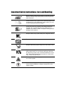
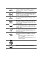
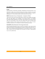
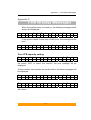
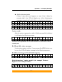
1
SA-3187S User Manual 42-30000-5138 eSATA (1.5Gb) to Serial ATA Disk Array System User Manual Version 1.1 SA-3187S eSATA (1.5Gb) to serial ATA Disk Array System User Manual Important Safety Instructions, Care and Handling Before starting, take a few minutes to read this manual. Read all of these instructions and save this manual for later reference. Protect the disk array system from extremely high or low temperatures. Let the disk array system warm (or cool) to room temperature before using it. Protect the disk array system from being bumped or dropped. Do not place the disk array system on an unstable cart, stand, or table. It may fall, causing serious damage to the product. Keep the disk array system away from magnetic forces. Do not use the disk array system near water. Keep the disk array system away from dust, sand, or dirt. Gaps and openings in the cabinet are provided for ventilation. Never block or cover these openings, because the disk array system may overheat and become unreliable. Don’t place the disk array system on a bed, sofa, rug, or other similar surface. Do not place the disk array system near or over a radiator or heat register. V Refer to the rating plate for the correct voltage and ensure that the appliance voltage corresponds to the supply voltage. The appliance must be grounded. The disk array system is equipped with a 3-wire grounded type of power cord. This power cord will only fit into a grounded type of power outlet. If an extension cord or a power center is used with the disk array system, make sure that the total current consumption of all products plugged into the wall outlet does not exceed the ampere rating. Do not place the disk array system where the cord will be walked on. Never push any kind of object into the disk array system through cabinet gaps and openings, since they may touch dangerous voltage points and cause a risk of fire or electric shock. Unplug the power cord from the wall outlet before cleaning. Keep the disk array system dry. Do not use liquid cleaners, aerosol cleaners, or a wet cloth. Use a damp cloth for cleaning. Except as specifically explained in this User Manual, do not attempt to service the disk array system by yourself. Opening or removing the covers may expose you to dangerous voltages. Unplug this product from the wall outlet and refer servicing to qualified service personnel under the following conditions. • If the disk array system has been exposed to water or any liquid. • If the disk array system has been dropped or the cabinet damaged. User should not remove the cover. Disconnect all power supply cords before servicing. Preface P Prre effa ac ce e Notice Product features and specifications described in this manual are subject to change without notice. The manufacturer shall not be liable for any damage, or for the loss of information resulting from the performance or use of the information contained herein. Trademarks This manual has been checked for accuracy, but no guarantee is given that the contents are correct. Information and specifications can change without notice. MaxTronic is not responsible for data loss or other consequences caused by the use of this manual. © Copyright 2007 MaxTronic International Co., Ltd. All rights reserved. This manual is protected by copyright and is distributed under a license restricting it’s use, copying, and distribution. No part of this documentation may be reproduced in any form by any means without prior written authorization of MaxTronic International Co., Ltd. and its licensors, if any Before starting any kind of hardware installation, please ensure that all power switches have been turned off and all power cords disconnected to prevent personal injury and damage to the hardware. -1- User’s Manual Regulatory information For Europe This equipment is in conformity with the EMC directive. Federal Communications Commission (FCC) Statement This equipment has been tested and found to comply with the limits for a Class B digital device, pursuant to part 15 of the FCC Rules. Those limits are designed to provide reasonable protection against harmful interference in a residential installation. This equipment generates, uses and can radiate radio frequency energy and, if not installed and used in accordance with the instructions, may cause harmful interference to radio communications. However, there is no guarantee that interference will not occur in a particular installation. If this equipment does cause harmful interference to radio or television reception, which can be determined by turning the equipment off and on, the user is encouraged to try to correct the interference by one or more of the following measures: Reorient or relocate the receiving antennas. Increase the separation between the equipment and receiver. Connect the equipment into an outlet on a circlet different from that to which the receiver is connected. Consult the dealer or an experienced radio/TV technician for help. Warning: A shielded-type power cord is required in order to meet FCC emission limits and also to prevent interference to the nearby radio and television reception. It is essential that only the supplied power cord be used. Use only shielded cables to connect I/O devices to this equipment. You are cautioned that changes or modifications not expressly approved by the party responsible for compliance could void your authority to operate the equipment. -2- Preface UL Listed This equipment meets UL's safety requirements. -3- User’s Manual About this manual Intended user This manual is designed and written for users of the subsystem. This is an entry level product suitable for most users. Organization of the manual This manual consists of the following sections: Chapter 1: Introduction provides an overview of the as well as details of key features and a list of specifications. Chapter 2: Before you begin provides a detailed illustrated package list. This chapter also contains all the information you need to decide whether to set up a RAID 0, 0+1, 5 or RAID 5+spare array and lists important pre-installation notices. Chapter 3: Setting up the subsystem gives a detailed overview of the subsystem’s features and guides you through the process of installing hard disk drives into. Chapter 4: Setting up an array explains how to set the RAID level, create an array and connect to a host computer. Chapter 5: Partitioning the array tells you how partition the array in Windows, Linux or Mac OS X operating systems. Appendix A: FAQ helps you deal with encountered problems in the form of Q&A. Appendix B: Glossary defines relevant technical terms used in this manual. Appendix C: LCD Display Messages lists all status and error messages that may be displayed on built-in display. Appendix D: Updating Firmware explains how to install new or updated firmware on. -4- Preface Using this manual This guide contains all the information you need to set up and start using your subsystem and to monitor its performance in real time. The setup process will follow these steps: Prepare: Familiarize yourself with the features and capabilities of (Chapter 1) Decide whether to set up a RAID 0, 0+1, 5 or 5+spare array (Chapter 2) Set up: Install drives in (Chapter 3) Set the RAID level (Chapter 4) Create: Create a RAID array and connect it to a host computer (Chapter 4) Partition: Partition the array using the host operating system (Chapter 5) -5- User’s Manual Guide to Conventions Important information that users should be aware of is indicated with the following icons: This icon indicates the existence of a potential hazard that could result in personal injury, damage to your equipment or loss of data if the safety instruction is not observed. This icon indicates useful tips on getting the most from you subsystem. Important terms, commands and programs are put in Boldface font. Screen text is given in screen font. -6- Contents T Ta ab blle eo off C Co on ntte en ntts s P P R E F A C E PR RE EF FA AC CE E.................................................................................................. 1 NOTICE ................................................................................................................................... 1 REGULATORY INFORMATION .................................................................................................. 2 Intended user................................................................................................................... 4 Organization of the manual ............................................................................................ 4 USING THIS MANUAL ............................................................................................................... 5 GUIDE TO CONVENTIONS ........................................................................................................ 6 T T A B L E O F C O N T E N T S TA AB BL LE EO OF FC CO ON NT TE EN NT TS S ........................................................................... I CHAPTER 1 .............................................................................................. 1 IIIN N T R O D U C T O N NT TR RO OD DU UC CT TIIIO ON N .................................................................................. 1-1 OVERVIEW ...........................................................................................................................1-1 KEY FEATURES.....................................................................................................................1-2 Hot Spare .....................................................................................................................1-2 Automatic drive rebuilding ..........................................................................................1-2 Hard drive hot swapping..............................................................................................1-2 SPECIFICATIONS ...................................................................................................................1-4 Available host intefaces and transfer speeds ...............................................................1-4 Disk Interface Support .................................................................................................1-4 RAID Function Support ...............................................................................................1-4 Subsystem Function Support........................................................................................1-4 Mechanical, Environmental and Safety Specifications ................................................1-5 Dimensions: 286.5(L) x152.8(W) x 206.4(H) (mm)......................................................1-5 CHAPTER 2 ........................................................................................... 2-1 B B E F O R E Y O U B E G N BE EF FO OR RE EY YO OU UB BE EG GIIIN N .......................................................................... 2-1 MAKING SURE YOU HAVE EVERYTHING ...............................................................................2-1 What's in the box..........................................................................................................2-1 What else you need.......................................................................................................2-2 PRE-INSTALLATION PLANNING .............................................................................................2-3 Introduction to RAID levels .........................................................................................2-3 RAID 0 .........................................................................................................................2-3 RAID 0+1.....................................................................................................................2-5 RAID 5 and RAID 5+hot spare....................................................................................2-6 PRE-INSTALLATION NOTICES................................................................................................2-9 CHAPTER 3 ........................................................................................... 3-1 S S E T T N G U P T H E S U B S Y S T E M SE ET TT TIIIN NG GU UP PT TH HE ES SU UB BS SY YS ST TE EM M ........................................................ 3-1 FAMILIARIZING YOURSELF WITH ..........................................................................................3-1 Overview ......................................................................................................................3-1 Front view ....................................................................................................................3-2 Rear view .....................................................................................................................3-3 LOADING DRIVES INTO .........................................................................................................3-4 CHAPTER 4 ........................................................................................... 4-1 S S E T T N G U P A N A R R A Y SE ET TT TIIIN NG GU UP PA AN NA AR RR RA AY Y ..................................................................... 4-1 ARRAY CREATION FLOWCHART ...........................................................................................4-1 -i- User’s Manual SETTING RAID LEVEL ......................................................................................................... 4-2 Setting RAID 0............................................................................................................. 4-4 Setting RAID 0+1........................................................................................................ 4-4 Setting RAID 5............................................................................................................. 4-4 Setting RAID 5+spare ................................................................................................. 4-4 CREATING AN ARRAY .......................................................................................................... 4-5 Over 2TB capacity....................................................................................................... 4-6 CHECKING THE STATUS OF SUBSYSTEM ............................................................................... 4-7 REMOVING / REPLACING A DRIVE ........................................................................................ 4-8 What if a disk fails?..................................................................................................... 4-8 Swapping drives .......................................................................................................... 4-8 Removing a drive......................................................................................................... 4-9 CONNECTING TO A HOST COMPUTER ................................................................................. 4-10 SETTING THE DISPLAY TIME & DATE................................................................................ 4-11 CHAPTER 5 ........................................................................................... 5-1 P P A R T T O N N G T H E A R R A Y PA AR RT TIIIT TIIIO ON NIIIN NG GT TH HE EA AR RR RA AY Y ............................................................ 5-1 PARTITIONING THE ARRAY - WINDOWS ............................................................................... 5-1 PARTITIONING THE ARRAY - LINUX ..................................................................................... 5-3 PARTITIONING THE ARRAY – MAC OS X ............................................................................. 5-5 PARTITIONING THE ARRAY – VISTA .................................................................................... 5-8 APPENDIX A .........................................................................................A-1 F F A Q FA AQ Q ...............................................................................................A-1 APPENDIX B .........................................................................................B-1 G G L O S S A R Y GL LO OS SS SA AR RY Y ............................................................................................B-1 APPENDIX C .........................................................................................C-1 L L C D D S P L A Y M E S S A G E S LC CD DD DIIIS SP PL LA AY YM ME ES SS SA AG GE ES S .................................................................C-1 Over 2TB capacity setting ...........................................................................................C-1 RAID initialization ......................................................................................................C-2 System ready................................................................................................................C-3 RAID and disk status messages ...................................................................................C-3 RAID level Setting and Total RAID Capacity: ............................................................C-3 Disk information: Vendor, model # (for example: Western Digital Caviar 7200rpm 120G) .....................................................................................................................................C-3 Disk information: mode, Capacity ..............................................................................C-4 Error and failure messages .........................................................................................C-4 Where the speed of failed fan is 100 rpm ....................................................................C-7 Disk rebuilding messages............................................................................................C-7 Time setting .................................................................................................................C-8 APPENDIX D........................................................................................ D-1 U U P D A T N G F R M W A R E UP PD DA AT TIIIN NG GF FIIIR RM MW WA AR RE E .................................................................... D-1 - ii - Chapter 1 – Introduction Chapter 1 IIn nttrro od du uc cttiio on n This chapter introduces the features and capabilities of subsystem. You will find: Ö A full introduction to your subsystem Ö Details of key features Ö A list of the product specifications Overview Congratulations on your selection of the subsystem. The subsystem is a high-performance and extremely flexible RAID subsystem. RAID (Redundant Array of Independent/Inexpensive Disks) is a storage technology used to improve the processing capabilities of a storage system, providing a combination of reliability and performance. This is ideally suited for integration with databases, e-mail, web servers and imaging systems. This is the ultimate approach to a flexible RAID solution. It can manage three different RAID levels (0, 0+1 and 5) and also offers the option of RAID 5+hot spare. You will find detailed explanation on the features and suggested uses of these RAID levels later in this chapter. The subsystem features a user-friendly drive carrier design that lets you easily install four drives. Each drive carrier supports a one-inch high 3.5-inch form factor drive. Featuring intelligent online recovery, the lets you hot swap a failed drive: data will automatically be rebuilt to the new drive without any system down time. The four drive design allows also one drive to be designated a hot spare: if one of other drives fails, the will seamlessly rebuild the failed drive’s data on the hot spare. - 1-1 - User’s Manual Key features The subsystem supports the following features z Automatic on-line rebuilding z Drives are hot swappable z Supports RAID levels 0, 0+1 and 5 z Optional hot spare setup for RAID 5 (5+spare) z Hot swappable fan z Supports four Serial ATA hard drives z Requires no driver z Audible alarm on drive failure & alarm mute function z Supports multiple host interfaces z Disk auto shutdown when system over heat for protecting. z Plug and play Hot Spare Hot Spare allows for the automatic replacement of a failed drive without requiring intervention from the administrator. If this option is selected and a drive fails, the will automatically replace the faulty drive with the hot spare drive. Automatic drive rebuilding If a member drive in a RAID 5 array is replaced on-line, the controller will automatically start to rebuild data to the new drive. Hard drive hot swapping Hot swapping allows for the removal and installation of disk drives without the need to power down the system while the system is in use. Auto disk shut down when over heat The will shut down disks automatically when temperature is over 55 oC to prevent the damage of DISK and DATA loss. - 1-2 - Chapter 1 – Introduction This manual contains the information necessary to set up each of the two available hardware configurations of the subsystem . Where procedures for the configurations differ, they are described separately and clearly marked. - 1-3 - User’s Manual Specifications Available host intefaces and transfer speeds z eSATA 1.5Gb Disk Interface Support z Four SATA1 1.5Gb disk interfaces and compatible with SATA2 3Gb disks RAID Function Support z Hardware RAID level 0, 5, 0+1, 5 + spare by switch setting z Hot swappable disk z Automatic on-line rebuilding Subsystem Function Support z Driverless z Plug & Play z Multiple operating system support: Mac OS 9 / X (10.2.8 & 10.3) Windows NT4.0/2000/2003/XP Linux 9.0 Fedora z GUI support for system status monitoring z Support over 2TB RAID capacity z On board 2MB buffer cache size z LCD panel for operation status display z Event notification through audible alarm or e-mail z Alarm mute switch z Memory for RAID level status z One RS-232 port for terminal or GUI connection z Removable cooling fan module - 1-4 - Chapter 1 – Introduction Mechanical, Environmental and Safety Specifications Dimensions: 286.5(L) x152.8(W) x 206.4(H) (mm) z Host Connectors (depending on hardware configuration): z One eSATA connector Interface Connectors: One RS-232 connector z Operation temperature: 0 ~ 35℃ z Operation humidity: 5 ~ 95 %, non-condensing z Storage humidity: 5%~95%, non-condensing z 200 W power supply 100~264V(+/-10%),47~63Hz Output +5V/10 A, +12V/10 A, +3.3V/5A Specifications are subject to change without notice. - 1-5 - Chapter 2 – Before you begin Chapter 2 B Be effo orre ey yo ou ub be eg giin n This chapter includes all the information you need to prepare for installation and to decide which RAID level to use. You will find: Ö A checklist of what should be in the product package Ö A full introduction to and comparison of RAID levels 0, 0+1 and 5 Ö Ö Important notices on the safe operation and installation of Making sure you have everything What's in the box Some vendors may ship certain components as standard, while other vendors treat the same component as optional. In its most basic configuration, your package should include the following: z The subsystem with four drive trays (Disk not included) - 2-1 - User’s Manual z The following cables: Power cable z Screws pack z Drive lock keys (x2) z User Manual eSATA cable What else you need In order to setup a working system, the following user-supplied items are required: z Host computer system with eSATA interface z Four disk drives For non-proprietary accessories, such as cables, etc., ask your vendor to recommend compatible and reliable brands. - 2-2 - Chapter 2 – Before you begin Pre-installation planning Introduction to RAID levels The can support the following RAID levels: 0, 0+1 and 5 with the additional option of RAID 5 + hot spare. Which is the right level for you? The answer depends on the application it is used for. RAID Level 0 offers high transfer rates, and is ideal for large blocks of data where speed is of importance. Computer Aided Design, Graphics, Scientific Computing, Image and Multimedia applications are all good examples. If one drive in a RAID 0 array fails however, the data on the whole array is lost. RAID Level 0+1 combines mirroring and striping functions on a minimum of four hard disks. Mirroring provides full redundancy and protects data in case of multiple drive failure (providing that data on one of each mirrored pair of drives is intact). RAID Level 5 arrays offer high I/O transaction rates, and are the ideal choice when used with on-line transaction processing applications, such as those used in banks, insurance companies, hospitals, and all manner of office environments. These applications typically perform large numbers of concurrent requests, each of which makes a small number of disk accesses. If one drive in a RAID 5 array fails, the lost data can be rebuilt from data on the functioning disks. The allows users to set one disk as a hot spare that will be activated automatically to replace a failed disk. RAID 0 RAID 0 links each drive in the array as one huge drive. Storage capacity is determined by the smallest drive in the array. That capacity is then applied to format all other drives in the array. If using a 40 GB, 50GB, 60 GB, and 70 GB drive in a RAID 0 array, your system will see one huge drive of 160 GB (40 GB×4). RAID 0 offers double or more performance under sustained data transfers when one drive per ATA port is used. In such a configuration, unlike SCSI, ATA drives are always available to the system. SCSI requires more management of the SCSI bus. But RAID 0 without fault tolerance, if one of disks in RAID 0 array group fails, the RAID crashed. - 2-3 - User’s Manual RAID 0: Striped disk array without fault tolerance Characteristics: Recommended use: RAID 0 implements a striped disk array, the data is broken down into blocks and each block is written to a separate disk drive. I/O performance is greatly improved by spreading the I/O load across many channels and drives. Fastest and most efficient array type but offers no fault-tolerance. Storage capacity = (No. of disks) × (capacity of smallest disk) If installed 40 GB, 50 GB, 60 GB and 70 GB, configured as RAID 0, the RAID capacity will be 160 GB. Video production and editing Image editing Pre-press applications Any application requiring high bandwidth The diagram below represents the writing of data on a RAID 0 array composed of four DISKS connected to the controller. Data blocks are distributed across all disks in the array. Arrangement of data blocks saved on a Level 0 RAID - 2-4 - Chapter 2 – Before you begin RAID 0+1 RAID 0+1 combines mirroring and striping functions on a minimum of four hard disks. Mirroring provides full redundancy and protects data in case of multiple drive failure (providing that data on one of each mirrored pair of drives is intact). RAID 0+1: Combination of mirroring and striping Characteristics: This configuration provides optimal speed and reliability. Requires even number of disks (minimum 4 disks) Storage capacity = 2 x capacity of smallest of disk If installed four drives each are 40 GB, 50 GB, 60 GB and 70 GB, configured as RAID 0+1, the RAID capacity will be 80 GB. The diagram below represents the writing of data on a RAID 0+1 array composed of four DISKS connected to the controller. The controller creates two matching RAID 0 arrays on four DISKS. Arrangement of data blocks saved on a Level 0+1 array - 2-5 - User’s Manual RAID 5 and RAID 5+hot spare RAID 5 uses a mathematical expression that compares data from three drives and calculates a fourth piece of data called “parity” which is saved on a fourth drive. Should one of the drives fail, parity data can be used to rebuild the failed data. Under RAID 5, parity data is stored across all drives in the array. This maximizes the amount of storage capacity available from all drives in the array while still providing data redundancy. RAID 5 requires at least three drives. The allows users to set RAID 5 with three drives and the fourth drive as a “hot spare” ready to be used for rebuilding data in case one of the other drives fails. This is RAID 5 +hot spare function. RAID 5: Independent data disks with distributed parity blocks Characteristics: Recommended use: Each entire data block is written on a data disk. Parity for blocks in the same rank is generated on Writes, recorded in a distributed location and checked on Reads. Highest Read data transaction, medium Write data transaction rate. Relatively low ratio of ECC (Parity) disks to data disks means high efficiency (compared to other RAID levels). Good aggregate transfer rate. Storage capacity = (No. of disks – 1) × (capacity of smallest disk) In RAID 5, installed drives each are 40 GB, 50 GB, 60 GB, 70 GB, the RAID capacity will be 120 GB. In RAID 5 + hot spare, installed 40 GB, 50 GB, 60 GB each in disk 2, 3, 4 and installed 70 GB in disk 1 as hot spare disk, the RAID capacity will be 80 GB. - 2-6 - File and application servers Database servers WWW, E-mail and News servers Intranet servers Most versatile Raid level Chapter 2 – Before you begin The diagram below represents the writing of data on a RAID 5 array composed of four DISKS connected to the controller. Parity blocks are represented by the letter P. - 2-7 - User’s Manual The diagram below represents the writing of data on a RAID 5+hot spare array composed of four DISKS connected to the controller. Parity blocks are represented by the letter P. Arrangement of data and parity blocks saved on a Level 5+hot spare RAID - 2-8 - Chapter 2 – Before you begin Pre-installation notices Before starting any kind of hardware installation, please ensure that all power switches have been turned off and all power cords disconnected to prevent personal injury and damage to the hardware. To avoid overheating, should be installed in a well-ventilated area and in such a way that sufficient airflow is maintained across the controller chips. Static electricity can damage electronic components. To guard against such damage: Work in a static-free environment Wear a grounded anti-static wrist strap Store uninstalled components in anti-static bags Handle PCBs by their edges and avoid touching chips and connectors. Environmental requirements: Temperature: 0-35C Operation humidity: 5-95%, non-condensing Storage humidity: 5-95%, non-condensing - 2-9 - Chapter 3 – Setting up the subsystem Chapter 3 S Se ettttiin ng gu up p tth he es su ub bs sy ys stte em m This chapter gives an overview of the subsystem and explains how to: Ö Remove the drive carriers from the subsystem Ö Load hard drives into the drive carriers Ö Install the drive carriers in subsystem Familiarizing yourself with This manual contains the information necessary to set up the available hardware configurations. Where procedures for the configurations differ, they are described separately and clearly marked. Overview The subsystem has four drive carriers, accessed from the front. The connectors and power switch are located on the rear panel. - 3-1 - User’s Manual Front view Drive carriers Each drive carrier can hold a one-inch high 3.5-inch form factor SATA disk drive. LCD Display The LCD displays status and configuration information for the subsystem and arrays. A full list of LCD display messages is given in Appendix C. Scroll button The scroll button is used to scroll through information on the display and to select settings for the date and time. Enter / Mute button The Enter / Mute button is used to set date, time and to mute the buzzer. - 3-2 - Chapter 3 – Setting up the subsystem Rear view Power switch The power switch is the main on/off switch of the subsystem. Fan vent The fan vent should be kept unobstructed. RAID level selector The RAID level selector consists of two switches which together are used to set the RAID level. See Setting RAID level in Chapter 4. eSATA port The eSATA port is used to connect your subsystem to host computer. AC power connector To connect to AC power code. RS232 port The RS232 port is used for data transmission for firmware update and GUI interface. - 3-3 - User’s Manual Loading drives into The subsystem should be fitted with four hard disk drives. Load each drive into a drive carrier as follows: 1. Pull the drive carrier handle to release the latch. 2. Slide the drive carrier out of the subsystem. 3. Place the disk drive in the drive carrier and secure the disk in the carrier 4. Slide the loaded disk drive carrier into the subsystem and push flat the carrier handle to lock the carrier in position. - 3-4 - Chapter 4 – Setting up an array Chapter 4 S Se ettttiin ng gu up pa an na arrrra ay y This chapter explains how to: Ö Set RAID level Ö Create an array Ö Remove and replace drives from an array Ö Connect subsystem to a host computer Ö Set the time and date Array creation flowchart Setting up an array is simple. This chapter will lead you through the following steps: Set RAID level z Use the RAID level selector to set the RAID level (0, 0+1, 5 or 5+spare) Create array z Load four drives into subsystem,,then turn on to create array. Replace any faulty drives. Connect to the host computer z When RAID initialization is complete, connect your subsystem to a host computer. z Set the time and date on the subsystem display. Set time & date - 4-1 - User’s Manual Setting RAID level RAID level is set using the RAID level selector on the rear panel of the subsystem. The RAID level selector consists of two switches. The four possible combinations of switch position correspond to the four available RAID settings: 0, 0+1, 5 and 5+spare. If the RAID level is not matched between the disk setting and the RAID level selector setting, the LCD will display the following two messages alternatively: (1) “RAID level” “Unmatched” (2) “Current: Rx” “Original: Rx” Note: Current Rx means the RAID level setting of RAID level selector Original Rx means the RAID level setting of current disks For example: Supposed the RAID level selector is R0, but the disk setting detected from disks is R5, the LCD will display the following two messages alternatively: (1) "RAID Level" "Unmatched” (2) "Current : R0" "Original : R5" Solution:At this situation, RAID cannot work, users should choose one of the following options : (1) Shut down and tune the RAID level selectors to R5. OR (2) Re-plug the four disks and re-create the Array to R0 (But data in the R5 disks will be lost due to the destructive initialization) - 4-2 - Chapter 4 – Setting up an array The subsystem must be switched off to change RAID level. To change RAID level: 1. Power off 2. Set the new RAID level using the RAID level selector 3. Remove all four disks 4. Power on 5. Install the four disks to start RAID initialization Changing RAID level may lead to the loss of all data on the array. - 4-3 - User’s Manual Setting RAID 0 1. Ensure is turned off. 2. Move both selector switches 1 and 2 to ON as shown. Setting RAID 0+1 1. Ensure is turned off. 2. Move selector switch 1 to ON and 2 to OFF as shown Setting RAID 5 1. Ensure is turned off . 2. Move both selector switch 1 and 2 to OFF. Setting RAID 5+spare 1. Ensure is turned off. 2. Move selector switch 1 to OFF and 2 to ON. Initially, in a RAID 5+spare array, the drive in the TOP drive carrier is the hot spare and its status indicator will be shown amber for notification. In a RAID 0+1 array, disk 1 , 2 and disk 3 , 4 are two independent RAID 1group . This allows one disk from each separate R1 group to fail simultaneously. - 4-4 - Chapter 4 – Setting up an array Creating an array To create (initialize) an array: 1. Ensure that the RAID level selectors are correctly positioned for the desired RAID level. 2. Connect a power cable. 3. Turn on the power switch. 4. Install drives to begin initialization The subsystem will check the status of the installed drives. If all of four drives are brand new or never been used in same kinds of subsystem, then the initialization of the desired RAID level array will begin automatically. If any one of disks you installed has been used in before, then the subsystem will have a notification on LCD to remind if you really want to initialize a new RAID with previously used DISK to prevent wrong operation caused DATA loss. The subsystem confirms with you that “Create New RAID” and you can select “Yes” by button to re-create new RAID or “No” to retrieve existing RAID according to current drives Four drives should usually be installed for initialization to begin. If four drives are not installed when the power is turned on, the alarm will sound. A “RAID Fail” message will also display unless: RAID 5+hot spare has been set The bottom three drive carriers have drives installed. In this case, the initialization of a RAID 5 array will take place. - 4-5 - User’s Manual The RAID capacity determined on the RAID level and the capacity of drives you installed in , for an example: If configuring as R5 and install 4 drives each of them are 10 GB, 20 GB, 30 GB, 40 GB to create an array then the total RAID capacity will be 30 GB. If a red disk status indicator shows, check to make sure the appropriate drive is: z Locked z Installed correctly z Not faulty (if necessary, the drive should be replaced). The alarm will sound in case of RAID failure. Press the Enter / Mute button to the right of the display to silence the alarm. Over 2TB capacity The subsystem supports over 2TB capacity. If your operation system (e.g. Windows Vista) that supports a SATA device with over 2TB capacity. After create the array, you can have the setting to enable over 2TB capacity by the scroll button. The below steps will guide you to enable over 2TB capacity. 1. Create a new RAID. 2. Select scroll button to find the capacity setting item「Enable over 2T」on LCD panel. Press ENT button to continue. 3. Select YES to enable over 2TB capacity. The device over 2TB capacity should be supported by Operation System (e.g. Windows Vista). Please refer to Chapter 5. Partitioning the array with over 2TB capacity to partition the device. - 4-6 - Chapter 4 – Setting up an array If system power is turned off midway through array initialization, the process will continue from its point of interruption when power returns. Checking the status of subsystem The status of the subsystem and array is given by the LCD display. Press the scroll button to the left of the display to scroll through information about the array. The following information is available: Ö RAID level and Capacity Ö Disk model Ö Disk DMA mode and capacity Ö Firmware Version Ö Serial Number Ö Fan Status and Temperature Status A full list of LCD display messages is given in Appendix C - 4-7 - User’s Manual Removing / replacing a drive What if a disk fails? If a disk drive fails, the disk status indicator of the disk carrier will light red and the alarm will sound. When this happens, you should replace the failed disk. The failure or removal of a single drive in a RAID5 array will not lead to failure of the array. The failure or removal of a single drive in a RAID0 array will lead to loss of all data on the array and the entire array must be re-initialized. There is no need to immediately replace a failed disk in a RAID 5+spare array. The hot spare disk will be brought on line automatically. The alarm can be silenced by pressing the Enter / Mute button to the right of the display. Swapping drives The hot swap function for RAID 5 arrays enables failed disks to be swapped while the array is powered on. RAID rebuilding will be processed automatically in the background and the RAID subsystem will record its progress. If the host system is shut down or powered off abnormally, the RAID subsystem will continue the disk rebuilding process after power is turned on again. A hard disk in a RAID 5 array should not be replaced when the system is turned off. Doing so may leads to loss of data. Always hot swap disks in a RAID5 array when the system is turned on. - 4-8 - Chapter 4 – Setting up an array Removing a drive 1. Pull the drive carrier handle. 2. Slide the drive carrier out of the subsystem. 3. Remove four screws from the tray and lift out the disk drive. - 4-9 - User’s Manual Connecting to a host computer Once the array is initialized, you can connect subsystem to a host computer. The RAID cannot be recognized by Operating System before initialization complete. To connect to the host: 1. Power on subsystem and follow the instructions earlier in this chapter to establish a RAID array. 2. Either: Ö Connect one end of the supplied eSATA cable to the eSATA port and the other end to a spare eSATA port on your host computer. Advanced users wishing to remotely monitor the status of their array should connect subsystem via an RS-232 cable to a terminal or computer hosting a terminal emulation program. 3. The host computer should detect the presence of the subsystem. Turn to the next chapter for instructions on formatting your array. - 4-10 - Chapter 4 – Setting up an array Setting the Display Time & Date Press down the right hand (Enter) button for over five seconds to enter or change the time and date displayed on the display. When you release the button, the date and time setting screen will show: 1. First enter the year. Change the displayed value by pressing the left hand (Scroll) button. When the correct value is displayed, press the Enter button to move to the next field. 2. Enter the month in the same way then move to and enter the date. 3. Press the Enter button to move to the hour filed. Enter the time in the 24-hour clock format. 4. Press Enter when you have entered the correct minute value to complete time and date entry. - 4-11 - YY/MM/DD HH:MM 03/11/23 19:27 Chapter 5 – Partitioning the array Chapter 5 P Pa arrttiittiio on niin ng g tth he ea arrrra ay y This chapter explains how to partition the array in Windows , Linux and Mac OS X operating systems. Partitioning the array - Windows The array must be partitioned before it can be used. To do this on a Windows operating system: 1. Establish the array and connect to the host computer following the instructions in the preceding chapter. Make sure no error messages are showing on the LCD display. 2. Turn on the host computer. 3. On the desktop, right click the My Computer icon. 4. Select Manage. The Computer Management dialog box appears. 5. In the Computer Management dialog box, select Disk Management from the left hand menu. The array will appear in the lower right section of the dialog box as a disk marked unallocated. Other disks attached to the host machine, such as the main drive of the machine, will have an assigned letter (e.g. C:) for the parts of the disk (partitions) that are accessible to the operating system. These are listed in the upper right part of the dialog box. You must partition the disk and make it accessible to the operating system. - 5-1 - User’s Manual 6. Right click on the disk representing the array and select Create Partition. Follow the wizard to create one or more partitions on the array. 7. When you have completed creating a partition, the array will appear as a disk in the disk management section of the Computer Management dialog box. - 5-2 - Chapter 5 – Partitioning the array Partitioning the array - Linux The array must be partitioned before it can be used. To do this on a Linux operating system: 1. Establish the array and connect to the host computer following the instructions in the preceding chapter. Make sure no error messages are showing on the LCD display. 2. Turn on the host computer. 3. Check to confirm the operating system has detected the array: type “df” The array will be listed as shown at a temporary location (/tmp). The code given the array depends on the host interface type. Arrays connected through a USB or IEEE 1394 interface will be assigned a code sda (sdb, sdc etc.). Arrays connected through a serial ATA interface will be assigned a code hde (hdf, hdg etc.) as in the example shown. When you have confirmed that the array has been detected: 4. Enter the command to format the disk (array): fdisk /directory/device name (e.g. fdisk /dev/hde). 5. When the disk is formatted, you should partition the disk. Call up the help screen as shown to identify the correct command to add a partition. - 5-3 - User’s Manual 6. Enter the command to add a partition (in the example given, the command is “n.”) 7. Enter the command to create a primary partition then enter the number of primary partitions you wish to create. 8. Enter the command to create a Linux second extended file system on the array. In the example, the command is mke2fs /directory/device (mke2fs /dev/hde). 9. Assign the array a location: Enter mount /directory/device /location (mount /dev/hde /tmp). - 5-4 - Chapter 5 – Partitioning the array Partitioning the array – Mac OS X The array must be partitioned before it can be used. To do this on a Mac operating system: 1. Establish the array and connect to the host computer following the instructions in the preceding chapter. Make sure no error messages are showing on the LCD display. 2. Turn on the host computer. 3. When the array is detected by system, it will be shown as an untitled device on desktop. 4. Executing Disk utility to begin partitioning array, (Disk utility is located Applications/Utilities). The Disk utility dialog box appears, and the array will appear in the left menu of window as an untitled disk. Other disks attached to the host machine, such as main drive of the machine, will have an assigned name for the parts of the disk (partition) that are accessible to the operating system. These are listed in the left hand menu of dialog box. You must partition the disk and make it accessible to the operating system. 5. Choosing by click in left menu and click on tag “partition” to fill the name and size of the array. The array could be created to be a single volume or several volumes, determined by intention of user. Then click Partition, which located lower right corner of dialog box. - 5-5 - User’s Manual 6. The confirmation dialog will be pop out to confirm again. Click Partition to continue procedure. 7. The partition will then begin, and process is been showing as creating partition map in lower right corner of dialog box. 8. When you have completed creating a partition, the array will appear as a disk in storage list in left menu, and be put on desktop as shortcut. - 5-6 - Chapter 5 – Partitioning the array - 5-7 - User’s Manual Partitioning the array – Vista The array must be partitioned before it can be used. To do this on a Windows Vista operating system: 1. Right click Computer and click Manage. 2. From the Computer Management window, select Disk Management. 3. Windows operation system will list all the hard drives that are installed on the system. Locate the subsystem drive that is represented by the icon. Right click the icon and select Initialize Disk. 4. The Initialize Disk dialog box will appear, select the disk number and select the MBR (Master Boot Record) partition style. Click OK to partition. If over 2TB capacity is needed, please choose GPT (GUID Partition Table) to partition. 5. In the drive box to the right shows Unallocated, right click and select New Simple Volume. 6. The New Simple Volume Wizard dialog box will appear, click Next to continue. 7. After selecting the partition type, specify the partition size, and assign a drive letter, the Format Partition dialog box will appear. In addition to regular formatting, you can also choose Quick Format, which allows faster formatting by skipping the scan of all disk sectors. Click Next to start the format process. - 5-8 - Chapter 5 – Partitioning the array 8. Your drive should now appear in your Computer and ready for use. - 5-9 - Appendix A – FAQ Appendix A F FA AQ Q If you encounter a problem while using the subsystem, check this section for help. 1. My Operating System is Linux. I have enabled the over 2TB capacity setting, but I still cannot partition a device over 2TB in OS. Why? Ö The subsystem is over 2TB available, but most OS still cannot support SATA device to over 2TB capacity. Please refer to the below list for choosing the OS. a) Microsoft Windows Vista 2. I have connected the subsystem, but it does not appear in the motherboard BIOS. Why? Ö Ensure that an array is initialized completely. 3. How should I react to disk failure? Ö For a RAID 5/RAID 0+1 array, you should replace the failed disk. Data rebuilding will then begin. Ö For a RAID 5+hot spare array, data will be rebuilt automatically to the hot spare disk. There is no need to immediately replace the failed drive. Ö The capacity of new DISK you installed must equal or larger than the smallest disk in the subsystem. Otherwise, it will be rejected by the subsystem, though it has no any damage. 4. How should I react to a disk failure while creating a RAID 5? Ö Replace the failed DISK with another of equal or larger capacity. The array will re-initialize from starting. 5. If I only have two or three disks, can I create a RAID? Ö 2 disks: No. need at least 3 disks to configure R5+hot spare Ö 3 disks: Yes, but you can only choose R5+hot spare. The three disks must be installed in the bottom three disk carriers with the top layer – the hot spare location, left empty. 6. Why does the display read “unmatched”? Ö The RAID level selector is not set to the level of the existing array. Please choose one of the following options : Supposed the RAID level selector is R0, but the disk setting detected from disks is R5. (1) Shut down and tune the RAID level selector to R5. - A-1- User’s Manual or (2) Re-plug the four disks and re-create the Array to R0 (But data in the R5 disks will be lost due to the destructive init ) 7. If I really want to re-create a new RAID. How should I do? Ö Remove all disks. Ö Power off the subsystem, set up RAID level by selector switch than power on the subsystem. Ö Plug in all of disks to initialize new RAID. Ö If you use previous disks, subsystem will show a message “Create New RAID?” to confirm with you if you really want to create a new RAID. Please choose “Yes” by right button, the initialization will then begin. Ö Please notice that the procedure will erase all data of the four disks. 8. The host computer cannot detect the subsystem. What should I do? Ö Make sure the host interface connection cable is attached securely to ports on and the host and is not damaged. Ö Check the display for error messages. 9. A disk has failed. What should I do? Ö Swap the failed disk with one of the other three disks and turn on. If the same disk fails, replace the disk. If the failure reappears at the same drive carrier, either the drive carrier or subsystem is faulty. Perform the next step. Ö Swap the position of the drive carrier that failed twice and turn on. If the same drive carrier fails, replace it. If the failure reappears at the same drive carrier slot, the subsystem is faulty. Perform the next step. Ö The subsystem appears to have an internal malfunction. Consults your dealer. 10. Two disks have failed. What should I do? Ö Swap the positions of the failed disks with the remaining two disks. If the same disks fail, replace them. If the failures reappear at the same drive carriers, either the drive carriers or subsystem is faulty. Perform the next step. Ö Swap the position of the drive carriers that failed twice with the working drive carriers and turn on. If the same drive carriers fail, replace them. If the failures reappear at the same drive carrier slots, the subsystem is faulty. Perform the next step. Ö The subsystem appears to have an internal malfunction. Consult your dealer. - A-2- Appendix A – FAQ 11. Three disks have failed. What should I do? Ö Swap the single functioning disks with each of the failed disks in turn. If the functioning disk continues to function at its new location, the original disk was faulty and should be replaced. If the functioning disk does not function at any of the three other locations, the drive carriers for those location or the subsystem is faulty. Perform the next step. Ö Swap the functioning drive carrier in the same way to find out if the drive carriers or the subsystem. Replace any malfunctioning drive carriers. Ö Consult your dealer if the subsystem appears to be faulty. 12. Four disks have failed. What should I do? If four disks have failed, you will need to use another disk that you know is functioning. Use this disk in the same way as outlined in the previous answer to find out if the malfunction is with the original disks, the drive carriers or the subsystem. 13. What should I do when I see below error message on LCD? Ö Condition 1 R A I D F a i l C o d e : 0 Note: not enough number of function disks for a RAID to operate Solution: Install all of 4 disks to conform to create a new RAID. Ö Condition 2 R A I D F a i l C o d e : 1 < x x x x > Note: Represents disk sequence is wrong, and the current sequence displayed within <> Solution: Replace the sequence of disk as original. - A-3- User’s Manual Example: <2134>: disk 2 and disk 1 sequence is reversed. <13x4>: the original disk 3 is put into tray 2 and the original disk 2 is not plugged or failed. Ö Condition 3 R A I D F a i l C o d e : 2 Note: The RAID has been failed but all of 4 disks exist. Since F/W Version 1.4 or later. Solution: To create a new RAID or you should call vendor to try to save the data from system. Ö Condition 4 B a t t e r y F a i l e d Note: Battery is low, missing, or failed. Solution: Please contact with your distributor or vendor to change a new battery Ö Condition 5 F a n F a i l e d Note: Fan is low, missing, or failed. Ö Solution: Please contact with your distributor or vendor to change a new Fan. - A-4- Appendix B– Glossary Appendix B G Gllo os ss sa arry y Array See Disk Array. Array Management Software The body of software, that provides common control and management for a disk array. Array Management Software most often executes in a disk controller or intelligent host bus adapter, but may also execute in a host computer. When it executes in a disk controller or adapter, Array Management Software is often referred to as Firmware. Cache Controller memory used to speed up data transfer to and from a disk. Disk Array A collection of disks from one or more commonly accessible disk controllers, combined with a body of Array Management Software. Array Management Software controls the disks and presents them to the array operating environment as one or more virtual disks. Firmware See Array Management Software. Host Computer Any computer system to which disks are directly attached and accessible for I/O. Mainframes, and servers, as well as workstations and personal computers, can all be considered host computers in the context of this manual, as long as they have disks attached to them. - B-1- User’s Manual Parity Parity information is redundancy information calculated from actual data values. If any single piece of data is lost, the data remaining and the parity information can be used together to compute the lost data. Parity information can either be stored on a separate, dedicated drive, or be mixed with the data across all the drives in the array. RAID (Redundant Array of Independent / Inexpensive Disks) A disk array in which part of the storage capacity is used to store redundant information about user data stored on the remainder of the storage capacity. The redundant information enables regeneration of user data in the event that one of the array member disks or the access path to it fails. See Parity. Different RAID level offer different data throughput speeds and fault tolerance (data redundancy). RAID 0 does not feature redundant information but is nonetheless considered a special type of RAID. Serial ATA (Serial Advanced Technology Attachment) Serial ATA (often abbreviated as SATA or S-ATA) is an advance on the commonly used Parallel ATA interface for data storage devices. Serial ATA allows data transfer up to 1.5 Gbps. It has an additional advantage parallel ATA in that cables are thinner, so airflow within computer cases is less impeded, and can extend to one meter in length (against only 40 cm for parallel ATA). - B-2- Appendix C – LCD Display Messages Appendix C L LC CD DD Diis sp plla ay yM Me es ss sa ag ge es s When the system power is turned on, the following message will be always first displayed: e S A B T o A o t R . A . I . D If the system installs 4 disks with a RAID level, this message will be next. I n i e t S i A a T l A i z R e A I D D i s k s Over 2TB capacity setting E n a b l e o v e r 2 T P r e s s E N T s e l e c t If you would like to enable the function of support over 2TB capacity, press the button “ENT” to select this function, the next message will be displayed. At this condition user presses the scroll buttons, the below messages will be displayed: E ( n Y a E b S l ) e o v e r 2 T E n a b l e o v e r 2 T ( N O ) When use presses “ENT” after the new condition select, the subsystem will reboot. - C-1- User’s Manual RAID initialization Create new RAID When the system is powered on and it’s ready, replace 4 disks, the following message will be displayed to ask user to confirm the initialization process. C ( r N e O a ) t e N e W R ( A Y l E D S ? ) User can press the MENU or ENTER button to select NO or YES to confirm your selection and move to the next operation. RAID initialization started After select YES, system will automatically enter the RAID initialization state by showing the disk initialization progress on the LCD display. R A T I o D t a I l N : I T x x x x x x . x G % B Where xx.x % represents the percentage of RAID capacity being initialized. RAID initialization completed without error If there is no error during initialization, LCD panel will display the following message upon finish the initialization stage. R x A x I x D x I G N B I - C-2- T I N 1 I 0 T 0 % O K ! Appendix C – LCD Display Messages RAID initialization failed If there is any disk error happens on one of the 4 disks, for example disk 2, the LCD will display one of the following two messages respectively for disk failure or bad sectors detected: R D A 2 I R D A 2 I D o D B f I f N l I i T n N a I d I s T e F a i l e d F t a o i r l s e d e c System ready After the system is powered on with all 4 disks successfully initialized, it will display the following message: R e a e d S y A T A R A I h D h : m m Where hh:mm represents the hour and minutes of current time if being correctly set. RAID and disk status messages Under system ready condition, if user presses the MENU button one by one, the LCD will display message in the following sequence: RAID level Setting and Total RAID Capacity: L 1 e 2 v 0 e l G 5 B Disk information: Vendor, model # (for example: Western Digital Caviar 7200rpm 120G) D W i D S 1 k 2 0 1 0 B B - C-3- User’s Manual Disk information: mode, Capacity S 1 e 2 r 0 i a l G A B T A Repeat messages 6.2.5.1 to 6.2.5.3 until all 4 disks information being displayed System firmware version: F V i e r r m : w 1 a . r 0 e 0 System serial number: S 0 e 0 r 0 i 9 a 7 l 6 1 N 0 u 0 m 0 b 0 e 0 r 2 3 8 0 r r p e m : 4 0 。 C System fan speed and temperature: F T a e n m : p 3 e 6 r 0 a 0 t u Error and failure messages Error or failure messages will be displayed on LCD panel under the following conditions: Disk failure message: if one of the 4 disks fails in the operation D I S K x F a - C-4- i l u r e Appendix C – LCD Display Messages Disk bad sector messages D T I o S t K a x l b a b a d d : : x Y x “DISK x bad Y”: It means disk x has Y bad sector. “Total bad xx”: it means total xx bad sectors had have. If the DISK has more than 8 sector, the subsystem will beep to let the user know how bad of the drive. D B I a S d K s x e c F t a o i r l : u 1 r 0 e “DISK x Fail” “Bad sector: 10”: It means if the bad sector count of DISK has more than 10 or equal 10 sectors, the subsystem will kick the DISK out. D B I a S d K s x e F t c a o i r l : Y Y / 1 5 “DISK x Fail” “Bad sector:yy/15”: It means DISK x has Y bad sectors and the number 15 means the total remapped area. In the subsystem remap policy, when the total bad count to 15, the controller will start to compare each DISK of bad sectors count to determine which DISK has the maximum bad sectors and then the controller will kicked it out. RAID failure message: if the RAID crashes and the data cannot be recovered R C A o I d D e F 0 a i l “Code 0” represents not enough number of function disks for a RAID to operate R C A o I d D e F 1 a i < l 1 3 X 4 > “Code 1” represents the disk sequence is wrong with current sequence displayed within <>. - C-5- User’s Manual Examples: <2134>: disk 2 and disk 1 sequence is reversed. <13x4>: the original disk 3 is put into tray 2 and the original disk 2 is not plugged or failed. <423s>: the spare disk is put in the tray 4 and original disk 4 is put in the tray 1 R C A o I d D e F 2 a i l “Code 2” represents the array has been failed but of 4 disk exist. RAID configuration error message: The following two messages will be displayed alternatively when the setting of RAID level selectors does not match the existing disk RAID level setting: C O u r R U A n I m D a r i r g e i n n t L c e h v e e d t a : l R : 5 R 0 l The system will stop working until users choose one of the following options: Shut down subsystem and tune the RAID level selectors to R5 Re-plug the four disks and re-create the RAID to R0 (but data in the R5 disks will be lost) - C-6- Appendix C – LCD Display Messages Fan failure message: fan can not function normally F 1 A 0 N 0 F a r i p l m Where the speed of failed fan is 100 rpm o Overheat message: will be displayed when temperature > 50 C T O e 5 m 1 p 。 e C r a > t u 5 r 0 e 。 ! C ! Disk shut down message: will be displayed when temperature > 55 oC v e r T e m p e r a t u r e D i s k S h u t d o w n ! Disk rebuilding messages The system will display the disk rebuilding progress when a failed disk is replaced by a new one. D x T o R t e a b l u : i l x d x x x x G . B x % Where xx.x represents the percentage of RAID capacity is being rebuilt. If there is no disk error during rebuilding, the LCD panel will display the following message upon finishing the initialization stage. D x x x R x e G b B u i O l K d ! 1 0 0 % If the capacity of newly installed disk (diskx, 80GB, in the example below) is less than the minimum capacity required for rebuild, the LCD panel will display the following message. D 8 x 0 R G e B b u < i 1 - C-7- l 2 d 0 F G a B i l User’s Manual If there are too many bad sectors detected in the newly installed disk during rebuilding process, the LCD panel will display the following message. D D x x R B e a b d u i s l e d c t F o a r i s l If the newly installed disk can not be accessed (and thus fails), the LCD panel will display the following message. D D x x R O e f b f u l i i l n d e F a i l Time setting After the Enter button is pushed for over five seconds and released, the following message will be displayed for users to change the time and date. Y x Y x / / M x M x / / D x D x H x H x : : M x M x To press the MENU button to select between 0 to 9, and press the Enter button to confirm your selection and move to the next operation. Start by adjusting the year (YY), then move to the month (MM), the day (DD), and finally the hour (HH) and minute (MM) (the time is measured in the 24-hour clock format). Pressing the Enter button on the final selection will set the time and date. - C-8- Appendix D – Updating Firmware Appendix D U Up pd da attiin ng gF Fiirrm mw wa arre e The subsystem is shipped with firmware installed. You may however wish to install new or upgraded editions of the firmware. Ask your vendor about the latest firmware edition. Once new or updated firmware has been obtained, it can be downloaded to from a host PC with third party communication software, such as HyperTerminal, that supports ANSI terminal emulation. Other terminal programs may be used in place of HyperTerminal to communicate with the subsystem. However, the setup process for other terminal software may differ from that outlined in this chapter. Array data and configurations are not affected by updating of firmware. HyperTerminal is bundled as standard with Microsoft Windows operating systems. It will be found in the Communications folder. The program can also be downloaded from Hilgraeve Software at http://www.hilgraeve.com/htpe/ 1. Ensure is turned off. 2. Connect one end of the supplied RS-232 cable to the RS-232 port on the rear of subsystem and connect the other end to one of the host computer’s COM ports. - D-1- User’s Manual 3. Launch HyperTerminal from the desktop of the host computer (Start > Programs > Accessories > Communications > HyperTerminal). 4. The Connection Description dialog box will appear (if this is the first time you have run HyperTerminal, you will first be prompted to enter information about your location). Enter a name to identify the subsystem connection (e.g. ) and select an icon to represent the connection. Press OK. 5. The Connect to dialog box appears. Select COM1 or COM2 from the Connect using: dropdown menu, depending on which port is linked to . Click OK. 6. The COM Properties dialog box will appear. Set the following values: Bits per second: 19,200 19200 Data bits: 8 Parity: None Stop bits: 1 Flow Control: Xon/Xoff 7. Click OK. The HyperTerminal connection to subsystem is now established. - D-2- Appendix D – LCD Display Messages 8. Turn on subsystem and press Esc on the host computer keyboard. The >>>>> prompt will appear. === Download Mode ====== ******Choose "1" to download firmware. Enter '1' 9. Type in the command ”download”. 10. When prompted, then type ”1”. to Download Firmware 'ESC' exit 'r' reset - Version: Boot--Downloading Code! 11. Locate the updated firmware file to send. If using HyperTerminal, go to the Transfer menu and select Send Text File… 12. Send the firmware file as a text file. The file will start to download. 13. When the file has downloaded, After restarted, the firmware updating is finished, and you can check it on LCD panel. - D-3- 01 (a)--- 04