1
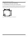
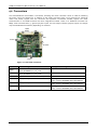
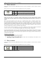
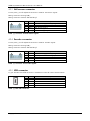
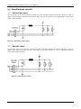
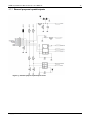
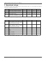
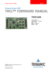
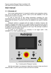
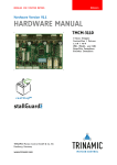
MODULES FOR BLDC MOTORS MODULES V 1.04 HARDWARE MANUAL + + TMCM-1640 1-axis BLDC controller / driver 5A / 24V DC RS485 + USB interface hall sensor interface hallFX™ encoder interface + TRINAMIC Motion Control GmbH & Co. KG Hamburg, Germany www.trinamic.com + TMCM-1640 Hardware Manual (V1.04 / 2011-NOV-16) Table of Contents 1 2 3 4 5 6 7 8 9 Life support policy ....................................................................................................................................................... 3 Features ........................................................................................................................................................................... 4 Order codes .................................................................................................................................................................... 5 Mechanical and electrical interfacing ..................................................................................................................... 6 4.1 Controller/driver board size and mounting holes ..................................................................................... 6 4.2 Connectors ............................................................................................................................................................. 7 4.2.1 Power connector............................................................................................................................................ 8 4.2.2 Motor connector............................................................................................................................................. 8 4.2.3 Hall sensor connector .................................................................................................................................. 9 4.2.4 Encoder connector......................................................................................................................................... 9 4.2.5 USB connector ................................................................................................................................................ 9 4.2.6 GPIOs and RS485 connector ..................................................................................................................... 10 4.3 Input/output circuits ......................................................................................................................................... 11 4.3.1 Hall sensor input ......................................................................................................................................... 11 4.3.2 Encoder input ............................................................................................................................................... 11 4.3.3 General purpose inputs/outputs ............................................................................................................. 12 Operational ratings .................................................................................................................................................... 13 Functional description .............................................................................................................................................. 14 6.1 System architecture ........................................................................................................................................... 14 6.1.1 Microcontroller ............................................................................................................................................. 14 6.1.2 TMC603 3-phase pre-driver ........................................................................................................................ 14 hallFX™ ......................................................................................................................................................................... 15 Revision history .......................................................................................................................................................... 16 8.1 Document revision ............................................................................................................................................ 16 8.2 Hardware revision ............................................................................................................................................. 16 References..................................................................................................................................................................... 16 Copyright © 2011, TRINAMIC Motion Control GmbH & Co. KG 2 TMCM-1640 Hardware Manual (V1.04 / 2011-NOV-16) 1 Life support policy TRINAMIC Motion Control GmbH & Co. KG does not authorize or warrant any of its products for use in life support systems, without the specific written consent of TRINAMIC Motion Control GmbH & Co. KG. Life support systems are equipment intended to support or sustain life, and whose failure to perform, when properly used in accordance with instructions provided, can be reasonably expected to result in personal injury or death. © TRINAMIC Motion Control GmbH & Co. KG 2011 Information given in this data sheet is believed to be accurate and reliable. However neither responsibility is assumed for the consequences of its use nor for any infringement of patents or other rights of third parties, which may result from its use. Specifications are subject to change without notice. Copyright © 2011, TRINAMIC Motion Control GmbH & Co. KG 3 TMCM-1640 Hardware Manual (V1.04 / 2011-NOV-16) 4 2 Features The TMCM-1640 is a highly compact controller/driver module for brushless DC (BLDC) motors with up to 5A coil current, optional encoder and/or hall sensor feedback. For communication the module offers RS485 and (mini-)USB interfaces. Applications Compact single-axis brushless DC motor solutions Electrical data Supply voltage: +24VDC nom. (+12V… +28.5V DC) Motor current: up to 5A RMS (programmable) Integrated motion controller High performance ARM Cortex™-M3 microcontroller for system control and communication protocol handling Integrated driver High performance integrated pre-driver (TMC603) Support for sensorless back EMF commutation (hallFX™) High-efficient operation, low power dissipation (MOSFETs with low RDS(ON)) Dynamic current control Integrated protection Interfaces USB: mini-USB connector, full speed (12Mbit/s) serial communication interface RS485 serial communication interface Hall sensor interface (+5V TTL or open-collector signals) Encoder interface (+5V TTL or open-collector signals) 3 general purpose inputs: 2x digital (+5V / +24V compatible), 1x analogue (0… 10V) 1 general purpose output (open-drain) Software Available with TMCL™ stand-alone operation or remote controlled operation program memory (non volatile) for up to 2048 TMCL™ commands PC-based application development software TMCL-IDE PC-based application development software TMCL-BLDC for initial settings Please refer to separate TMCM-1640 TMCL™ Firmware Manual for further information Copyright © 2011, TRINAMIC Motion Control GmbH & Co. KG TMCM-1640 Hardware Manual (V1.04 / 2011-NOV-16) 5 3 Order codes Cables are not included. Add the TMCM-1640-CABLE to your order if required. Order code TMCM-1640 Component parts TMCM-1640-CABLE Related motors QBL4208-41-04-006 QBL4208-61-04-013 Dimensions [mm] Description 1-axis BLDC controller/driver module with up to 5A / 42 x 42 x 15 28.5V. RS485 and USB 2.0 interface Cable-loom for TMCM-1640 QMot BLDC motor 42 mm, 4000RPM, 0.06Nm QMot BLDC motor 42 mm, 4000RPM, 0.13Nm Table 3.1: Order codes Copyright © 2011, TRINAMIC Motion Control GmbH & Co. KG 42 x 42 x 41 42 x 42 x 61 TMCM-1640 Hardware Manual (V1.04 / 2011-NOV-16) 6 4 Mechanical and electrical interfacing 4.1 Controller/driver board size and mounting holes The dimensions of the controller/driver board (TMCM-164) are approx. 42mm x 42mm in order to fit on the back side of a 42mm NEMA 17 brushless DC motor. Maximum component height (height above PCB level) without mating connectors is around 10mm and about 3mm below PCB level. There are two mounting holes for M3 screws for mounting the board directly to a NEMA 17/42mm flange size brushless DC motor. 39.0 36.5 3 M3 36.5 42.0 39.0 5.5 5.5 3 42.0 Figure 4.1: Module dimension and position of mounting holes Copyright © 2011, TRINAMIC Motion Control GmbH & Co. KG TMCM-1640 Hardware Manual (V1.04 / 2011-NOV-16) 7 4.2 Connectors The controller/driver board offers 6 connectors including the motor connector which is used for attaching the motor coils to the electronics. In addition to the power connector there is one connector for (optional) motor hall sensor signals and one connector for (optional) incremental encoder signals. For serial communication a mini-USB connector has been integrated on-board. There is an additional connector for RS485 serial communication, 3 general purpose inputs and one output. General purpose inputs and output may have dedicated functionality depending on firmware. 1 GPIO RS485 USB 1 Hall Power 1 1 Encoder 1 Motor Figure 4.2: Overview connectors Domain USB Hall Connector type Tyco electronics (formerly AMP) MTA-100 series (3-640456-2), 2 pol., male Tyco electronics (formerly AMP) MTA-100 series (3-640456-3), 3 pol., male 5-pin standard mini-USB connector, female 2mm pitch 5 pin JST B5B-PH-K connector Encoder 2mm pitch 5 pin JST B5B-PH-K connector I/O, RS485 2mm pitch 8 pin JST B8B-PH-K connector Power Motor Mating connector type MTA 100 series (3-640440-2), 2 pol., female MTA 100 series (3-640440-3), 3 pol., female 5-pin standard mini-USB connector, male Housing: JST PHR-5 Crimp contacts: BPH-002T-P0.5S (0.5-0.22mm) Housing: JST PHR-5 Crimp contacts: BPH-002T-P0.5S (0.5-0.22mm) Housing: JST PHR-8 Crimp contacts: BPH-002T-P0.5S (0.5-0.22mm) Copyright © 2011, TRINAMIC Motion Control GmbH & Co. KG TMCM-1640 Hardware Manual (V1.04 / 2011-NOV-16) 8 4.2.1 Power connector A 2-pin Tyco electronics (formerly AMP) MTA-100 series connector (3-640456-2) is used as power connector on-board. Mating connector: Tycos electronics (formerly AMP) MTA-100 series (3-640440-2) 2 1 Pin Label 1 +U 2 GND Description Module + driver stage power supply input Module ground (power supply and signal ground) Table 4.1: Connector for power supply Please note, that there is no protection against reverse polarity and only limited protection against voltages above the upper maximum limit. The power supply typically should be within a range of +9 to +28.5V. When using supply voltages near the upper limit, a regulated power supply is mandatory. Please ensure that enough power filtering capacitors are available in the system (2200µF or more recommended) in order to absorb mechanical energy fed back by the motor in stalling conditions and in order to prevent any voltage surge e.g. during power-on (especially with longer power supply cables as there are only ceramic filter capacitors on-board). In larger systems a zener diode circuitry might be required in order to limit the maximum voltage when the motor is operated at high velocities. The power supply should be designed in a way that it supplies the nominal motor voltage at the desired maximum motor power. In no case shall the supply value exceed the upper voltage limit. To ensure reliable operation of the unit, the power supply has to have a sufficient output capacitor and the supply cables should have a low resistance, so that the chopper operation does not lead to an increased power supply ripple directly at the unit. Power supply ripple due to the chopper operation should be kept at a maximum of a few 100mV. Guidelines for power supply: a) keep power supply cables as short as possible b) use large diameters for power supply cables c) add 2200µF or larger filter capacitors near the motor driver unit especially if the distance to the power supply is large (i.e. more than 2-3m) 4.2.2 Motor connector A 3-pin Tyco electronics (formerly AMP) MTA-100 series connector (3-640456-3) is used as motor connector on-board. Mating connector: Tycos electronics (formerly AMP) MTA-100 series (3-640440-3) 3 1 Pin 1 2 3 Label BM1 BM2 BM3 Description Motor coil phase 1 / U Motor coil phase 2 / V Motor coil phase 3 / W Table 4.2: Connector for brushless DC motor Copyright © 2011, TRINAMIC Motion Control GmbH & Co. KG TMCM-1640 Hardware Manual (V1.04 / 2011-NOV-16) 9 4.2.3 Hall sensor connector A 2mm pitch 5 pin JST B5B-PH-K connector is used for hall sensor signals. Mating connector housing: PHR-5 Mating connector contacts: SPH-002T-P0.5S. 5 1 Pin 1 2 3 4 5 Label GND +5V HALL_1 HALL_2 HALL_3 Description Hall sensor supply and signal ground +5V output for hall sensor supply Hall sensor signal 1 Hall sensor signal 2 Hall sensor signal 3 Table 4.3: Connector for hall sensor signals 4.2.4 Encoder connector A 2mm pitch 5 pin JST B5B-PH-K connector is used for encoder signals. Mating connector housing: PHR-5 Mating connector contacts: SPH-002T-P0.5S. 5 1 Pin 1 2 3 4 5 Label GND +5V A B N Description Hall sensor supply and signal ground +5V output for encoder supply (max. 100mA) Encoder channel a Encoder channel b Encoder index / null channel Table 4.4: Connector for encoder signals 4.2.5 USB connector A 5-pin standard mini-USB connector is available on board for serial communication. 5 1 Pin 1 2 3 4 5 Label VBUS DD+ ID GND Description +5V power Data – Data + Not connected ground Table 4.5: Mini USB connector Copyright © 2011, TRINAMIC Motion Control GmbH & Co. KG TMCM-1640 Hardware Manual (V1.04 / 2011-NOV-16) 10 4.2.6 GPIOs and RS485 connector A 2mm pitch 8 pin JST B8B-PH-K connector is used for connecting general purpose inputs and outputs. Mating connector housing: PHR-8 Mating connector contacts: SPH-002T-P0.5S 1 8 Pin 1 2 Label GND +5V 3 AIN 4 IN_0 5 IN_1 6 7 OUT RS485+ Description Signal and system ground +5V output for supply of external circuit (max. 100mA) Analog input (0… 10V), may be used as velocity control input in standalone mode (depending on firmware) Digital input, may be used as stop (STOP_R) / limit switch input (depending on firmware) Digital input, may be used as stop (STOP_L) / limit switch input (depending on firmware) Digital output (open-drain, max. 100mA) RS485 2-wire serial interface (non-inverted signal) 8 RS485- RS485 2-wire serial interface (inverted signal) Table 4.6: General purpose input/output connector Copyright © 2011, TRINAMIC Motion Control GmbH & Co. KG TMCM-1640 Hardware Manual (V1.04 / 2011-NOV-16) 11 4.3 Input/output circuits 4.3.1 Hall sensor input The hall sensor input circuit supports +5V push-pull (TTL) and open-collector hall sensor signals. In order to support open-collector signals the input circuit offers 2k7 pull-up resistors to +5V (generated on-board from power supply voltage). Figure 4.3: Hall sensor input circuit 4.3.2 Encoder input The encoder input circuit supports +5V push-pull (TTL) and open-collector hall sensor signals. In order to support open-collector signals the input circuit offers 2k7 pull-up resistors to +5V (+5V generated on-board from power supply voltage). Figure 4.4: Encoder input circuit Copyright © 2011, TRINAMIC Motion Control GmbH & Co. KG TMCM-1640 Hardware Manual (V1.04 / 2011-NOV-16) 4.3.3 General purpose inputs/outputs Figure 4.5: General purpose input/output circuit Copyright © 2011, TRINAMIC Motion Control GmbH & Co. KG 12 TMCM-1640 Hardware Manual (V1.04 / 2011-NOV-16) 13 5 Operational ratings The operational ratings shown below should be used as design values. In no case should the maximum values been exceeded during operation. Symbol Parameter Min Typ Max Unit +U Power supply voltage for operation 9 24 28.5 V DC ICOIL Continuous motor current (RMS) 0 3 5 A ISUPPLY Power supply current << ICOIL 1.4 * ICOIL A TENV Environment temperature at rated current (no forced cooling required) tbd °C Table 5.1: General operational ratings of the module Symbol Parameter Min VHALL Signal voltage at hall sensor input 1/2/3 (either push-pull (TTL) or opencollector (internal 2k7 pull-up)) VENCODER Type Max Unit 0 5 V Signal voltage at encoder input a/b/n (either push-pull (TTL) or opencollector (internal 2k7 pull-up)) 0 5 V VAIN Signal voltage at analog input AIN 0 10 V VDIN_1/DIN_2 Signal voltage at digital input DIN_1, DIN_2 0 24 V VDIN_1/DIN_2_L Signal voltage at digital input DIN_1, DIN_2, low level 0 0.8 V VDIN_1/DIN_2_L Signal voltage at digital input DIN_1, DIN_2, high level 2 24 V Table 5.2: Operational ratings of hall sensor, encoder, and general purpose inputs and outputs Copyright © 2011, TRINAMIC Motion Control GmbH & Co. KG TMCM-1640 Hardware Manual (V1.04 / 2011-NOV-16) 14 6 Functional description In Figure 6.1 the main parts of the TMCM-1640 module are shown. The module mainly consists of the Cortex™-M3 CPU, TRINAMICs TMC603A 3-phase pre-driver, the MOSFET driver-stage, and the USB 2.0 interface. EEPROM Hall sensor feedback optional RS485 USB 2.0 Cortex_M3 CPU AIN TMC603 3-phase pre-driver MOSFET driver stage BLDC Motor DIN_1/2 LED_Temp LED_Curlimit 9… +28.5V DC 2 5V 3.3V encoder feedback ABN TMCM-1640 optional Figure 6.1: Main parts of the TMCM-1640 6.1 System architecture The TMCM-1640 integrates a microcontroller with the TMCL™ (Trinamic Motion Control Language) operating system. The motion control real-time tasks are realized by the TMC603A. 6.1.1 Microcontroller On this module, the ARM Cortex™-M3 CPU 32-bit processor is used to run the TMCL™ operating system and to control the TMC603A. The flash ROM of the microcontroller holds the TMCL™ operating system. The EEPROM memory is used to permanently store configuration data. The microcontroller runs the TMCL™ operating system which makes it possible to execute TMCL™ commands that are sent to the module from the host via the interface. The microcontroller interprets the TMCL™ commands and controls the TMC603A which executes the motion commands. The TMCL™ operating system can be updated via the host interface. Please use the latest version of the TMCL-IDE to do this. 6.1.2 TMC603 3-phase pre-driver The TMC603A is a three phase motor driver for highly compact and energy efficient drive solutions. It contains all power and analog circuitry required for a high performance BLDC motor system. The TMC603A is designed to provide the frontend for a microcontroller doing motor commutation and control algorithms. It integrates shunt less current measurement, by using the MOSFETs channel resistance for sensing. Integrated hallFX™ (pat.) allows for sensorless commutation. Protection and diagnostic features as well as a step down switching regulator further reduce system cost and increase reliability. Copyright © 2011, TRINAMIC Motion Control GmbH & Co. KG TMCM-1640 Hardware Manual (V1.04 / 2011-NOV-16) 15 7 hallFX™ hallFX™ provides emulated hall sensor signals. The emulated hall sensor signals are available without a phase shift and there is no error-prone PLL necessary, like with many other systems, nor is the knowledge of special motor parameters required. Since it is based on the motors’ back-EMF, a minimum motor velocity is required to get a valid signal. Therefore, the motor needs to be started without feedback, until the velocity is high enough to generate a reliable hallFX™ signal. Please refer to the TMCM-1640 Firmware Manual for further information about parameterizing the PIDregulator for using hallFX™. Position signal generation (PSG) Switch Cap filters Induction pulse supressor (IPS) U Low pass LPU ULP BM1 E1 D H1 W 30k Low pass LPV VLP BM2 E1 E2 PSG IPS D H2 E2 30k E3 Low pass LPW WLP BM3 V H1 E3 D H3 H2 H3 30k ENRS_TEST D A SP_SUP A FILT3 FILT2 FILT1 SC_CLK A A CSUP Figure 7.1: hallFX™ block diagram and timing A switched capacitor filter for each coil supplies the measured effective coil voltages. Its filter frequency can be adapted to the chopper frequency and the desired maximum motor velocity. An induction pulse suppressor unit gates the commutation spikes which result from the inductive behavior of the motor coils after switching off the current. The gating time can be adapted by an external capacitor to fit the motor inductivity and its (maximum) velocity. Copyright © 2011, TRINAMIC Motion Control GmbH & Co. KG TMCM-1640 Hardware Manual (V1.04 / 2011-NOV-16) 8 Revision history 8.1 Document revision Version Date 0.90 1.00 1.01 1.02 1.03 1.04 2010-MAY-05 2011-FEB-14 2011-MAY-12 2011-OCT-31 2011-NOV-03 2011-NOV-16 Author GE – Göran Eggers SD – Sonja Dwersteg GE SD SD SD SD GE Description Initial version First complete version Minor changes Table for connectors and mating ones new, minor changes Order codes new Table overview mating connectors corrected Table 8.1: Document revision 8.2 Hardware revision Version TMCM-164_V10 TMCM-1640_V10 Date Description 2010-APR-09 First 8 prototype boards 2010-DEC-10 First version pre-series Table 8.2: Hardware revision 9 References [TMCM-1640] [TMCL-IDE and TMCL-BLDC] [TMC603A] [QBL4208] TMCM-1640 TMCL™ Firmware Manual TMCL-IDE User Manual TMC603A Datasheet QBL4208 Manual Please refer to our homepage http://www.trinamic.com. Copyright © 2011, TRINAMIC Motion Control GmbH & Co. KG 16