1
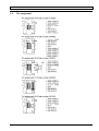
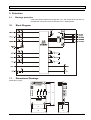
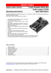
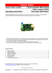
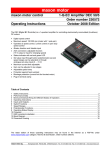
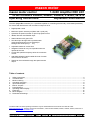
maxon motor
maxon motor control
1-Q-EC Amplifier DEC 24/1
Order numbers 249630, 249631, 249632, 318305, 381510
Operating Instructions
September 2009 edition
The DEC (Digital EC Controller) is a 1-quadrant amplifier for controlling electronically commutated (brushless)
DC motors with Hall sensors with a maximum output of 24 W.
• Digital speed control
• Maximum speed: 120 000 rpm (Motor with 1 pole pair)
• Operation as speed controller or open loop speed control
• /Brake, Direction and /Disable input
• Status indicator with green LED
• Set value input through built-in potentiometer
(several speed ranges can be selected) or
analogue set value input (0 … 5 V)
• Adjustable maximum current limit
• Integrated chokes for very low-impedant motors to
operate at low loss
• Current limit permits temporary twice the continuous
current
• Attachable adapter boards enable all kinds of maxon
micromotors to be used
• Speed can be monitored through the speed monitor
output
Table of contents
1.
2.
3.
4.
5.
6.
7.
8.
9.
10.
11.
Safety Instructions ...........................................................................................................................................2
Technical Data .................................................................................................................................................3
Minimum Wiring ...............................................................................................................................................4
Operating Instruction........................................................................................................................................6
Inputs and Outputs...........................................................................................................................................8
Built-in Jumpers .............................................................................................................................................12
Potentiometers...............................................................................................................................................13
Operating Status Display ...............................................................................................................................14
Protection .......................................................................................................................................................15
Block Diagram................................................................................................................................................15
Dimensional Drawings ...................................................................................................................................15
The latest edition of these operating instructions may be downloaded from the internet as a PDF-file under
www.maxonmotor.com, category «Service & Downloads», order numbers 249630, 249631, 249632, 318305, 381510 or in
the e-shop http://shop.maxonmotor.com.
maxon motor
1-Q-EC Amplifier DEC 24/1
Operating Instructions
1. Safety Instructions
Skilled personnel
Only skilled, experienced personnel should install and start the equipment.
Statutory regulations
The user must ensure that the amplifier and the components belonging to it
are assembled and connected according to local statutory regulations.
Load disconnected
For initial operation, the motor should be free running, i.e. with the load
disconnected.
Additional safety equipment
Any electronic equipment is, in principle, not fail-safe. Machines and apparatus
must therefore be fitted with independent monitoring and safety equipment. If
the equipment breaks down, if it is operated incorrectly, if the control unit
breaks down or if the cables break etc., it must be ensured that the drive or the
complete apparatus is kept in a safe operating mode.
Repairs
Repairs may only be carried out by authorised personnel or the manufacturer.
It is dangerous for the user to open the unit or carry out any repairs.
Danger
Ensure that no apparatus is connected to the electrical supply during
installation of the DEC 24/1! After switching on, do not touch any live parts!
Max. supply voltage
Make sure that the supply voltage is between 5 and 24 VDC. Voltages higher
than 28 VDC or of the wrong polarity will destroy the unit.
Short circuit and earth fault
The amplifier is not protected against winding short circuits against ground
safety earth and/or Gnd!
Electrostatic sensitive device (ESD)
2 maxon motor control
September 2009 edition / document number 555874-04 / subject to change
maxon motor
Operating Instructions
1-Q-EC Amplifier DEC 24/1
2. Technical Data
2.1.
Electrical data
Supply voltage VCC (ripple< 2 %) ................................................................................. 5…24 VDC
Max. output voltage at max output current ....................................................................VCC - 1.5 V
Continuous output current Icont ..................................................................................................1 A
Max. output current Imax.............................................................................................................2 A
Switching frequency of end stage ....................................................................................... 39 kHz
Max. speed (2-pole motor) ......................................................................................... 120 000 rpm
Internal motor chokes per phase.....................................................................150 µH, 1 A, 0.39 Ω
2.2.
Input
Speed .................................................................................................... Analogue input (0 … 5 V)
Resolution: 1024 steps
/Disable ....................................................................................TTL, CMOS (5 V) or switch to Gnd
Direction...................................................................................TTL, CMOS (5 V) or switch to Gnd
/Brake ......................................................................................TTL, CMOS (5 V) or switch to Gnd
Hall Sensor .......................................................................................................................... 1, 2, 3
2.3.
Output
Speed monitor.......................................................................Digital output signal (+5 VDC / 1 kΩ)
2.4.
Voltage output
2.5.
Motor connections
Hall sensors supply voltage “Vcc Hall” .....................................................4.5...5 VDC, max. 30 mA
“Motor winding 1”, “Motor winding 2”, “Motor winding 3”
2.6.
Trim potentiometers
Speed, Imax
2.7.
LED indicator
2.8.
Ambient temperature/humidity range
Operating and fault display: green LED
Operation .................................................................................................................... -10…+45°C
Storage ....................................................................................................................... -40…+85°C
No condensation ............................................................................................................ 20…80 %
2.9.
Protective functions
Blockage protection ....................Motor current limit if minimum speed is not maintained for 1.5 s
2.10.
Mechanical data
Weight........................................................................................................................ approx. 20 g
Dimensions (L x B x H) ...........................................................see dimension drawing, chapter 11
Mounting ............................................................4 hexagonal M3 distance pins with inner winding
Mounting hole separation............................................................................................ 49 x 28 mm
2.11.
Terminals
Power / Signal
Screw terminal ..................................................................................................................... 7-pole
Pitch................................................................................................................................. 2.54 mm
2
suitable for wire cross-section......................................................... 0.14 ... 0.5 mm (AWG 26-20)
Motor and Hall sensors
Flat flexible cable connector, top contact style..................................................................... 8-pole
Pitch................................................................................................................................... 0.5 mm
or
Flat flexible cable connector, top contact style................................................................... 11-pole
Pitch...................................................................................................................................... 1 mm
or
Pin connector with snap-in locking device ........................................................................... 8-pole
Pitch................................................................................................................................... 2.5 mm
or
Screw terminal ..................................................................................................................... 8-pole
Pitch................................................................................................................................. 2.54 mm
2
suitable for wire cross-section......................................................... 0.14 ... 0.5 mm (AWG 26-20)
September 2009 edition / document number 555874-04 / subject to change
maxon motor control 3
maxon motor
1-Q-EC Amplifier DEC 24/1
Operating Instructions
3. Minimum Wiring
3.1.
Operating mode
Power supply
5 – 24 VDC
1
2
3
4
5
6
7
X1
1
3
5
7
9
2
4
6
8
10
X2
JP1
JP2
JP3
LED1
P1 P2
JP3
JP1
JP2
6
P1
X1
set value 0...+5V
6
4 maxon motor control
with external
set value
0 ... 5 V
2
Speed control
X1
set value 0...+5V
with internal
potentiometer
with external
set value
0 ... 5 V
2
Open loop speed control
JP1
JP2
JP3
P1
with internal
potentiometer
Pin assignment X2:
1 Motor winding 1
2 Motor winding 2
3 Motor winding 3
4 VHall 4.5 ... 5 VDC
5 Gnd
6 Hall sensor 1
7 Hall sensor 2
8 Hall sensor 3
9 n.c.
10 n.c.
Pin assignment X1:
1 +VCC 5 – 24 VDC
2 Gnd
3 Direction
4 /Disable
5 /Brake
6 Speed
7 Monitor n
September 2009 edition / document number 555874-04 / subject to change
maxon motor
Operating Instructions
3.2.
1-Q-EC Amplifier DEC 24/1
Pin assignment
September 2009 edition / document number 555874-04 / subject to change
maxon motor control 5
maxon motor
1-Q-EC Amplifier DEC 24/1
Operating Instructions
4. Operating Instruction
4.1.
Power supply layout
Any available power supply can be used as long as it meets the minimum
requirements set out below.
During set-up and adjustment phases, we recommend separating the motor
mechanically from the machine to prevent damage from uncontrolled motion.
Power supply requirements
Output voltage
VCC min. 5 VDC; VCC max. 24 VDC
Ripple
< 2%
Output current
depending on load, continuous max 1 A
acceleration, short-time max. 2 A
The required voltage can be calculated as follows:
Known values
Ö Operating torque MB [mNm]
Ö Operating speed nB [rpm]
Ö Nominal motor voltage UN [V]
Ö Motor no-load speed at UN, n0 [rpm]
Ö Speed/torque gradient of motor ∆n/∆M [rpm/mNm]
Sought values
Ö Supply voltage VCC [V]
Solution
VCC =
UN
∆n
⋅ (n B +
⋅ M B ) + 1.5V
n0
∆M
Choose a power supply capable of supplying this calculated voltage under load.
The formula takes into account a 1.5 V maximum voltage drop (at nominal
current) at the power stage.
Note
Please note chapter 5.1.4, “/Brake” function when using the “/Brake“ input!
6 maxon motor control
September 2009 edition / document number 555874-04 / subject to change
maxon motor
Operating Instructions
1-Q-EC Amplifier DEC 24/1
4.2.
Adjusting the potentiometers
4.2.1.
Pre-adjustment
JP1
JP2
JP3
P1 Speed
With pre-adjustment, the potentiometers are set in a preferred position.
Units in the original packing are already pre-set.
Pre-adjustment of potentiometers
P1
Speed
50 %
P2
Imax
50 %
Note
Left end stop of potentiometers:
Right end stop of potentiometers:
4.2.2.
Minimum value
Maximum value
Adjustment
Digital speed control
Digital open loop speed
control
1.
Depending on operating mode selected, apply set value at the “Speed”
input or with potentiometer P1 so that required speed is reached. If
necessary, adjust maximum speed with built-in jumper JP1 and JP2.
At 0 set value, the speed is NOT 0 rpm. It depends on the pole pair
number of the connected motor (see chapter 6.1).
2.
Adjust potentiometer P2 Imax to required limiting value.
With potentiometer P2, continuous current can be adjusted in a range of
0.1…1 A.
1.
Depending on operating mode selected, apply set value at the “Speed”
input or with potentiometer P1 so that required speed is reached. At 0 set
value, the speed is 0 rpm.
2.
Adjust potentiometer P2 Imax to required limiting value.
With potentiometer P2, the maximum current can be adjusted in a range
of 0.1…1 A.
September 2009 edition / document number 555874-04 / subject to change
maxon motor control 7
maxon motor
1-Q-EC Amplifier DEC 24/1
Operating Instructions
5. Inputs and Outputs
5.1.
Inputs
5.1.1.
Set value “Speed”
The analogue set value is predetermined at the “Speed” input.
The “Speed” input is protected against overvoltage.
Input voltage range
0...+5 V (ref: Gnd)
Input impedance
> 1 MΩ (in range 0...+5 V)
Continuous overvoltage protection
-24...+24 V
Note
If the set value is applied using the “Speed” input, jumper JP3 must not be
plugged in.
5.1.2.
“/Disable”
Enabling or disabling the power stage.
If the “/Disable” connection is not wired up or a voltage set higher than 2.4 V,
the amplifier is activated (Enable).
Release enable
Input open or input voltage > 2.4 V
(motor running)
If the “/Disable” connection is connected to Gnd Potential or at a voltage lower
than 0.8 V, the power stage is high impedant and the motor shaft freewheels
and slows down (Disable).
Block disable
Set input to Gnd or
(power stage switched off)
input voltage < 0.8 V.
The “/Disable” input is protected against overvoltage.
Input voltage range
Input impedance
Continuous overvoltage protection
Delay time
0 ... +5 V
33 kΩ pull-up resistor at +5 V
-24 ... +24 V
approx. 20 ms
Note
If the jumper setting was changed, the new settings are adopted through a
disable-enable procedure.
8 maxon motor control
September 2009 edition / document number 555874-04 / subject to change
maxon motor
Operating Instructions
5.1.3.
1-Q-EC Amplifier DEC 24/1
“Direction”
When the level changes, the motor slows down in an uncontrolled fashion (as
windings are short-circuited, see also chapter 5.1.4, “/Brake” ) and accelerates
in the opposite direction, until the nominal speed is reached again.
The “Direction” input is protected against overvoltage.
Input voltage range
Input impedance
Continuous overvoltage protection
Delay time
0...+5 V
33 kΩ pull-up resistor at +5 V
-24...+24 V
approx. 20 ms
Clockwise (CW)
Input open or input voltage > 2.4 V
Set input to Gnd or
input voltage < 0.8 V.
Counter-clockwise (CCW)
If the direction is changed with a rotating motor shaft, the limitations described
in chapter 5.1.4, “/Brake” must be observed, or the amplifier may be damaged.
5.1.4.
“/Brake” function
If the connection is not wired up or the voltage set higher than 2.4 V, the brake
function is inactive.
Brake function not active
Input open or input voltage > 2.4 V
(motor windings not short-circuited)
If the connection is placed at Gnd potential or the voltage is lower than 0.8 V,
the /brake function is active and the motor shaft slows down to a standstill,
short-circuiting the motor windings. The motor windings remained shortcircuited until the /brake function is deactivated again.
Brake function active
Set input to Gnd or
(motor windings short-circuited)
input voltage < 0.8 V.
The brake function will be executed even if the power stage is disabled.
The “/Brake” input is protected against overvoltage.
Input voltage range
Input impedance
Continuous overvoltage protection
Max. brake current
Delay time
September 2009 edition / document number 555874-04 / subject to change
0...+5 V
33 kΩ pull-up resistor at +5 V
-24...+24 V
10 A
approx. 20 ms
maxon motor control 9
maxon motor
1-Q-EC Amplifier DEC 24/1
Operating Instructions
The maximum permitted brake speed is limited through the maximum permitted
short-circuit current and maximum kinetic energy:
• I <= 10 A
• Wk = 20 Ws
The values can be calculated as follows:
The maximum permitted brake speed can be calculated from the motor data:
max. permitted brake
speed limited by brake
current. (I = 10 A)
nmax = 10 A ⋅ k n ⋅ (RPh − Ph + 1 Ω )
[rpm]
kn = speed constant [rpm/V]
RPh-Ph = terminal resistance phase-phase [Ω]
With the given moment of inertia, the maximum speed can be determined
using the following formula:
max. permitted brake
speed limited by kinetic
energy (Wk = 20 Ws)
nmax =
365
⋅ 10 000 [rpm]
JR + JL
JR = rotor inertia [gcm2]
JL = load inertia [gcm2]
5.1.5.
“Hall sensor 1”, “Hall sensor 2”, “Hall sensor 3”
Hall sensors are needed for detecting rotor position.
“Hall sensor” inputs are protected against overvoltage.
Input voltage range
Input impedance
Voltage value “low”
Voltage value “high”
Continuous overvoltage protection
0...+5 V
10 kΩ pull-up resistor at +5 V
max. 0.8 V
min. 2.4 V
-24...+24 V
Suitable for Hall effect sensors IC using Schmitt trigger and open collector
output.
5.2.
Outputs
5.2.1.
“VCC Hall”
Powering the Hall sensors.
Output voltage
Max. output current
4.5...5 VDC
30 mA
Note
When using long thin lines, the voltage drop can be so great via the lines that
the supply voltage falls below the minimum for Hall sensors.
The maximum cable length for the Hall sensors’ supply voltage between motor
and controller is 10 m. The minimum cross-section is AWG 26.
10 maxon motor control
September 2009 edition / document number 555874-04 / subject to change
maxon motor
Operating Instructions
5.2.2.
1-Q-EC Amplifier DEC 24/1
“Monitor n”
The actual speed of the motor shaft is monitored at the “Monitor n” output of the
electronics. The actual speed is available as a digital signal (high/low) and is
equivalent to a third the commutation frequency.
Output voltage range
Output resistance
0...+5 V
1 kΩ
low level
high level
max. 0.6 V
min. 4.2 V
Sought values: Frequency at “Monitor n” output
f Monitor n =
nist ⋅ z Pol
20
[ Hz ]
nist = speed [rpm]
zPol = Number of pole pairs
Sought values: Motor shaft speed
nist =
f Monitor n ⋅ 20
z Pol
[rpm]
fMonitor n = Frequency at “Monitor n” output [Hz]
zPol = Number of pole pairs
Note
• Interference couplings into the “Monitor n” output (such as through long
lines) should be avoided.
• The “Monitor n” output also functions in disable mode.
September 2009 edition / document number 555874-04 / subject to change
maxon motor control 11
maxon motor
1-Q-EC Amplifier DEC 24/1
Operating Instructions
6. Built-in Jumpers
Operating modes are adjusted using 3 jumpers:
6.1.
Setting mode / speed range
JP1 and JP2 are used to predetermine the operating mode (speed control or open loop speed control)
as well as the speed range.
Motor type
Jumpers
JP1 and JP2
1 pole pair
4 pole pairs
8 pole pairs
Operation as open loop speed control 0...100 %
6.2.
500...120 000 rpm
125...30 000 rpm
63...15 000 rpm
500 ... 40 000 rpm
125 ... 10 000 rpm
63...5 000 rpm
500...10 000 rpm
125...2 500 rpm
63...1 250 rpm
Setting set value input
JP3 is used to select the type of set value input (external set value input or with potentiometer P1).
Jumper JP3
Set value input
Externally with “Speed” value input
Internally with potentiometer P1
Note
If the jumper setting was changed, the new settings are adopted through a disable-enable procedure
(see chapter 5.1.2)
12 maxon motor control
September 2009 edition / document number 555874-04 / subject to change
maxon motor
Operating Instructions
1-Q-EC Amplifier DEC 24/1
7. Potentiometers
7.1.
Potentiometer P1 “Speed”
If jumper JP3 is plugged in, the set speed value is adjusted at potentiometer P1
“Speed”.
Note
Left end stop of potentiometers:
Right end stop of potentiometers:
7.2.
Minimum value (see chapter 6.1)
Maximum value (see chapter 6.1)
Potentiometer P2 “Imax”
Adjusting the continuous current limit in the 0.1…1 A range.
The current adjusted on the potentiometer is available for an unlimited period. In
the short-term (max. 1 s), a higher current is permitted (Imax = 2·Icont), in which
case the time depends on the current pattern’s background. After that time, it is
limited to the continuous current Icont.
Example 1
If the current is at less than 90 % of the continuous current for more than 10 s,
Imax is permitted for another second.
If the motor is loaded for a long time in continuous current operation Icont, a
higher current level is not permitted.
2 Icont
Icont
0.9 Icont
0
1
11
12
Example 2
If the maximum current is required for less than 1 s, the recovery time is
shortened proportionately.
2 Icont
Icont
0.9 Icont
0 0.5
September 2009 edition / document number 555874-04 / subject to change
5.5
6.5
maxon motor control 13
maxon motor
1-Q-EC Amplifier DEC 24/1
Operating Instructions
8. Operating Status Display
The green LED shows the operating status.
Definition
LED on
LED off
8.1.
No green LED
Cause:
• No supply voltage
• Wrong polarity of supply voltage
• Hall sensors’ supply voltage VCC Hall is short-circuited.
8.2.
Green LED constantly lit up
Flashing type (green LED)
LED on
LED off
8.3.
Green LED flashes every second
Flashing type (green LED)
8.4.
Operating status
Amplifier activated, everything OK.
Operating status
Amplifier in “Disable” status.
Green LED flickers or flashes intermittently
The controller recognises invalid conditions in the Hall sensor inputs.
Cause:
• Hall sensors not connected or incorrectly connected
• Intermittent Hall sensor supply lines
• Excessive interference to Hall sensor supply lines
(Solution: change supply line feeds, use shielded cable)
• Faulty Hall sensors in motor
8.5.
Green LED flashes regularly
The following error messages can be distinguished depending on flashing type:
Flashing type (green LED)
Error message
• Motor shaft is blocked
• Load too great
• Imax setting too low
• No winding connection
When switched on, the controller
recognises invalid conditions in the
Hall sensor inputs => check Hall
sensor wiring and Hall sensor
signals.
Note
• If the motor does not turn when in “Enable” mode, the “motor shaft is
blocked” error message will always appear.
• Errors and error displays are temporary and do not have to be confirmed
through Disable/Enable.
14 maxon motor control
September 2009 edition / document number 555874-04 / subject to change
maxon motor
Operating Instructions
1-Q-EC Amplifier DEC 24/1
9. Protection
9.1.
Blockage protection
If the motor shaft is blocked for longer than 1.5 s, the current limit is set at 0.8 A,
provided the current limit was not set lower via Imax potentiometer.
10.
Block Diagram
11.
Dimensional Drawings
57
4
49
Dimension in [mm]
28
4
36
September 2009 edition / document number 555874-04 / subject to change
10
24
maxon motor control 15