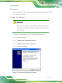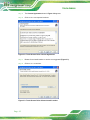
1
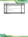
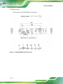
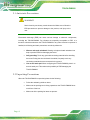
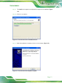
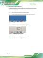
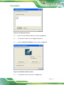
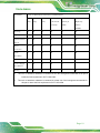
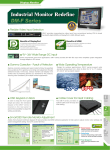
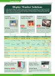
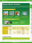
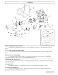
TOUCH-PM6000 TOUCH-PM6000 CPU Card MODEL: TOUCH-P M6000 4, 5, 8-Wire To u c h Co n tro l Bo a rd Us e r Ma n u a l Page 1 Re v. 1.03 - 14 Ma y, 2014 TOUCH-PM6000 Re vis io n Date Version Changes 14 May, 2014 1.03 Update Section 1.2: Model Variations 2 January, 2014 1.02 Update Table 1-6: Operation Systems 5 December, 2013 1.01 Update the pictures for touch control board 16 October, 2013 1.00 Initial release Page 2 TOUCH-PM6000 Co p yrig h t COP YRIGHT NOTICE The information in this document is subject to change without prior notice in order to improve reliability, design and function and does not represent a commitment on the part of the manufacturer. In no event will the manufacturer be liable for direct, indirect, special, incidental, or consequential damages arising out of the use or inability to use the product or documentation, even if advised of the possibility of such damages. This document contains proprietary information protected by copyright. All rights are reserved. No part of this manual may be reproduced by any mechanical, electronic, or other means in any form without prior written permission of the manufacturer. TRADEMARKS All registered trademarks and product names mentioned herein are used for identification purposes only and may be trademarks and/or registered trademarks of their respective owners. Page 3 TOUCH-PM6000 Ta b le o f Co n te n ts 1 INTRODUCTION.......................................................................................................... 1 1.1 INTRODUCTION........................................................................................................... 2 1.2 MODEL VARIATIONS ................................................................................................... 2 1.3 CONNECTOR OVERVIEW ............................................................................................. 3 1.3.1 Touch Panel Connector (RTOUCH1) ................................................................ 3 1.3.2 RS-232/USB Connector (J1) .............................................................................. 3 1.3.3 5 Wire / 4&8 Wire Selection Switch (J_WIRE1) ................................................ 4 1.4 TECHNICAL SPECIFICATIONS ...................................................................................... 4 1.5 DIMENSIONS ............................................................................................................... 6 2 UNPACKING ................................................................................................................. 7 2.1 ANTI-STATIC PRECAUTIONS ........................................................................................ 8 2.2 UNPACKING PRECAUTIONS ......................................................................................... 8 2.3 PACKING LIST............................................................................................................. 9 3 SOFTWARE DRIVERS .............................................................................................. 10 3.1 OVERVIEW.................................................................................................................11 3.2 TOUCH SCREEN DRIVER ............................................................................................11 3.3 CALIBRATING THE TOUCH SCREEN ........................................................................... 14 A HAZARDOUS MATERIALS DISCLOSURE ......................................................... 17 A.1 HAZARDOUS MATERIAL DISCLOSURE TABLE FOR IPB PRODUCTS CERTIFIED AS ROHS COMPLIANT UNDER 2002/95/EC W ITHOUT MERCURY ................................... 18 Page 4 TOUCH-PM6000 Lis t o f Fig u re s Figure 1-1: TOUCH-PM6000 ...........................................................................................................2 Figure 1-2: Connector Overview ...................................................................................................3 Figure 1-3: TOUCH-PM6000 Dimensions (mm) ...........................................................................6 Figure 3-1: Touch Screen Driver Welcome Screen ...................................................................11 Figure 3-2: Touch Screen Driver License Agreement...............................................................12 Figure 3-3: Touch Screen Driver Choose Install Location .......................................................12 Figure 3-4: Touch Screen Driver Installation Screen ................................................................13 Figure 3-5: Touch Screen Driver Update Complete ..................................................................13 Figure 3-6: PenMount Monitor Icon ............................................................................................14 Figure 3-7: PenMount Monitor Popup Menu ..............................................................................14 Figure 3-8: Configuration Screen ................................................................................................15 Figure 3-9: Calibration Initiation Screen ....................................................................................15 Figure 3-10: Calibration Screen ..................................................................................................16 Page 5 TOUCH-PM6000 Lis t o f Ta b le s Table 1-1: Model Variations ...........................................................................................................2 Table 1-2: Touch Panel Connector Pinouts (RTOUCH1) ............................................................3 Table 1-3: RS-232/USB Connector Pinouts (J1) ..........................................................................3 Table 1-4: 5 Wire / 4&8 Wire Selection Switch Pinouts (J_WIRE1) ............................................4 Table 1-5: TOUCH-PM6000 Technical Specifications .................................................................4 Table 1-6: Operation Systems .......................................................................................................5 Page 6 TOUCH-PM6000 Chapter 1 1 In tro d u c tio n Page 1 TOUCH-PM6000 1.1 In tro d u c tio n Figure 1-1: TOUCH-PM6000 The touch panel controller enables analog resistive touch panels for four-wire, five-wire & eight-wire models. The controller directly communicates with the PC system through the touch panel communications interface. The controller design is superior in sensitivity, accuracy, and friendly operation. 1.2 Mo d e l Va ria tio n s The model variations of the resistive touch panels supported by TOUCH-PM6000 are listed below. Models LCD Size Touch Screen Interface T-R065G- R20 6.5” RS-232 T-R065G-USB-R20 6.5” USB T-R084G-R20 8.4” RS-232 T-R084G-USB-R20 8.4” USB T-R104G-R20 10.4” RS-232 T-R104G-USB-R20 10.4” USB T-R121G-R20 12.1” RS-232 T-R121G-USB-R20 12.1” USB T-R150G-R20 15” RS-232 T-R150G-USB-R20 15” USB T-R170G-R20 17” RS-232 T-R170G-USB-R20 17” USB Table 1-1: Model Variations Page 2 TOUCH-PM6000 1.3 Co n n e c to r Ove rvie w The figure below show all the connectors and jumpers. Figure 1-2: Connector Overview 1.3.1 To u c h P a n e l Co n n e c to r (RTOUCH1) PIN NO. DESCRIPTION PIN NO. DESCRIPTION 1 TS_X+ 2 TS_X- 3 TS_Y+ 4 TS_SENSE 5 TS_X+ 6 TS_X- 7 TS_Y+ 8 TS_Y- 9 GND Table 1-2: Touch Panel Connector Pinouts (RTOUCH1) 1.3.2 RS -232/US B Co n n e c to r (J 1) PIN NO. DESCRIPTION PIN NO. DESCRIPTION 1 RS232_DSR 2 RS232_5V 3 RS232_DTR 4 USB_5V 5 RS232_RTS 6 GND 7 RS232_RXD 8 USB_D+ 9 RS232_TXD 10 USB_D- Table 1-3: RS-232/USB Connector Pinouts (J1) Page 3 TOUCH-PM6000 1.3.3 5 Wire / 4&8 Wire S e le c tio n S witc h (J _WIRE1) PIN NO. DESCRIPTION Short A-B 5 Wire Touch Panel Short B-C 4&8 Wire Touch Panel Table 1-4: 5 Wire / 4&8 Wire Selection Switch Pinouts (J_WIRE1) 1.4 Te c h n ic a l Sp e c ific a tio n s TOUCH-PM6000 technical specifications are listed in table below. Model TOUCH-PM6000 Circuit Board Dimension 20mm x 75mm (0.79inches x 2.95inches) Touch 4,5,8-Wire resistance touch Control IC PM6000 OS See Table 1-6 Power Requirements D.C.+5V (100mA typical, 50mV peak to peak) Operating Temperature -25°C to 85°C Storage Temperature -25°C to 85°C Relative Humidity 95% at 60°C, Non-condensing Interface Bi-directional RS-232 serial communication USB:1.1 Full Speed/2.0 Resolution 2048x2048 Table 1-5: TOUCH-PM6000 Technical Specifications The touch panel driver supports the following operating systems: OS Version Interfaces 2000/ XP/ 2003/2008/Vista/7/8 XP-Embedded Windows WinCE 4.1/ 4.2 WinCE 5.0/ 6.0 WEC 7/ 8 Page 4 RS-232/USB TOUCH-PM6000 OS Version Interfaces Fedora (core 5/6/7/8/9/10/11/12/13/14/15/16/17/18/19) SUSE (10.1/10.2/10.3/11/11.1/11.2/11.3/11.4/12.1/12.2/12.3) Debian (4.0 R1/5/6/7) Slackware 12 Linux Ubuntu (6.06/ 6.10/ 7.04/7.1/8.04/8.1/9.04/9.1/10.04/10.1/11.04/ 11.1/ RS-232/USB 12.04/12.1/13.04/13.1) CentOS / RHEL(4.6/5.0-5.8/6.0-6.5) GPM V1.20.6 Tizen 1.0 DOS V2.10 RS-232 Table 1-6: Operation Systems Page 5 TOUCH-PM6000 1.5 Dim e n s io n s The dimensions of TOUCH-PM6000 are listed below: Figure 1-3: TOUCH-PM6000 Dimensions (mm) Page 6 TOUCH-PM6000 Chapter 2 2 Un p a c kin g Page 7 TOUCH-PM6000 2.1 An ti-s ta tic P re c a u tio n s WARNING! Static electricity can destroy certain electronics. Make sure to follow the ESD precautions to prevent damage to the product, and injury to the user. Electrostatic discharge (ESD) can cause serious damage to electronic components, including the TOUCH-PM6000. Dry climates are especially susceptible to ESD. It is therefore critical that whenever the TOUCH-PM6000 or any other electrical component is handled, the following anti-static precautions are strictly adhered to. Wear an anti-static wristband: Wearing a simple anti-static wristband can help to prevent ESD from damaging the board. Self-grounding: Touch any grounded conducting material before handling the board. During the time the board is handled, frequently touch any conducting materials that are connected to the ground. Use an anti-static pad: When configuring the TOUCH-PM6000, place it on an antic-static pad. This reduces the possibility of ESD damaging the TOUCH-PM6000. 2.2 Un pa c kin g P re c a u tio n s When the TOUCH-PM6000 is unpacked, please do the following: Follow the antistatic guidelines above. Make sure the packing box is facing upwards so the TOUCH-PM6000 does not fall out of the box. Page 8 Make sure all the packing list items are present. TOUCH-PM6000 2.3 P a c kin g Lis t NOTE: If any of the components listed in the checklist below are missing, do not proceed with the installation. Contact the IEI reseller or vendor the TOUCH-PM6000 was purchased from or contact an IEI sales representative directly by sending an email to [email protected]. The TOUCH-PM6000 is shipped with the following components: Qu a n tity Ite m 1 TOUCH-PM6000 1 Utility CD Im a g e Page 9 TOUCH-PM6000 Chapter 3 3 S o ftwa re Drive rs P a g e 10 TOUCH-PM6000 3.1 Ove rvie w A CD is shipped with the touch panel controller. The CD contains a user manual and driver for the touch panel controller. 3.2 To u c h S c re e n Drive r WARNING: Before the touch screen driver is installed, make sure the touch panel controller is connected to the resistive touch panel with a USB cable or an RS-232 cable. To install the touch panel software driver, please follow the steps below. S te p 1: Access the driver list. S te p 2: Locate the setup file and double click on it. S te p 3: A Welcome Screen appears (Figure 3-1). S te p 4: Click NEXT to continue. Figure 3-1: Touch Screen Driver Welcome Screen P a g e 11 TOUCH-PM6000 S te p 5: The License Agreement shown in Figure 3-2 appears. S te p 6: Click I AGREE to accept and continue. Figure 3-2: Touch Screen Driver License Agreement S te p 7: Browse for an install location or use the one suggested (Figure 3-3). S te p 8: Click INS TALL to continue. Figure 3-3: Touch Screen Driver Choose Install Location P a g e 12 TOUCH-PM6000 S te p 9: The Install screen appears and displays the progress of the installation (Figure 3-4). S te p 10: Click NEXT to continue. Figure 3-4: Touch Screen Driver Installation Screen S te p 11: When the installation is complete, click F INIS H to exit setup. (Figure 3-5). S te p 0: Figure 3-5: Touch Screen Driver Update Complete P a g e 13 TOUCH-PM6000 3.3 Ca lib ra tin g th e To u c h S c re e n To calibrate the touch screen cursor with the motion of the touch screen pen (or finger), please follow the steps below: S te p 1: Make sure the touch screen driver is properly installed. S te p 2: Locate the PenMount Monitor icon in the bottom right corner of the screen. Figure 3-6: PenMount Monitor Icon S te p 3: Click the icon. A pop up menu appears. See Figure 3-7. Figure 3-7: PenMount Monitor Popup Menu S te p 4: Click Control Panel in the pop up menu shown in Figure 3-7. S te p 5: The configuration screen in Figure 3-8 appears. P a g e 14 TOUCH-PM6000 Figure 3-8: Configuration Screen S te p 6: Double click the PenMount 9000 icon as shown in Figure 3-8. S te p 7: The calibration initiation screen in Figure 3-9 appears. S te p 8: Select the Standard Calibration button as shown in Figure 3-9. Figure 3-9: Calibration Initiation Screen S te p 9: The calibration screen in is shown. See Figure 3-10. P a g e 15 TOUCH-PM6000 Figure 3-10: Calibration Screen S te p 10: Follow the instructions. The user is asked touch the screen at five specified points after which the screen is calibrated. P a g e 16 TOUCH-PM6000 Ap p e n d ix A A Ha za rd o u s Ma te ria ls Dis c lo s u re P a g e 17 TOUCH-PM6000 A.1 Hazardous Material Disclosure Table for IPB Products Certified as RoHS Compliant Under 2002/95/EC Without Mercury The details provided in this appendix are to ensure that the product is compliant with the Peoples Republic of China (China) RoHS standards. The table below acknowledges the presences of small quantities of certain materials in the product, and is applicable to China RoHS only. A label will be placed on each product to indicate the estimated “Environmentally Friendly Use Period” (EFUP). This is an estimate of the number of years that these substances would “not leak out or undergo abrupt change.” This product may contain replaceable sub-assemblies/components which have a shorter EFUP such as batteries and lamps. These components will be separately marked. Please refer to the table on the next page. P a g e 18 TOUCH-PM6000 P a rt Na m e To xic o r Ha za rd o u s S u b s ta n c e s a n d Ele m e n ts Le a d Me rc u ry Ca d m iu m He xa va le n t P o lyb ro m in a te d P o lyb ro m in a te d (P b ) (Hg ) (Cd ) Ch ro m iu m Bip h e n yls Dip h e n yl (CR(VI)) (P BB) Eth e rs (P BDE) Ho u s in g O O O O O O Dis p la y O O O O O O P rin te d Circ u it O O O O O O O O O O O O O O O O O O Fa n As s e m b ly O O O O O O P o we r S u p p ly O O O O O O O O O O O O Bo a rd Me ta l Fa s te n e rs Ca b le As s e m b ly As s e m b lie s Ba tte ry O: This toxic or hazardous substance is contained in all of the homogeneous materials for the part is below the limit requirement in SJ/T11363-2006 X: This toxic or hazardous substance is contained in at least one of the homogeneous materials for this part is above the limit requirement in SJ/T11363-2006 P a g e 19