1
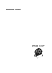
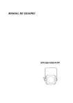
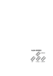
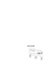
USER MANUAL
PILOT SERIES
BL-10 Pilot
BL-10 R Pilot
BL-10 RO Pilot
BRL-1 Pilot Battery
Pilot Line
Index
1. General description..................................................................................3
Characteristics....................................................................................4
Technical data ....................................................................................5
2. Dimensions ..............................................................................................6
3. Installation................................................................................................8
BL-10 Pilot ..........................................................................................8
BL-10 R Pilot ....................................................................................10
BL-10 RO Pilot..................................................................................11
BRL-1 Pilot Battery ...........................................................................11
BL-2, BL-3, WL-2 and WL-3 Pilot Line and Power Supply 12W
or 50W Pilot Line ..............................................................................12
4. Maintenance ..........................................................................................14
Regular cleaning...............................................................................14
5. Most common problems ........................................................................14
Statement of compliance ............................................................................15
User Manual
POWER 24-3 and 12-3 (TR-M and E-M models)
2
1. General description
Pilot Series is created to satisfy the need of illuminating spaces where
people must displace without having a lot of light.
Use of leds makes this product highly energy-efficient.
PILOT SERIES is composed of the following products:
•
BL-10 Pilot
•
BL-10R Pilot
•
BL-10 RO Pilot
•
BRL-1 Pilot Battery
•
BL-2 Pilot Line and BL-3 Pilot Line
•
WL-2 Pilot Line and WL-3 Pilot Line
All of them incorporate high bright leds. For this reason, they are used as
service lighting in theatres or show rooms.
BRL-1 Pilot Battery, which completes this series, is specially designed for
actors and actresses to displace on the stage without being seen by the
audience.
Power Supply Pilot Line 12W and 50W are also included in this family.
User Manual
POWER 24-3 and 12-3 (TR-M and E-M models)
3
Characteristics
• High bright leds.
• 230V 50Hz single-phase power supply. (BRL-1 Pilot Battery is a oneled portable device that needs to be recharged in a single-phase 230volt 50-hertz power supply. Pilot Line must be supplied with direct
current by means of at least one Power Supply Pilot Line which must be
connected to single-phase 230-volt 50-hertz power supply).
• BL-10, BL-10 R and Power Supply Pilot LIne include holes for PG11
which are drilled on the rear side to hang on a wall. BL-10 RO
incorporates a support to be mounted on a wall. Each Pilot Line can be
mounted thanks to its 2 clamps.
• BRL-1 Pilot Battery let you select led colour between red and blue. It
has a long battery life before having to be recharged. Recharge process
is very quick.
• Pilot Line elements can be connected among them for creating long
linear lighting stretches.
Product references are:
BL-10 Pilot
26000070
BL-10 R Pilot
26000072
BL-10 RO Pilot
26000073
BRL-1 Pilot Battery
26000074
BL-2 Pilot Line // BL-3 Pilot Line
26000092 // 26000093
WL-2 Pilot Line // WL-3 Pilot Line
26000094 // 26000095
Power Supply Pilot Line 12W // 50W
26000098 // 26000099
User Manual
POWER 24-3 and 12-3 (TR-M and E-M models)
4
Technical data
Technical and photometric data of the Pilot Series elements are described
below:
Power supply
Number of leds
Protection
Weight
Single-phase 230V 50Hz
10 blue (BL-10, BL-10 R y BL-10 RO)
2 blue and red (BRL-1 Pilot Battery)
4 blue (BL-2 y BL-3 Pilot Line)
4 white (WL-2 y WL-3 Pilot Line)
PTC resistor
0,3 Kg (BL-10 y BL-10 R)
0,25 Kg. (BL-10 RO)
0,4 Kg. (BRL-1 Pilot Battery)
1,25 Kg. (BL-2 y WL-2 Pilot Line)
1,6 Kg. (BL-3 y WL-3 Pilot Line)
0,45 Kg. (Power Supply 12W Pilot Line)
0,6 Kg. (Power Supply 50W Pilot Line)
Fig. 1: BL-10 Pilot
Fig.2: BL-10 R Pilot
Fig. 3: BL-10 RO Pilot
Fig. 4: Pilot Line
User Manual
POWER 24-3 and 12-3 (TR-M and E-M models)
5
2. Dimensions
Dimensions are in mm.
Fig. 5: BL-10 Pilot
Fig. 6: BL-10 R Pilot
User Manual
POWER 24-3 and 12-3 (TR-M and E-M models)
6
Fig. 7: BL-10 RO Pilot
45
Fig. 8: BRL-1 Pilot Battery
User Manual
POWER 24-3 and 12-3 (TR-M and E-M models)
7
Finally, Pilot Line models (BL-2, BL-3, WL-2 and WL-3) are 2-meter and 3meter lighting, respectively, and their diameter is 30 mm in width. Moreover,
these products require one or more than one power supply, depending on
your needs, which is rectangular in shape and is 280x50x58 mm per unit.
3. Installation
For supplying each unit, you must connect the power supply cable to a
schuko socket of single-phase 230-volt 50-hertz power supply with ground.
Usually, Pilot Series product installation is carried out connecting each unit
to a power supply line (in parallel) for controlling the start and stop of all the
devices together through a switch, which in some cases is integrated into an
ARQ System that belongs to Fresnel S.A. product range (for more information
visit www.strong.es).
BL-10 Pilot
Follow the next steps to connect this product:
1. Unscrew the 4 screws (2 in each side of the unit) which are
indicated in figure 9 and get the front lid off.
Rear frame
Opening for
cables
Front lid
Fig.9
2. Insert the input power supply cables through the opening for
cables which is indicated in figure 9.
User Manual
POWER 24-3 and 12-3 (TR-M and E-M models)
8
3. Connect each power supply cable to its respective input: phase
(F), ground or neutral (N).
Outputs to other
BL-10 (in series)
Power supply
inputs
Fig.10
4. If you want to connect some BL-10 in series, output cables to the
next unit must be connected (see figure 10), if not, outputs can be
left without connections.
5. If some units are connected in series, then, you must insert the
output cables to another BL-10 through the opposite opening for
cables indicated in figure 9 and restart these steps with the other
unit.
6. Eventually, place the front lid on its initial position and screw the 4
bolts which are shown in figure 9.
If you want to mount this unit on a wall, between steps 1 and 2, mark and
drill the 2 holes that are bored in the rear frame and then you will be able to
fasten to the wall. You must be sure that the surface where is mounted can
support it.
User Manual
POWER 24-3 and 12-3 (TR-M and E-M models)
9
BL-10 R Pilot
Follow these steps to install BL-10 R Pilot:
1. Unscrew the 2 bolts that are placed in the upper front lid as shown
in figure 11.
Fig. 11
2. Open this lid until being perpendicular to its support, see figure 12.
Opening for
cables
Fig. 12
3. Insert input power supply cables through the opening indicated in
figure 12.
4. Make cable connections in the terminal strip.
User Manual
POWER 24-3 and 12-3 (TR-M and E-M models)
10
5. In case of connecting some BL-10 R units in series, make the
appropriate connections and insert the output cables through the
opposite opening indicated in figure 12. Then repeat these steps
with the next unit.
6. Screw the bolts indicated in figure 11.
BL-10 RO Pilot
BL-10 RO units are provided with a power supply cable without connector.
For this reason, there are two possibilities: to install a schuko connector for
connecting the unit directly to the wall socket, or to connect the unit to an
installation with a common power supply line.
In both cases, be sure about connecting each cable to each respective
phase, neutral and ground; and do not left any bared wire.
Use the support incorporated, which has two holes, to fasten this device to
the wall. You must be sure that the surface where is mounted can support it.
BRL-1 Pilot Battery
This one-led portable device must be plugged in a 230-volt 50-hertz singlephase wall socket to recharge the internal battery. Once recharged, it can be
used without being connected.
To start with recharge process, you must connect the cable which was
supplied with the unit. One end of the cable must be plugged to the rear side
of the BRL-1 Pilot Battery and the other end must be directly connected to the
wall socket.
User Manual
POWER 24-3 and 12-3 (TR-M and E-M models)
11
When it is connected, a red “on” indicative led, placed in the rear side, is
switched on. When the battery is fully charged, the green “charge finished”
indicative led switch on and you can disconnect the unit. (See figure 13).
Fig. 13
There are 3 different states of working which can be changed by a 3position switch placed in the front side.
Fig. 14
•
Pushing to the left will activate red led.
•
Pushing to the right will activate blue led.
•
In central position the unit will remain stopped.
BL-2, BL-3, WL-2 and WL-3 Pilot Line and Power
Supply 12W or 50W Pilot Line
At least one Power Supply Pilot Line (no matter the version, either 12W or
50W) is necessary to make Pilot Line units work.
Pilot Line lighting bars must be connected to a Power Supply, which is
plugged in 230-volt 50-hertz single-phase wall socket.
User Manual
POWER 24-3 and 12-3 (TR-M and E-M models)
12
Pilot Line units (BL-2, BL-3, WL-2 or WL-3) can be connected among them
for lighting long linear stretches. For calculating the number of power supply
units that are necessary, you can suppose that 1 meter of linear stretch is
equivalent to 1W of necessary power in the Power Supply unit.
Connections between two elements are through square-shape connectors
which are easy to install.
Fig. 15: Female connector
For connecting units in series, you must insert a male connector (power
supply input) into a female connector (power supply output) creating a serial
circuit as shown in figure 16.
to wall socket
Power Supply
Power supply line
...
Pilot Line 1
Pilot Line 2
Pilot Line N
Fig. 16
These connectors can be joined inserting a male one inside a female one.
When you hear a “click”, they will be fitted by the external flange of the male
connector which will have been inserted in the orifice of the female connector.
If you want to fix the Power Supply Pilot Line unit to a wall, mark and drill
the 2 holes that are bored in the rear side, and then screw it on the surface.
BL-2, BL-3, WL-2 and WL-3 Pilot Line incorporate 2 clamps for mounting on a
surface.
User Manual
POWER 24-3 and 12-3 (TR-M and E-M models)
13
4. Maintenance
Regular cleaning
To prevent the growth of dust and dirt which may impair the proper
operation of the equipment, it should be cleaned regularly.
For cleaning it, use a soft, slightly and damp cloth (if the equipment is very
dirty, apply a little liquid detergent to the cloth).
WARNING: Do not use solvents or products containing alcohol. Make sure
that no liquid get inside the equipment.
5. Most common problems
Problem
Usual cause
Solution
Leds do not light
Power supply problem
Check mains connection
One unit does not start up
Wrong connection
Check connections
If the problem persists despite these measures, please contact to
FRESNEL’s Technical Service Department.
Telf 34 93 274 54 28
Telf 34 93 360 02 30
Fax 34 93 274 47 47
If you want to do without this product, do not mix it with the
ordinary waste. There are specific methods and systems
for dividing electronic and electromagnetic used products
that are described in 2002/96/EC directive, which is in
force in the European Community countries.
User Manual
POWER 24-3 and 12-3 (TR-M and E-M models)
14
FRESNEL S.A.
DC-01
STATEMENT OF COMPLIANCE
DATE: 01/01/12
We declare that the products:
Mark:
STRONG
Models:
BL-10 Pilot
BL-10 R Pilot
BL-10 RO Pilot
BRL-1 Pilot Battery
BL-2 Pilot Line y BL-3 Pilot Line
WL-2 Pilot Line y WL-3 Pilot Line
Power Supply Pilot Line 12W / 50W
Year of construction:
2012
Conforms to the following EC directives:
2006/95/EC: In relation to the safety requirements for material
intended for use within specific voltage limits.
2004/108/EC: In relation to the electromagnetic compatibility of
equipment, systems and installations.
Sole administrator
Ángel Torrecillas Redón
Barcelona, January 1st of 2012
Fresnel S.A.
C/ Potosí 40
08030 Barcelona
Spain
Tel: 34 (93) 360 02 30
Fax: 34 (93) 274 47 47
[email protected]
http://www.strong.es
User Manual
POWER 24-3 and 12-3 (TR-M and E-M models)
15