1
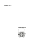
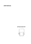
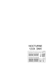
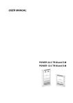
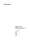
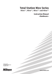
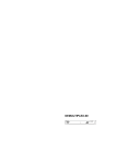
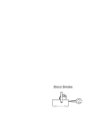
DMX ACCESSORIES
Contents
1.Dimensions
3
2.Connections
4
3.Mixer Description
5-8
4 Splitter Description
9-11
5. Booster Description
12-14
6.Maintenance
15
7.Most Common Problems
16
8.Statement of Compliance
17-19
1.Dimensions
The dimensions are identical for all the items of equipment that comprise the DMX
accessories in the Rack Series: Splitter 1-8, Mixer 2-1 and Booster 4-4.
Figure 1
Likewise, they are the same for all the equipment comprising the DMX accessories
in the Box series: Splitter 1-4, Mixer 2-1 and Booster 2-2.
Figure 2
DMX Accessories
User’s Manual
Ref: 8811042
3
2. Connections
Mains connections are made with
the standard Power Cord supplied
with the equipment, using a cable
with a 1 mm2 section.
The cables used to make the connections on the DMX line should
be low-capacity braided pair and
shielded, with a minimum calibre of
type 24 AWG (0,2047 mm2 )and an
impedance of 120 ohms. It is important to remember that the type
of cable used significantly conditions any problems that may arise
subsequently due to parasites
coming through on the line.
4
Similarly, shielded cables of the type
usually used for connecting microphones should NOT BE USED.
For the connection of the DMX line,
pins 1,2 and 3 at one end of the connector should be connected with their
counterparts on the other end; at the
end of the line a 120 ohm ¼W 1%
resistance between pins 2 and 3. The
screen should be connected to pin 1
and should NOT be in contact with the
casing of the connector. Pins 4 and 5
remain free.
3. Mixer Description
The Mixer 2-1 mixes 2 digital
signals at the input received in
USITT DMX-512 1990 protocol,
converting them into a single digital
output signal.
The way the mixer is adressed
using the rotating switches on the
front panel determines the behaviour of the mixer, that is, the signal
obtained at the ouput.
The address indicated with the
rotating switches will be the first
DMX direction starting from which
the channels from the “IN B” input
will be associated consecutively.
The Mixer has two XLR connectors with
5 male contacts for the digital signal
input and 1 XLR connector with 5 female contacts for the output.
It has a red led indicating that the current is on and three green leds indicating that the DMX signal is being received correctly: input “A”, input “B” and
output “OUT”.
The Box series Mixer 2-1 is identical to
the Rack series mixer, the only difference being the box.
3.1 Characteristics
Mains voltage
Power absorbed
Mains fuse
Digital signal input
Digital signal output
Digital signal input connectors
Digital signal output connector
Casing measurements (Rack series )
Housing window (Rack series)
Net weight (Rack series)
DMX Accessories
220V 50Hz single phase
10 W
5x20 1 A F.F.
USITT DMX-512 1990
USITT DMX-512 1990
XLR 5 male contacts
XLR 5 female contacts
482 x 44mm
450 x 40mm
2,2 Kg
User’s Manual
Ref: 8811042
5
3.2. Connections
23
23
901
901
78
456
901
456
78
78
456
23
Figure 3
1.- ON indicator
2.- DMX signal inputs
3.- Rotating address switches
4.- DMX signal output
6
5.- DMX signal reception indicator
6.- DMX signal output indicator
7.- Safety fuse
8.- Power supply 220V 50Hz
3.3. Example
Let us take an example in which a
DMX line of 48 channels is coming in
through the “IN A” input and another
of 64 channels through the “IN B”
input.
If the direction 49 is selected by the
rotating switches, at the output we
will have a line with 48+64 = 112
channels (lines), the first 48 corresponding to the “IN A” input and
from 49 to 112 the 64 from the “IN B”
input.
DMX Accessories
If the direction selected is 1, the
output will be a line of 64 channels,
where the first 48 will be the highest
value of the 48 channels of the “IN A”
and “IN B” inputs (the highest takes
place) and from 49 to 64 those corresponding to the channels of the
same number from the “IN B” input.
User’s Manual
Ref: 8811042
7
901
23
901
901
78
78
4 56
5
4 6
78
8
4 56
23
Figure 4
23
4. Splitter Description
The Splitter 1-8 (Rack series),
converts the digital signal received
at the input into USITT DMX-512
1990 protocol, into 8 identical digital outputs. That is to say, at the
output 8 copies (replicas) of the
input signal are obtained.
In addition, the Splitter acts as a
signal repeater. An amplified signal
is obtained at each of the outputs.
The Splitter has an XLR connector
with five male contacts for the input
of the digital signal, and 10 XLR
connectors with 5 female contacts
for:
-1 direct output (bridged with the input).
-1 output on the rear casing that is the
same as the one obtained in “OUT 1”
(for the signal output at the rear)
It has one red led indicating that the
current is on and 9 green leds indicating that the DMX signal is being received and emitted correctly (one for
the input and one for each of the eight
outputs).
The Splitter 1-4 Box series differs from
the Rack series version in the number
of amplified outputs (4) and in the fact
that the casing may be suspended from
a structure.
-8 amplified digital signal outputs.
4.1 Characteristics
Mains voltage
Power absorbed
Mains fuse
Digital signal input
Digital signal output
Digital signal input connectors
Digital signal output connector
Casing measurents (Rack series)
Housing window (Rack series)
Net weight (Rack series)
DMX Accessories
220V 50Hz single phase
20 W
5x20 1 A F.F.
USITT DMX-512 1990
USITT DMX-512 1990
XLR 5 male contacts
XLR 5 female contact
482 x 44mm
450 x 40mm
3,5 Kg
User’s Manual
Ref: 8811042
9
4.2. Connections
Figure 5
1.- ON indicator
2.- DMX signal input indicator
3.- DMX signal output indicators
4.- DMX input
5.- Direct DMX signal output
6.- DMX signal outputs
7.- DMX signal output (same as “OUT 1”)
8.- Safety fuse
9.- Power supply 220V 50Hz
4.3. Example
The Splitter needs to be used when
we have an installation that meets
some of these requirements:
1. Large number of loads or pieces of
equipment on one line.
2. Groups of equipment with long
distances between them and the rest
10
(remember that the maximum distance of a DMX signal cable is
500m).
3.-Splitting of the DMX signal, having
a line for each type of load: scanners,
dimmers, effects, etc.
Figure 6
DMX Accessories
User’s Manual
Ref: 8811042
11
5. Booster Description
The Booster 4-4 (Rack series)
obtains 4 amplified DMX signals
from 4 digital signals at the input in
USITT DMX-512 1990 protocol.
That is to say, the Booster acts as
a signal amplifier. For each input
signal an amplified signal is obtained at the output.
The booster has an XLR connector
with 5 male contacts for each of
the digital signal inputs, and an
XLR with 5 female contacts for each of
the digital signal outputs.
It has a red led indicating current, 8
green leds indicating that the DMX
signal is being received (inputs) and
emitted (outputs) correctly.
The Booster 2-2 Box series produces 2
amplified outputs from 2 DMX signal
inputs. It is installed in a box that can
be suspended from a structure.
5.1 Characteristics
Mains voltage
Power absorbed
Mains fuse
Digital signal input
Digital signal output
Digital signal input connectors
Digital signal output connector
Casing measurements (Rack series)
Housing window (Rack series)
Net weight (Rack series)
12
220V 50Hz single phase
20 W
5x20 1 A F.F.
USITT DMX-512 1990
USITT DMX-512 1990
XLR 5 male contacts
XLR 5 female contacts
482 x 44mm
450 x 40mm
3 Kg
5.2. Connections
Figure 7
1.- ON indicator
2.- DMX signal inputs
3.- DMX signal outputs
4.- DMX signal input/output indicator
5.- Safety fuse
6.- Power supply 220V 50Hz
5.3. Example
The Booster is needed when we
have an installation in which the
signal needs to be amplified on account of:
1. Large number of loads or pieces of
equipment on the same line.
or
2.-Cable length (> 500 m).
DMX Accessories
User’s Manual
Ref: 8811042
13
Figure 8
14
6.Maintenance
6.1 Regular Cleaning
To prevent the build-up of dust and
dirt which may impair the proper
operation of the equipment, this
should be cleaned regularly. Use a
soft, slightly damp cloth (if the
equipment is very dirty, apply a little
liquid detergent to the cloth).
WARNING!: Do not use solvents or
products containing alcohol. Make
sure that no liquids get inside the
equipment.
6.2 Changing a Fuse
To change the fuse, switch off the
mains power, with the aid of a screwdriver turn the fuseholder cover anticlockwise until it can be removed.
DMX Accessories
Insert the new fuse and screw the
cover back on.
Important: Use only recommended
fuses
User’s Manual
Ref: 8811042
15
7.The Most Common Problems
Problem
Usual cause
Solution
The ON led does not
light up
No current reaching the
equipment
Check mains connection
Fuse in poor condition
Change fuse
SIG led does not light up Faulty DMX signal
Mixer does not give
output through the required channels
Wrong codification of
rotating switches
Check DMX line installation
Review example 3.3
If the problem persists in spite of these measures, please contact FRESNEL S.A.’s
Technical Service.
Telf: 34 (93)210 7351 / 219 94 60
Fax:34 (93)213 76 61
16
FRESNEL S.A.
DC-01
STATEMENT OF COMPLIANCE
DATE: 1/1/00
We hereby state that the product:
Make:
STRONG
Model:
SPLITTER 1-8/1-4
2001
Year of manufacture:
Complies with directive 73/23 in respect of the safety requirements for electrical material intended for use within specific voltage limits, and with directive
89/336 in respect of the electromagnetic compatibility of equipment, systems
and installations
Sole administrador
Angel Torrecillas Redón
Barcelona, 1 January 2001
Fresnel S.A.
Providencia 109-111
Telf: 34 (93) 2107351 / 2199460
08024 Barcelona
Fax: 34 (93) 2137661
Internet: http:/www.strong.es
E-mail: [email protected]
DMX Accessories
User’s Manual
Ref: 8811042
17
FRESNEL S.A.
DC-01
STATEMENT OF COMPLIANCE
DATE: 1/1/00
We hereby state that the product:
Make:
STRONG
Model:
MIXER 2-1 RACK/BOX
Year of manufacture:
2001
Complies with directive 73/23 in respect of the safety requirements for electrical material intended for use within specific voltage limits, and with directive
89/336 in respect of the electromagnetic compatibility of equipment, systems
and installations.
Sole administrator
Angel Torrecillas Redón
Barcelona, 1 January 2001
Fresnel S.A.
Providencia 109-111
Telf: 34 (93) 2107351 / 2199460
08024 Barcelona
Fax: 34 (93) 2137661
Internet: http:/www.strong.es
E-mail: [email protected]
18
FRESNEL S.A.
DC-01
STATEMENT OF COMPLIANCE
DATE: 1/1/00
We hereby state that the product:
Make:
STRONG
Model:
BOOSTER 4-4/2-2
2001
Year of construction:
Complies with directive 73/23 in respect of the safety requirements for electrical material intended for use within specific voltage limits, and with directive
89/336 in respect of the electromagnetic compatibility of equipment, systems
and installations
Sole administrator
Angel Torrecillas Redón
Barcelona, 1 January 2001
Fresnel S.A.
Providencia 109-111
Telf: 34 (93) 2107351 / 2199460
08024 Barcelona
Fax: 34 (93) 2137661
Internet: http:/www.strong.es
E-mail: [email protected]
DMX Accessories
User’s Manual
Ref: 8811042
19
......