1
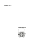
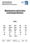
USER MANUAL
POWER 24-3 TR-M and E-M
POWER 12-3 TR-M and E-M
Index
1. General description............................................................................... 3
1.1.Characteristics........................................................................... 4
1.2.Technical data ........................................................................... 5
2. Dimensions ........................................................................................... 6
3. Installation............................................................................................. 7
4. Connection.......................................................................................... 10
4.1.Power supply connection ........................................................ 10
4.2.DMX connection ...................................................................... 11
4.3.PANIC connection ................................................................... 14
4.4.Charge connection .................................................................. 15
5. Programming ...................................................................................... 16
5.1.Configuration ........................................................................... 17
Channel configuration ......................................................... 17
Local mode configuration .................................................... 19
PANIC configuration............................................................ 19
Chaser configuration ........................................................... 20
5.2.Testing ..................................................................................... 20
Frequency test..................................................................... 20
DMX test.............................................................................. 21
Manual test.......................................................................... 21
5.3.System..................................................................................... 22
5.4.Unit information ....................................................................... 22
Channel information ............................................................ 22
System menu ...................................................................... 23
Version menu ...................................................................... 23
6. Maintenance ....................................................................................... 24
6.1.Regular cleaning...................................................................... 24
7. Most common problems ..................................................................... 25
Statement of compliance ......................................................................... 26
User Manual
POWER 24-3 and 12-3 (TR-M and E-M models)
2
1. General description
POWER 24-3 and POWER 12-3 are created to satisfy requirements of
large installations which need high capacity in small space. It is specifically
designed to be mounted on a wall, which reduces the space occupied by them
without using rack boxes.
Output channels can be, in function of your demands, connected through
internal terminals or external ones. The latter consists of a patch situated on
the front side for connecting the installation lines.
They can be controlled by means of DMX-512 digital signal or be
integrated through CAN protocol in an ARQ system (For more information
about architectural system, visit Strong’s website: www.strong.es)
They also include a PANIC function which is a pre-programmed function
which activates in case of emergency.
Each channel is protected by an independent breakdown and optionally
they can be protected in groups of 6 channels without having to install an
external electric panel.
User Manual
POWER 24-3 and 12-3 (TR-M and E-M models)
3
1.1. Characteristics
• DMX-512 digital control or CAN bus (for ARQ system).
• Automatic temperature control by forced ventilation system.
• Independent breaker protection per channel.
• 6-channel circuit breaker protection (optional).
• Protected against overvoltage.
• Automatic mains frequency control.
• LCD display to visualize the dimmer parameters.
• Charge curves that can be applied to each channel: Lineal with voltage,
lineal with light, fluorescent and on/off.
• Test function for checking signal and control power.
• Starting function to increase lamps life span.
• PANIC function.
User Manual
POWER 24-3 and 12-3 (TR-M and E-M models)
4
1.2. Technical data
Common data:
Power supply
400V 50Hz
PANIC connector
Jack stereo
DMX connectors
XLR 5 pins
Guide terminals or external patch
(Wieland 3 poles 16A)
Charge connections
Specific and protection data:
Models
Minimum charge
per channel
Maximum charge
per channel
Total maximum
charge
Rise time filters
24-3 TR-M
User Manual
12-3 E-M
3000 W
72000 W
250µs
36000 W
150µs
250µs
150µs
16 A / channel
6-channel circuit
breaker
Reference
12-3 TR-M
100 W
Output breaker
Weight
24-3 E-M
40A 30mA
48 Kg.
38 Kg.
27 Kg.
20 Kg.
03000063
03000068
03000064
03000069
POWER 24-3 and 12-3 (TR-M and E-M models)
5
2. Dimensions
All the dimmers of this family have the following dimensions:
Fig.1: Dimmer dimensions
User Manual
POWER 24-3 and 12-3 (TR-M and E-M models)
6
3. Installation
To hang the dimmer on a wall, first of all, we must be sure that there is
enough space to mount it. Moreover, dimensions and canalization circuit of
electrical cables must be taken into account.
There must be some distance between the dimmer and other elements
Electrical canalization
around it in order to improve the ventilation of the device.
Fig.2: Distances among devices
First, the upper support must be fixed on the wall considering the height at
which the dimmer is going to be installed, as it is shown in figure 3.
Fig.3: Distance from floor to the support
User Manual
POWER 24-3 and 12-3 (TR-M and E-M models)
7
Then, the dimmer must be hung by the support by the rear side. See figure
4.
Fig.4: Upper dimmer support
Once the dimmer is hung by the support, the door of the dimmer must be
opened for screwing the dimmer to the upper wall support and afterwards the
lower wall support must be hung and bolted to the dimmer (as shown in figure
5).
Fig.5: Lower dimmer support
Next, you must mark the lower support screws on the wall. Eventually, the
lower wall support can be screwed on the wall. See figure 6.
User Manual
POWER 24-3 and 12-3 (TR-M and E-M models)
8
Fig.6: Lower dimmer support
Once mounted, if you want to take down the dimmer, you only will have to
unscrew the two bolts of the upper and lower support which screw the dimmer
to the support (see figure 5).
User Manual
POWER 24-3 and 12-3 (TR-M and E-M models)
9
4. Connection
All the dimmer connections are in the lower side of the dimmer.
Inside the dimmer, there is a connection box for control signal connectors
and in the opposite side there are terminals for connecting the power supply.
DMX in/out connection and
PANIC function
Power supply
Fig.7: Connections
4.1. Power supply connection
The power unit must be connected to a three-phase power supply with
neutral (R, S, T and N) and earth with 400V between phases and 230V
between any phase and neutral.
Power supply terminals must be connected in the right order as shown in
figure 8.
Fig.8: Power supply terminal order
User Manual
POWER 24-3 and 12-3 (TR-M and E-M models)
10
Conductor section has to be chosen following these instructions:
Section* [mm2]
Type of conductor
Power 24-3 TR-M and E-RM
35
Cable
Power 24-3 TR-M and E-RM
16
Cable or multiconnector
Models
*With 400V 50Hz power supply and charges of cosØ=0,8. For more
information about charge consumption and their variations look up the low
tension standards of your country.
These dimmers are protected against wrong connections as it should be to
supply 400V between a phase and neutral. In this case, power unit wouldn’t
start up and it will display the message OVERVOLTAGE during a few seconds
before disappearing. Then, you could proceed to connect the unit in the right
way and turn it on again.
NOTE: It is very important for right working of the power units, to have a
good earth connection. In other case, there could be voltage differences that
would damage the dimmer.
4.2. DMX connection
In the signal connection box (see figure 7) there are input and output DMX
connections.
Fig.9: Signal connection box
The signal connectors are XLR of 5 pins. The signal control from the
control unit must be connected to the DMX IN and the output signal to other
User Manual
POWER 24-3 and 12-3 (TR-M and E-M models)
11
elements in the DMX OUT. You must connect an end-of-line resistance in the
output of the last serial device in order to avoid signal interferences (see figure
10).
The cables should be braided pair, shielded and low capacity, with a type
2
24AWG (0,2047mm ) minimum calibre and an impedance of 120 Ohms.
Please remember that the type of cable significantly conditions any problem
that may arise due to parasites coming through the line.
Similarly, DO NOT USE shielded cables usually used for connecting
microphones.
The cables should be connected in such a way that pin 1 of the male
connector coincides with pin 1 of the female one, and in the same way for pins
2 and 3. Pins 4 and 5 are not used.
The screen connected to pin 1 should NOT come in contact with the casing
of the connector.
CONSOLE
End-of-line
resistance
DMX line
120Ω
...
UNIT 1
UNIT 2
UNIT N
SOLDER SIDE
Fig.10: Signal connection net
The connection should be made exactly as shown in figure 10. You will see
that a resistance of 120 Ohms 1/4W has been installed at the end of the line
between pins 2 and 3. This corresponds to the end-of-line connector supplied
with all projectors.
User Manual
POWER 24-3 and 12-3 (TR-M and E-M models)
12
A maximum of 32 projectors may be linked up to a single line without using
an amplifier. And the maximum cable length as far as the last projector is 1
Km, although it is advisable to use an amplifier for cables every 500 meters.
DMX line
CONSOLE
WRONG
CONNECTION!
UNIT 1
UNIT 3
SOLDER SIDE
UNIT 2
120Ω
...
...
UNIT N
UNIT 4
End-of-line
resistances
UNIT P
Fig.11: Wrong connection
Connection shown in figure 11 is INCORRECT. If an installation divided
into several branches is required, splitters must be used. They distribute and
amplify a single signal into several identical ones in different lines (see Figure
12).
User Manual
POWER 24-3 and 12-3 (TR-M and E-M models)
13
CONSOLE
RIGHT
CONNECTION
DMX line
SPLITTER
UNIT 1
UNIT 3
SOLDER SIDE
120Ω
UNIT 2
UNIT 4
...
...
UNIT N
UNIT P
End-of-line
resistances
Fig.12: Right connection
4.3. PANIC connection
PANIC function connection is carried out through a Jack stereo connector
situated near DMX connectors (see figure 9).
Its connection only requires two cables connected to Jack connector as
shown in figure 13.
Activating switch
for PANIC function
Fig.13: Jack connection (PANIC function)
PANIC function is available by means of a free tension circuit. Thus,
connecting PANIC signal to a switch, function will be activated when pressing
it.
User Manual
POWER 24-3 and 12-3 (TR-M and E-M models)
14
IMPORTANT: Activation of this function has to be by means of a switch,
not with a button.
There is an input and output Jack connector to propagate the signal to
other units.
4.4. Charge connection
Depending on your choice, charge can be connected inside or outside the
power unit.
Externally, connection is by means of Wieland connectors. There are two
outputs per channel which can be connected to different charges. For this fact,
a patch with the dead lines of the installation can be made.
Internally (this connection is more appropriate for small installations where
charge lines are defined beforehand), charges are directly connected inside
the power unit. Subsequently, connections are hidden inside the dimmer.
Fig.14: External and internal charge connectors
User Manual
POWER 24-3 and 12-3 (TR-M and E-M models)
15
5. Programming
The following table shows a map of the dimmer menus and its options. You
can move on the menus pressing “+” and “-” and select an option pressing
“store”.
(Start up)
CONFIG:
CHANNEL:
LOCAL:
LOCAL:
PANIC:
CHASE:
TEST:
FREQ:
DMX:
MANUAL:
SYSTEM:
INFO:
CHANNEL:
SYSTEM:
VERSION:
User Manual
POWER 24-3 and 12-3 (TR-M and E-M models)
16
When the dimmer is starting up, it displays these messages:
5.1. Configuration
To start with the configuration, you must enter to CONFIG menu. You can
move on the menus pressing “+” and “-” and select an option pressing “store”.
Once there, you can select among three options: channels, chasers and
local mode.
Channel configuration
Select CHANNEL to configure the channels.
In this menu, you have two options: channel-per-channel configuration or
all channels together.
XXX: It becomes “ALL” when configuring all the channels together or,
alternatively, shows numbers from 1 to 24 (Power 24-3 models) or from 1 to
12 (Power 12-3 models).
User Manual
POWER 24-3 and 12-3 (TR-M and E-M models)
17
In the former case, parameterization (maximum, minimum, response
curves, etc.) will be equal for all the channels, which starting by the first
channel will increase in one until the end of the total amount of channels of the
dimmer.
When configuring the channels, either together or channel-per-channel,
there will be this message:
YYY: Define the type of response curve.
LIN V – linear with voltage
LIN L - linear with light
FLUO – fluorescent
ON-OFF – Everything or nothing
XX: Address DMX channel to this dimmer channel.
MX: Maximum output value from 0 to F (100%).
MN: Minimum output value
L: Channel value when working in local or PANIC mode.
For validating each option, you must press “store”.
If you configure channel-per-channel, this process must be repeated for
each channel. On the contrary, dimmer channels will be configured with the
same options with the exception of the address.
User Manual
POWER 24-3 and 12-3 (TR-M and E-M models)
18
Local mode configuration
To start this configuration, you must enter to LOCAL menu after selecting
CONFIG.
Then, select LOCAL again.
XXX: You can choose between “ON”, to activate, and “OFF”, to deactivate.
When working in local mode, channel values will be the ones configured
before.
PANIC configuration
The sequence of selections to go to Panic menu is: CONFIG – LOCAL –
PANIC. Then, pressing “ON” is activated.
From now on, if a Panic signal is received through the jack connector
located in the lower internal side of the dimmer (see PANIC connection),
automatically all the channels will be activated with the previously configured
values in the local mode (see Local mode configuration).
User Manual
POWER 24-3 and 12-3 (TR-M and E-M models)
19
Panic signal consists of a free tension contactor which opens or closes a
circuit from an architectural lighting system or any other element which can
carry out the same function (e.g. emergency stop).
Chaser configuration
First of all, you must enter to CHASER menu:
XXX: There are five options: “OFF” (chaser disconnected) or from 1 to 4
(different chasers).
Pressing “+” and “-”, you can select one of the 4 predefined chasers and
then define FADE and TIME times which are from 0 to 8 minutes and 0 to 59
seconds, respectively.
5.2. Testing
This menu is for changing the output level of each channel and verifying
the state of the inputs and outputs: DMX input and mains frequency.
Frequency test
X: It indicates mains frequency value.
User Manual
POWER 24-3 and 12-3 (TR-M and E-M models)
20
Y: It is “OK” if the signal is synchronised with the other phases and “Rf” for
the phase used as reference. If there is no synchronism, it will be “?”.
DMX test
This menu shows the DMX state and any data losing.
When DMX is not detected, it will show this message:
If DMX signal is received:
XX: Number of packs received.
ZZ: Total pack receiving time
Y: If there is any error when receiving the packs.
Manual test
This menu enables you to change manually channel level. The output level
can be selected from 0 to F.
X: Number of channel to modify.
Y: Output level from 0 to F (0-100%).
User Manual
POWER 24-3 and 12-3 (TR-M and E-M models)
21
5.3. System
This menu has three options: unit initialization, unit restoration and
keyboard blockage.
BLOCK: The four buttons are blocked. Press them altogether to unblock it.
INIT: The power unit is initialized with default values.
RESTART: Keeping the programmed parameters of the configuration, the
power unit is reset.
5.4. Unit information
This is a menu which informs about the state of the different parameters of
the dimmer, there are three options: channel information, system menu and
version menu.
Channel information
It shows the state of each channel.
User Manual
POWER 24-3 and 12-3 (TR-M and E-M models)
22
System menu
This is an information menu; consequently, no parameters can be
modified.
If the power unit works in automatic mode (chasers), it will show the times
of FADE and TIME. It will also show local mode state: on or off.
Version menu
It informs about the software version of the dimmer.
User Manual
POWER 24-3 and 12-3 (TR-M and E-M models)
23
6. Maintenance
6.1. Regular cleaning
To prevent the growth of dust and dirt which may impair the proper
operation of the equipment, it should be cleaned regularly.
For cleaning it, use a soft, slightly and damp cloth (if the equipment is very
dirty, apply a little liquid detergent to the cloth).
WARNING: Do not use solvents or products containing alcohol. Make sure
that no liquid get inside the equipment.
User Manual
POWER 24-3 and 12-3 (TR-M and E-M models)
24
7. Most common problems
Problem
Usual cause
Solution
Unit does not start
No current reaching the
unit
Check mains connections
Power unit does not give
response in some channels
Breakers or differentials
activated
Check breakers and differentials
state
Addressing problem
Address channels in free
addresses
See “Programming” section
The unit does not work in
autonomous mode
PANIC function does not
respond
Wrong DMX line
installation
Check the type of cable,
connections, connectors,
installation and 120Ω terminator
resistance
No chaser selected
See “Programming” section
No FADER and TIMER
selected
See “Programming” section
Not activated or not
programming
See “Programming” section
Wrong jack connection
Check connection
See “Connection” section
If the problem persists despite these measures, please contact to
FRESNEL’s Technical Service Department.
Telf 34 93 274 54 28
Telf 34 93 360 02 30
Fax 34 93 274 47 47
If you want to do without this product, do not mix it with the
ordinary waste. There are specific methods and systems
for dividing electronic and electromagnetic used products
that are described in 2002/96/EC directive, which is in
force in the European Community countries.
User Manual
POWER 24-3 and 12-3 (TR-M and E-M models)
25
FRESNEL S.A.
DC-01
STATEMENT OF COMPLIANCE
DATE: 01/01/12
We declare that the products:
Mark:
STRONG
Models:
POWER 24-3 TR-M
POWER 24-3 E-M
POWER12-3 TR-M
POWER 12-3 E-M
Year of construction:
2012
Conforms to the following EC directives:
2006/95/EC: In relation to the safety requirements for material
intended for use within specific voltage limits.
2004/108/EC: In relation to the electromagnetic compatibility of
equipment, systems and installations.
Sole administrator
Ángel Torrecillas Redón
Barcelona, January 1st of 2012
Fresnel S.A.
C/ Potosí 40
08030 Barcelona
Spain
Tel: 34 (93) 360 02 30
Fax: 34 (93) 274 47 47
[email protected]
http://www.strong.es
User Manual
POWER 24-3 and 12-3 (TR-M and E-M models)
26